16575276_ed2 3
4. Lift o the Rear End Plate (102), Cylinder (106) and Vanes (105).
5. Check the Front Rotor Bearing for damage or roughness. If replacement is necessary, support the Front End Plate (107) between two blocks of
wood on the table of an arbor press and press the Rotor from the Front Rotor Bearing.
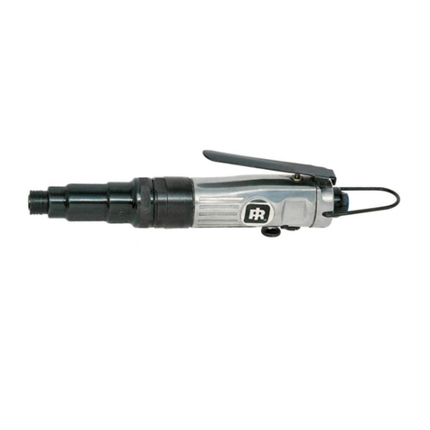
Disassembly of the Lever Throttle Motor Housing
1. Unscrew the Retainer Set Screw (60) from the Reverse Valve (56). Turn the Motor Housing (51) to allow the Lock Pin Retainer (59) to slide from
the hole in the Reverse Valve.
2. Hold the Motor Housing horizontally with the Throttle Lever (54) at the bottom, and withdraw the Reverse Valve 16575276_ed1 EN-2 EN and
Reverse Valve Spring (57), making certain not to drop or lose the Reverse Valve Lock Pin (58).
3. Lightly grasp the ats on the Motor Housing in leathercovered or copper-covered vise jaws so that the Inlet Bushing (73) is upward.
4. Using a small punch or drift, tap the Throttle Lever Pin (55) from the Exhaust Deector (62).
5. Unscrew the Inlet Bushing and remove the Exhaust Deector, Inlet Bushing Spacer (72), Air Strainer Screen (71), Throttle Valve Spring (70) and
Throttle Valve (68). Withdraw the Throttle Valve Plunger (69). If the Plunger Bushing (53A) is to be replaced, withdraw it from the Housing with a
sti wire hook. Slide the Exhaust Silencer (64) and Silencer Seal Ring (65) from the Motor Housing.
6. If the Rear Rotor Bearing (53) is to be replaced, remove the old Bearing by threading a No.10-24 thread cap screw into the Bearing Ejecting Nut
(52) and jacking the Bearing from the Housing (51).
7. If the Throttle Valve Seat (67) and Throttle Valve Seat Support (66) are to be replaced, withdraw them from the Motor Housing with a sti wire
hook.
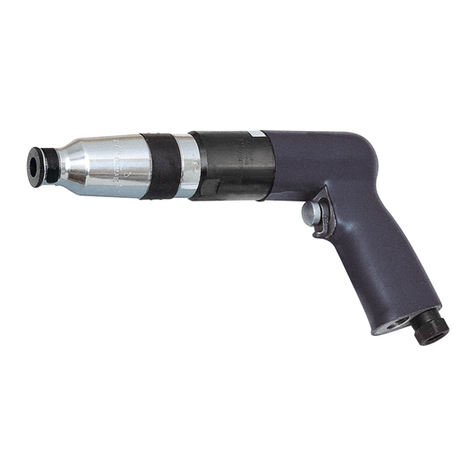
Disassembly of the Pistol Grip Motor Housing
1. Grasp the handle of the Motor Housing (1) in leathercovered or copper-covered vise jaws.
2. If the Rear Rotor Bearing (3) is to be replaced, remove the old Bearing by threading a No. 10-24 thread cap screw into the Bearing Ejecting nut (2)
and jacking the Bearing from the Housing.
3. Unscrew the Reverse Valve Cap (6) and remove the Reverse Valve Spring (5) and Reverse Valve Cap Seal (7).
4. Thread a No. 8-32 thread cap screw into the top of the Reverse Valve (4) and pull the Reverse Valve from the Motor Housing.
A 10mm hexagon socket ts the Actuating Valve Bushing.
5. Unscrew the Actuating Valve Bushing (11) from the Motor Housing, and remove the entire Actuating Valve Assembly, Actuating Valve Spring (15)
and Actuating Valve Bumper (16A).
A 10 mm hexagon socket ts the Actuating Valve Cap.
6. Unscrew the Actuating Valve Cap (14).
7. Unscrew the Inlet Bushing (26) and remove the Inlet Bushing Spacer (25), Air Strainer Screen (27), Muer Assembly (23), Muer (24), Throttle
Valve Spring (22) and Throttle Valve (19).
8. Withdraw the Trigger Assembly (17). If the Trigger Bushing (3A) is to be replaced, withdraw it from the Housing with a sti wire hook.
9. If the Throttle Valve Seat (20) and Throttle Valve Seat Support (21) are to be replaced, withdraw them from the handle with a sti wire hook.
Disassembly of the 7C1 or 7C3 Cushion Clutch
1. Grasp the splined end of the Clutch Driver (205) and pull the entire Clutch Driver Assembly from the Clutch Housing (201).
2. Lightly clamp the splined end of the Clutch Driver in leather-covered or copper-covered vise jaws. Grasp the ats on the Clutch Adjusting Nut
(216) with an adjustable wrench and unscrew the Nut until the compression of the Clutch Spring (211) is relieved.
3. Remove the unit from the vise and while holding it over a small box or container, unscrew the Clutch Adjusting Nut from the Clutch Driver.
Remove the Adjusting Nut Lock (215), Spring Seat Bearing (214), Clutch Spring Seat (213), Clutch Spring Clutch Ball Seat (210) and Clutch
Release Balls (209).
4. If it is necessary to replace the Clutch ball Seat (210), Front Clutch Jaw (206) or Jaw Bearing Balls (207), remove the Spring Seat Stop (212) from
the Groove in the Clutch Driver.
5. Remove the Disengaging Plunger (218) and Disengaging Plunger Spring (217) from the bore of the Clutch Driver.
6. For 7C1 Cushion Clutch, remove the Spring Seat Retainer (221A). Use a ne blade screwdriver and work the rst coil of the Retaining Sleeve
Spring (220) over the end of the Bit holder. Thread the remainder of the Spring over the end of the Bit holder. Be careful not to distort the Spring.
Once the Spring is removed, slide o the Bit Retaining Sleeve (221) and dump the Bit Retaining Ball (222) from the Bit Holder. Tap the large open
end of the Clutch Housing against the top of the workbench to remove the Bit Holder.
7. For 7C3 Cushion Clutch, tap the large open end of the Clutch Housing (201) against the top of the workbench to remove the Bit Holder (223).
Disassembly of the 7D1 Direct Drive Attachment
1. Remove the Spring Sleeve Retainer (307A).
2. Using a ne blade screwdriver, work the rst coil of the Retaining Sleeve Spring (307) over the end of the Bit Holder (305). Thread the remainder
of the Spring over the end of the Bit Holder being certain not to distort the Spring. Once the Spring is removed, slide o the Bit Retaining Sleeve
(308) and dump the Bit Retaining Ball (306) from the Bit Holder. Grasp the splined end of the Bit Holder and pull it from the Housing (301).
Disassembly of the 7P1 or 7P3 Jaw Clutch
1. Remove the Clutch Driver Spacer Retainer (414) from the Clutch Driver (410) and withdraw the Clutch Driver Spacer (411) and rear Clutch
Jaw(408).
2. Remove the Disengaging Plunger (412) and Plunger Spring (413) from the bore of the Bit Holder (404 or 405).
