Ingics iBS03 User manual

INGICS TECHNOLOGY
Guide
Ver.0d
iBS03 User Guide
Introduction
The document is a quick guide for iBS03/iBS03T/iBS03G/iBS03TP/iBS03P/iBS03R. To quickly
verify it, please download INGICS iBS01 Tag Utility APP from below link(Android only):
https://play.google.com/store/apps/details?id=com.ingics.tag.igstagconfig
Power on
One CR2450 battery is pre-installed in each iBS03 beacon at shipment. For transportation safety it is powered off by
default. User should open the case to turn the power on.
Open the case from the gap position,
Because it is airtight, please half open
it from this side then fully open it from
the other side.
Check if the O-ring is still settled at the
correct position during opening.
Switch the small handle to the “ON”
position.
Close the case. To make it airtight,
hold two sides of the case, then twist
back and forth like in the figure below.
For usage in normal
conditions, the
airtight condition will
make iBS03
waterproof.
For harsh environments or tough
conditions, please fix iBS03 by the
attached stainless screws. This will
make iBS03 a more rugged beacon.
Operation
Basically, iBS03 will always transmit BLE payload in the configured time period(default 5s,
iBS03TP 30s) in background. It can be used to track the position of a target by deployment with
iGS01S or iGS02E beacon gateway. Besides background transmission, button or sensor
activation will also trigger a burst of BLE transmission in 300ms(3-4 transmission). This is to
increase the possibility that backends can receive sensor status change.
INGICS TECHNOLOGY CO., LTD. • [email protected] • WWW.INGICS.COM
1

INGICS TECHNOLOGY
Button
As pressing the button the LED will light up and trigger a burst of BLE transmission with a button activation event. As the
back end server received this status change, it can be used as warning or alarming.
Hall Sensor (iBS03)
Inside iBS03, there is a hall sensor that can be used to detect if a magnet is in range or not.
Depending on the strength of the magnet, the range is around 0.5cm~1.5cm. The sensor
position is marked on the enclosure. A typical usage is to put an iBS03 and magnet on the
door(or window) and door frame. When they are close to active range, iBS03 will trigger a series
of BLE transmissions. On the other hand, when they are far away from a close state, it will also
trigger a series of BLE transmissions.
Accelerometer (iBS03G, iBS03RG)
Motion
The accelerometer will be active when it’s status changes. It includes from motion to still or from still to motion.
Fall
There is also a fall detection bit in the payload. When active, it indicates a fall down is detected.
RAW 3-axis
iBS03RG is a special model which will transmit a 3-axis raw accelerometer value in 300ms period. Each transmit will
have
3 records and each record is in a 100ms sampling period.
ToF Sensor (iBS03R)
iBS03R measures ToF distance and transmits measured distance in payload.
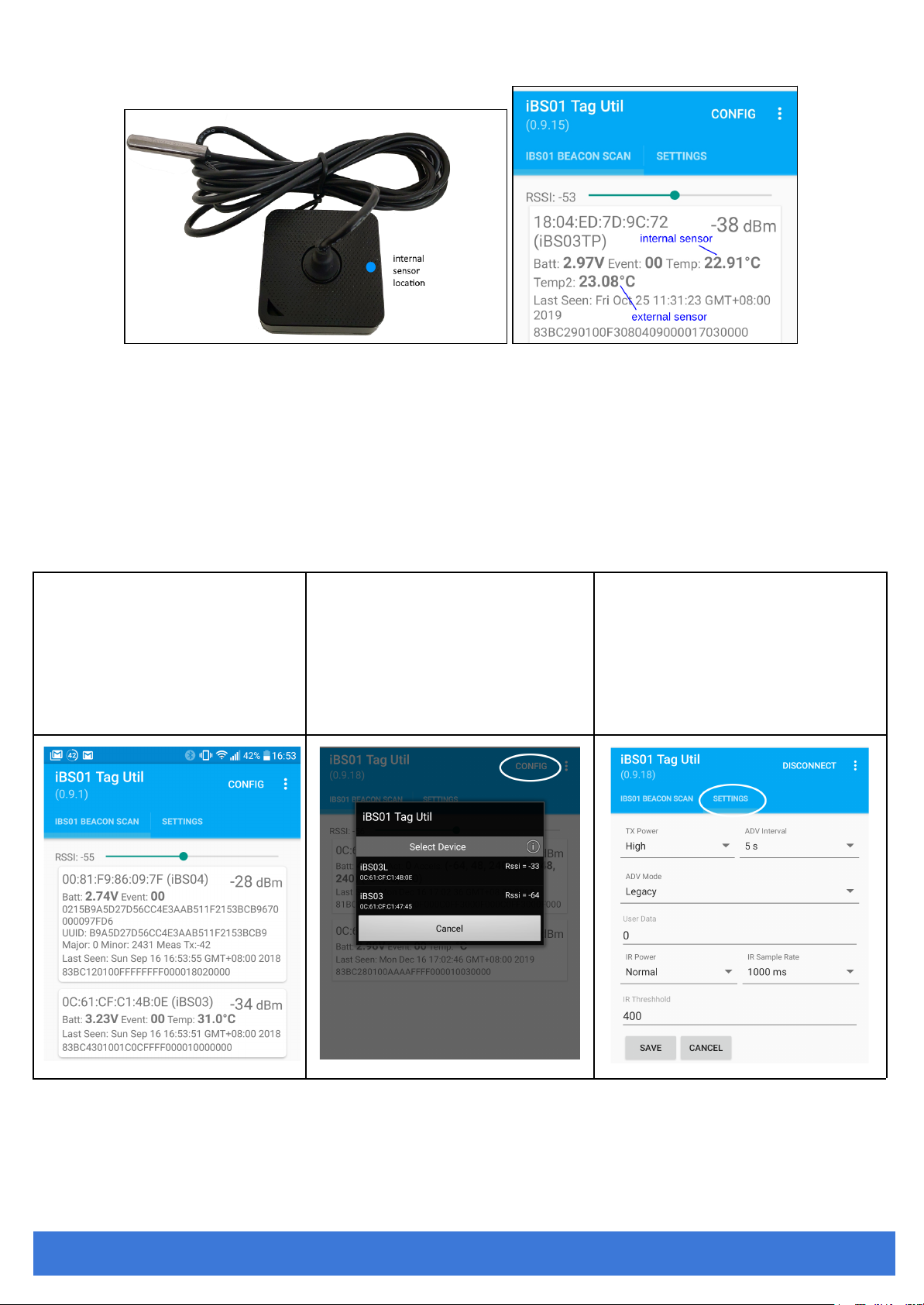
Temperature Sensor (iBS03T, iBS03TP, iBS03P external probe)
iBS03T/iBS03TP/iBS03P will always transmit temperature values in a configured period.
iBS03TP/iBS03P contains internal temperature sensor and external temperature sensor probe as following diagram:
INGICS TECHNOLOGY CO., LTD. • [email protected] • WWW.INGICS.COM
2
INGICS TECHNOLOGY
INGICS iBS01 Tag Utility
When powered on, iBS03 Tag starts to advertise immediately. Users can use iBS01 Tag Utility to scan iBS03 Tag and
configure transmit power and advertising internally of iBS03.
The basic configuration steps is
1. At power on, iBS03 will be in configure mode for 20 seconds.
2. Connect with the utility.
3. Change the parameters and save
4. Disconnect and then the parameter will be effective.
Details is as following
1. Scan iBS03 Beacon
2. Connect iBS03
a. Power on
b. Press CONFIG icon on the up-right
corner of utility within 20 secs
c. You can see iBS03 to be connected
3. Configure iBS03
d. Press iBS03 to connect it.
e. In page SETTING, you will see the
figure below.
f. You can configure the parameters you
want and press SAVE and DISCONNECT
for the parameters to take effect.
INGICS TECHNOLOGY CO., LTD. • [email protected] • WWW.INGICS.COM
3

INGICS TECHNOLOGY
Parameters
In iBS03, there are two parameters that can be configured.
a. TX power: High(+5 dBm), Mid(0 dBm), Low(-6 dBm)
b. ADV Interval: From 100 ms~1 min.
For iBS03R ToF mode can be choosed (default: Short Range mode)
●Short Range Mode: for distance < 1.3 meters measurement, power consumption optimized.
●Long Range Mode: for distance 1.4~3 meters measurement, power consumption as tradeoff.
Waste Electrical and Electronic Equipment Recycling
Our product is compliant with the WEEE directive for re-use/recovery/recycling. This cross-out
wheeled-bin symbol is a reminder that this product should not be treated as household waste. Instead
hand it over to the appropriate collection point for the recycling of electrical and electronic equipment
in accordance with local environmental regulations for waste disposal.
Since our product is not sold directly to the end user and generally it is a part of our customer’s
solution, our customer is recognized as a professional seller. Our customer has the responsibility to
comply with the requirement of the directive too. To help our customers, when necessary, we will
provide a WEEE compliant assessment report for registering and communicating with the local
authorities and recycling agency.
Certification
Japan MIC Regulatory
211-180707
FCC Regulatory
2AH2IIBM40R2
IC Regulatory
21379-IBM40R2
NCC Regulatory
iBS03 CCAJ19LP70E0T0
iBS03G CCAJ19LP70E1T2
iBS03T CCAJ19LP70E2T1
Statement
Federal Communication Commission Interference Statement
This equipment has been tested and found to comply with the limits for a Class B digital device, pursuant to Part 15 of the
FCC Rules. These limits are designed to provide reasonable protection against harmful interference in a residential
installation. This equipment generates, uses and can radiate radio frequency energy and, if not installed and used in
accordance with the instructions, may cause harmful interference to radio communications. However, there is no guarantee
that interference will not occur in a particular installation. If this equipment does cause harmful interference to radio or
television reception, which can be determined by turning the equipment off and on, the user is encouraged to try to correct
the interference by one of the following measures: . Reorient or relocate the receiving antenna. . Increase the separation
between the equipment and receiver. . Connect the equipment into an outlet on a circuit different from that to which the
receiver is connected. . Consult the dealer or an experienced radio/TV technician for help.
FCC Caution:To assure continued compliance, any changes or modifications not expressly approved by the party
responsible for compliance could void the user's authority to operate this equipment. (Example - use only shielded interface
cables when connecting to computer or peripheral devices).
FCC Radiation Exposure Statement This equipment complies with FCC RF radiation exposure limits set forth for an
uncontrolled environment. This equipment should be installed and operated with a minimum distance of 20 centimeters
between the radiator and your body.
This transmitter must not be co-located or operating in conjunction with any other antenna or transmitter. The antennas used
for this transmitter must be installed to provide a separation distance of at least 20 cm from all persons and must not be
co-located or operating in conjunction with any other antenna or transmitter.
This device complies with Part 15 of the FCC Rules. Operation is subject to the following two conditions: (1) This device may
not cause harmful interference, and (2) This device must accept any interference received, including interference that may
INGICS TECHNOLOGY CO., LTD. • [email protected] • WWW.INGICS.COM
4

INGICS TECHNOLOGY
cause undesired operation.
Industry Canada Statement
This device complies with Industry Canada licence-exempt RSS standard. Operation is subject to the following two
conditions: (1) this device may not cause interference, and (2) this device must accept any interference, including
interference that may cause undesired operation of the device.
Le présent appareil est conforme aux CNR d'Industrie Canada applicables aux appareils radio exempts de licence.
L'exploitation est autorisée aux deux conditions suivantes : (1) l'appareil ne doit pas produire de brouillage, et (2) l'utilisateur
de l'appareil doit accepter tout brouillage radioélectrique subi, même si le brouillage est susceptible d'en compromettre le
fonctionnement.
IC Radiation Exposure Statement
This equipment complies with IC RSS-102 radiation exposure limit set forth for an uncontrolled environment. This equipment
should be installed and operated with minimum distance 20cm between the radiator and your body.
Cet équipement est conforme aux CNR-102 d'Industrie Canada. Cet équipement doit êtreinstallé et utilisé avec une distance
minimale de 20 centimètres entre le radiateur et votrecorps. Cet émetteur ne doit pas être co-localisées ou opérant en
conjonction avec autreantenne ou émetteur. Les antennes utilisées pour cet émetteur doivent être installés etfournir une
distance de séparation d'au moins 20 centimètre de toute personne et doit pas être co-située ni fonctionner en conjonction
avec une autre antenne ou émetteur.
NCC 警語
第十二條
經型式認證合格之低功率射頻電機,非經許可,公司、商號或使用者
均不得擅自變更頻率、加大功率或變更原設計之特性及功能。
第十四條
低功率射頻電機之使用不得影響飛航安全及干擾合法通信; 經發現有
干擾現象時,應立即停用,並改善至無干擾時方得繼續使用。
前項合法通信,指依電信法規定作業之無線電通信。
低功率射頻電機須忍受合法通信或工業、 科學及醫療用電波輻射性電
機設備之干擾
INGICS TECHNOLOGY CO., LTD. • [email protected] • WWW.INGICS.COM
5

INGICS TECHNOLOGY
CE Regulatory
iBS03 series(including iBS03/03G/03T, iBS03TP, iBS03R) have been tested and comply with the
essential requirements of the DIRECTIVE 2014/53/EU. Below is the copy of the CE Conformity of
Declaration.
INGICS TECHNOLOGY CO., LTD. • [email protected] • WWW.INGICS.COM
6


INGICS TECHNOLOGY
Revision History
DATE
REVISION
CHANGES
Sep 17, 2018
0a
Initial release
Dec 12, 2019
0b
1. Add regulation statement
2. Add iBS03TP
Jan 22, 2021
0c
Add iBS03P/iBS03R
June 2, 2021
0d
1. Add Waste Electrical and Electronic Equipment Recycling
section for appropriate recycling the equipment
2. Rearrange page and fix typo
3. Add Certification section
INGICS TECHNOLOGY CO., LTD. • [email protected] • WWW.INGICS.COM
9
This manual suits for next models
5
Table of contents
Other Ingics Accessories manuals

Popular Accessories manuals by other brands

Acuity Controls
Acuity Controls Sensor Switch Programming instructions

Baumer
Baumer UNDK 10N8914/S35A manual

Lippert
Lippert Solera 5000 Series Installation and owner's manual

Rice Lake
Rice Lake DINI ARGEO LTP Quick installation guide

Perel
Perel EDKM1 user manual

Thames Side
Thames Side Smart Series OPERATION AND CONFIGURATION MANUAL

adapx
adapx Capturx user guide

PCB Piezotronics
PCB Piezotronics 353B51 Installation and operating manual

Blueant
Blueant Phone Holder manual

Silver Cross
Silver Cross Ride-on Board instruction manual

Aroma-Zone
Aroma-Zone EOLE instruction manual

RADEMACHER
RADEMACHER Superrollo professional SR70030 instruction manual
 Specifications")


