Amphenol 125GMT Series User manual

125GMT10/125GMT15
Installation Guide

2
125GMT
Amphenol Network Solutions
All rights reserved. 3.18.20 150566
509.926.6000 —amphenol-ns.com.com
Installation Guide, Part Number 150566 A0
Copyright 2020, Amphenol Network Solutions, All rights reserved.
Amphenol Network Solutions
22425 E. Appleway Ave #11
Liberty Lake, WA 99019
Amphenol Network Solutions assumes no liability from the application or use of these products.
Amphenol Network Solutions does not convey any license under its patent rights nor the patent
rights of others. This document and the products described herein are subject to change without notice.
About
Amphenol Network Solutions is a global innovative original equipment manufacturer that serves the data
and communications markets. We design, manufacture, and distribute products for customers who need an
end to end solution for network connectivity, fiber, power distribution and rack management. We collaborate
with our customers to deliver product solutions that exceed expectations with innovative designs and world
class quality. Amphenol Network Solutions is the industry thought leader on network cable management.
Telect, Inc. has been a market leader in secondary DC power distribution
for over 36 years. Through our acquisition by Amphenol and our merger
with All Systems Broadband, to become Amphenol Network Solutions, we
have continued to deliver reliable, high-quality solutions to power, protect,
and monitor today’s network servers and equipment. We are proud to be
an Amphenol company that will continue to be Powered by Telect.
Technical Support
Email: support@amphenol-ns.com
Phone: 509.926.6000

3
125GMT
Amphenol Network Solutions
All rights reserved. 3.18.20 150566
509.926.6000 —amphenol-ns.com.com
Table of Contents
Section One: Overview................................................................................................................................ 5
1.1 About this Guide..............................................................................................................................5
1.2 125GMT Configurations................................................................................................................... 6
1.3 125GMT Overview...........................................................................................................................6
1.4 Specifications................................................................................................................................... 8
Section Two: Installation.............................................................................................................................. 9
2.1 Important Installation Guidelines...................................................................................................... 9
2.2 Installation Instructions ....................................................................................................................9
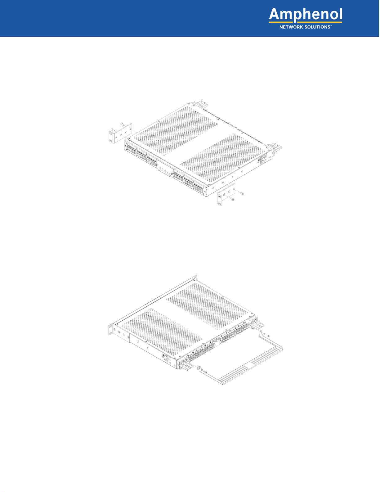
2.2.1 Mounting brackets................................................................................................................ 10
2.2.2 Optional tie bar installation (Connectorized panels only)...................................................... 10
2.2.3 Rack mounting..................................................................................................................... 11
2.2.4 Grounding............................................................................................................................ 12
2.2.5 Input Wiring.......................................................................................................................... 13
2.2.6 Remove alarm cover............................................................................................................ 14
2.2.7 Alarming .............................................................................................................................. 14
2.2.8 Installing fuses..................................................................................................................... 15
2.2.9 Alarm Terminals................................................................................................................... 15
2.2.10 Output wiring (Terminal block versions)............................................................................. 16
2.2.11 Output wiring (Connectorized versions) ............................................................................. 17
2.2.12 Install rear cover ................................................................................................................ 19
2.3 Tie Bar........................................................................................................................................... 20
2.4 Parts & Accessories....................................................................................................................... 20
2.4.1 Ordering Information............................................................................................................ 21
2.4.2 GMT Fuses.......................................................................................................................... 21
2.4.3 Lug Reference Guide........................................................................................................... 22
Section Three: Drawings ........................................................................................................................... 23
3.1 125GMT Drawings......................................................................................................................... 23
List of Figures
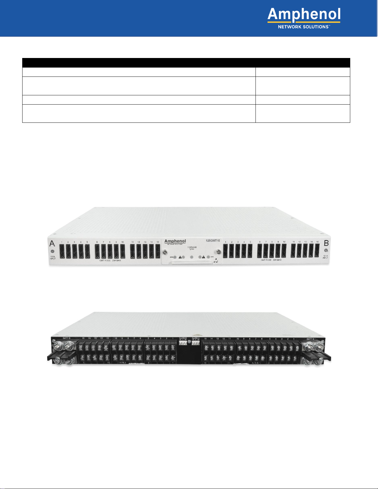
Fig. 1-1: 125GMT15 front view .................................................................................................................... 6
Fig. 1-2: 125GMT15 rear view.....................................................................................................................6
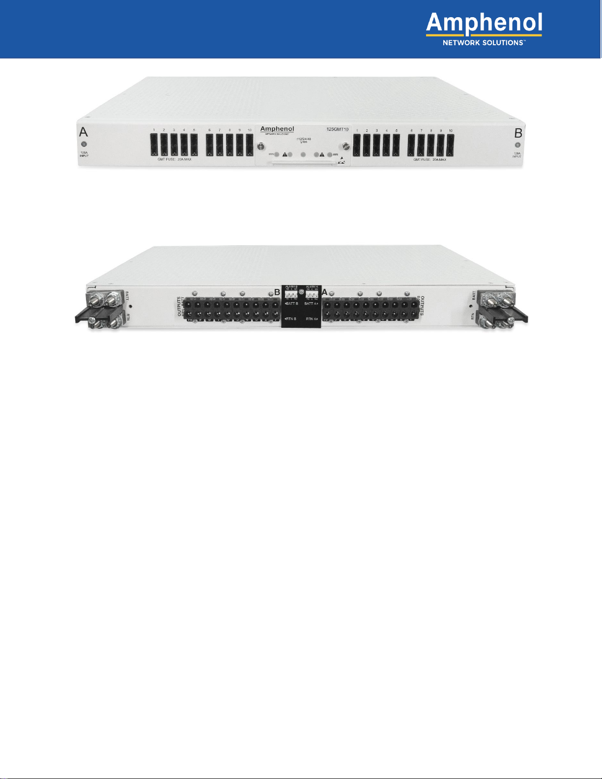
Fig. 1-3: 125GMT10-C front view................................................................................................................. 7
Fig. 1-4: 125GMT10-C rear view .................................................................................................................7
Fig. 2-1: Installing mounting brackets ........................................................................................................ 10

4
125GMT
Amphenol Network Solutions
All rights reserved. 3.18.20 150566
509.926.6000 —amphenol-ns.com.com
Fig. 2-2: Installing optional tie bar.............................................................................................................. 10
Fig. 2-3: Installing panel in rack................................................................................................................. 11
Fig. 2-4: Grounding lug connection............................................................................................................ 12
Fig. 2-5: Input lugs..................................................................................................................................... 13
Fig. 2-6: Removing the alarm cover........................................................................................................... 14
Fig. 2-7: 125GMT15 LED status................................................................................................................ 14
Fig. 2-8: 125GMT15-C Alarm Terminals.................................................................................................... 15
Fig. 2-9: Output lugs.................................................................................................................................. 16
Fig. 2-10: Insert crimped terminals ............................................................................................................ 17
Fig. 2-11: Connector front view.................................................................................................................. 17
Fig. 2-12: Insert retainer ............................................................................................................................ 17
Fig. 2-13: Insert Connector........................................................................................................................ 18
Fig. 2-14: Rear Cover................................................................................................................................ 19
Fig. 2-15: Optional Tie Bar......................................................................................................................... 20
Fig. 3-1: 125GMT10 and 125GMT10-C Front view.................................................................................... 23
Fig. 3-2: 125GMT15 and 125GMT15-C Front view.................................................................................... 23
Fig. 3-3: 125GMT10, 125GMT15, 125GMT10-C and 125GMT15-C Side view.......................................... 23
Fig. 3-4: 125GMT10 Rear view.................................................................................................................. 24
Fig. 3-5: 125GMT15 Rear view.................................................................................................................. 24
Fig. 3-6: 125GMT10-C Rear view.............................................................................................................. 24
Fig. 3-7: 125GMT15-C Rear view.............................................................................................................. 24
Fig. 3-8: 125GMT10 and 125GMT15 Bottom view..................................................................................... 24
Fig. 3-9: 125GMT10-C and 125GMT15-C Bottom view ............................................................................. 24
Fig. 3-10: 125GMT10-C and 125GMT15-C with optional Tie Bar............................................................... 24

5
125GMT
Amphenol Network Solutions
All rights reserved. 3.18.20 150566
509.926.6000 —amphenol-ns.com.com
Section One: Overview
1.1 About this Guide
This manual provides a comprehensive overview of and installation guidelines for the 125GMT family of power
distribution panels. While care has been taken to define all necessary information, complete details may not be
covered. If you have any questions, contact Amphenol Network Solutions Technical Support at
support@amphenol-ns.com or call 1-509-926-6000.
Throughout this guide, select information is highlighted in the form of Notes, Alerts, Cautions, and Warnings.
These notifications are prominent, and their importance is indicated as follows:
NOTE: General information to which the user should pay special attention.
ALERT! Important information and/or instructions to which the user should adhere.
CAUTION! Indicates a hazardous situation, which could result in minor or moderate injury.
WARNING! Indicates a hazardous situation, which could result in death or serious injury.
Amphenol Network Solutions assumes no liability from the application or use of these products. Amphenol
Network Solutions does not convey a license under its patent rights, nor the patent rights of others. This
document and the products described herein are subject to change without notice.

6
125GMT
Amphenol Network Solutions
All rights reserved. 3.18.20 150566
509.926.6000 —amphenol-ns.com.com
1.2 125GMT Configurations
GMT Fuse Panel
Part Number:
125A Dual-Feed, 10/10 Panel, Horizontal Inputs, Output Terminal Blocks
125GMT10
125A Dual-Feed, 10/10 Panel, Horizontal Inputs, Connectorized Outputs
(Connectors purchased separately)
125GMT10-C
125A Dual-Feed, 15/15 Panel, Horizontal Inputs, Output Terminal Blocks
125GMT15
125A Dual-Feed, 15/15 Panel, Horizontal Inputs, Connectorized Outputs
(Connectors purchased separately)
125GMT15-C
1.3 125GMT Overview
The Amphenol Network Solutions 125GMT family of 1RU, dual-feed 125A per feed, power distribution panels
provide high-capacity, ±48V, ±24V, and ±12V power protection for secondary power distribution to data and
communications equipment. The Amphenol Network Solutions 125GMT family panels are also ideal for
primary distribution in small central offices and at remote sites.
Fig. 1-1: 125GMT15 front view
Fig. 1-2: 125GMT15 rear view

7
125GMT
Amphenol Network Solutions
All rights reserved. 3.18.20 150566
509.926.6000 —amphenol-ns.com.com
This panel accommodates Cooper Bussmann and Littelfuse GMT fuses. The 125GMT10 and 125GMT15 have
positions for 20 or 30 GMT fuses, respectively. The panel is UL rated using 20A GMT fuses with a maximum
continuous output load of 14A. GMT fuses are sold separately. See amphenol-ns.com to order GMT fuses.
Sides A and B are electrically isolated including the alarm card, which contains power and GMT fuse status
relays with dry, Form-C contacts. The contacts are connected to wire-wrap pins for connecting to external
visual/audio alarms. Pins can also mate to a TE Connectivity 3-640428-3 connector. The alarm card also
controls the four indicator LEDs on the front panel.
The feed inputs are horizontal and accommodate dual-hole lugs. The input terminals are studs. This panel is
available with standard terminal block outputs or connectorized outputs. All input, output and alarm terminals
are within the panel.
For the terminal block configurations, the outputs are staggered to accommodate waterfall cable management.
Outputs accommodate single-hole lugs and the output terminals are screws.
For the connectorized output configurations, the output cables exit straight back from the panel. The outputs
accommodate connectors that are easily assembled during installation.
The ground terminals can accommodate either dual-hole or single-hole lugs. The ground terminals are bolt
connections on the sides of the panel, near the rear, and on the bottom of the panel, near the center rear. Only
one ground connection is required.
Fig. 1-3: 125GMT10-C front view
Fig. 1-4: 125GMT10-C rear view

8
125GMT
Amphenol Network Solutions
All rights reserved. 3.18.20 150566
509.926.6000 —amphenol-ns.com.com
1.4 Specifications
Inputs:
Specifications:
Voltage range (nominal voltage)
±12VDC, ±24VDC and ±48VDC
Max. input load rating 125GMT10/125GMT15:
125GMT10-C/125GMT15-C:
125A @ 65°C per panel
125A @ 55°C per panel (De-rated to 100A @ 65°C)
Short circuit withstand rating
5000A
Nominal power loss at full load
Less than 45W per side @5,000W full load per side (125A x 48V);
125A @ 65°C per panel
Percentage of full power dissipation at nominal voltage
Less than 0.5%
Max. input interrupt device
125% of panel rating (for 125A rated feeds)
Horizontal input terminal studs (with Keps nuts and flat
washers) for dual-hole compression lugs
Two pairs of ¼-20 studs on 5/8" centers per terminal [max. lug width of .5" (12.7
mm)]. Torque bolts (using 7/16" or 12 mm socket) to 50 in/lb. (5.5 N•m), max.
Input wire size
#8 AWG to #1/0 AWG
Voltage range (nominal voltage)
±12VDC, ±24VDC and ±48VDC
Grounding:
Specifications:
Earth GND terminal bolts (with washers) for dual-hole
compression lug
Three sets of 1/4-20 threaded holes on 5/8" centers. Torque bolts (using 7/16" or 12
mm socket) to 50 in/lb. (5.6 N•m), max.
Ground wire size
#6 AWG to #1 AWG
Outputs:
Specifications:
Output fuse
20A GMT Fuse
Output load
14A continuous
Minimum short circuit interrupt rating
5000A
Optional: Terminal blocks, single-hole compression lugs
20 or 30, #6-32 screws [max. lug width of .31" (7.9)]. Torque screw to 8 in/lb. (.9
N•m), max.
Optional: Output wire size, single-hole compression lug
#22 AWG to #6 AWG
Optional: Connectors (purchased separately)
20 or 30, P24 connector plugs, latching, safe touch
Optional: Output wire size, connectors
#14 AWG to #10 AWG
GMT fuses
Cooper Bussmann and Littelfuse
Alarms:
Specifications:
Alarm relay contacts
2A @ 30VDC; 0.6A @ 60VDC
Max. alarm card power rating
@12V: 18 mA (0.22W); @24V: 20 mA (0.48W); @48V: 30 mA (1.44W)
Alarm wire size
#24 AWG, typical (#26 to #20 AWG)
Alarm terminals
Wire wrap or mates with TE Connectivity 3-640428-3
Dimensions:
Specifications:
125GMT10/125GMT15 Height:
Depth:
Width:
125GMT10-C/125GMT15-C Height:
Depth:
Width:
1.75" (44 mm)
13.9" (353 mm)
17" (432 mm) without brackets
19” and 23” brackets included with panel
1.75" (44 mm)
13.8" (350 mm) without tie bar
16.5" (419 mm) with tie bar
17" (432 mm) without brackets
19” and 23” brackets included with panel
Tie bar not included with panel
Cable-end connectors not included with panel
Compliance:
Specifications:
UL
Listed
NEBS
Level 3

9
125GMT
Amphenol Network Solutions
All rights reserved. 3.18.20 150566
509.926.6000 —amphenol-ns.com.com
Section Two: Installation
2.1 Important Installation Guidelines
•Elevated Operating Ambient Temperature: If installed in a closed or multi-unit rack assembly, the
operating ambient temperature of the rack environment may be greater than room ambient. Consider
installing the equipment in an environment compatible with the maximum ambient temperature (Tma)
specified by the manufacturer.
•Reduced Air Flow: Maintain the amount of air flow required for safe operation when installing the
equipment in a rack.
•Mechanical Loading: Ensure mechanical loading is even to prevent hazardous conditions.
•Circuit Overloading: Overloading circuits may affect your overcurrent protection and supply wiring. Use
equipment nameplate ratings.
•Reliable Earthing: Maintain reliable earthing of rack-mounted equipment. Pay attention to supply
connections other than direct connections to the branch circuit.
•Disconnect Device: Incorporate a readily accessible disconnect device in the building installation wiring.
2.2 Installation Instructions
ALERT! Only qualified technicians may install and maintain this product. Verify all connections meet
requirements specified in local electric codes or operating company guidelines before supplying
power. Protect this equipment with a breaker sufficient to interrupt power levels specified.
ALERT! Verify all connections meet requirements specified in local electric codes or operating
company guidelines before supplying power. Unit shall be protected by a listed circuit breaker or
branch-rated fuse rated minimum 125% of panel rating (for 125A rated feeds).
ALERT! Install this product in locations accessible only to qualified personnel.
Please read these instructions carefully before beginning installation. If assistance is required, call Amphenol
Network Solutions Technical Support at 1-509-926-6000 or email us at support@amphenol-ns.com.
When you receive the equipment, carefully unpack it and compare it to the packaging list. Please report any
defective or missing parts to Amphenol Network Solutions Quality at [email protected]m or call 1-509-
926-6000.
Amphenol Network Solutions is not liable for transit damage. If the product is damaged, please report it to the
carrier and contact Amphenol Network Solutions Quality.
NOTE: For service or warranty information, please visit amphenol-ns.com and click on the support tab, email
Amphenol Network Solutions at getinfo@amphenol-ns.com or call us at 1-509-926-6000.
NOTE: The 125GMT family is suitable for installation as part of a Common Bonding Network (CBN) for
installation in Network Telecommunication Facilities and OSP.
NOTE: The 125GMT family is DC-I and can be grounded in both CBN and IBN networks. All feeds have
isolated returns and the chassis grounds are isolated from all returns. The 125GMT family is suitable for
installation in Network Telecommunication Facilities and in locations where the NEC applies.

10
125GMT
Amphenol Network Solutions
All rights reserved. 3.18.20 150566
509.926.6000 —amphenol-ns.com.com
2.2.1 Mounting brackets
1. The mounting brackets can be installed in 6 positions, from flush to 5 inch offset in 1 inch increments. Use
included hardware to install the mounting brackets. Both 19” and 23” mounting brackets are included.
2. Tighten screws to 20 in/lb. (2.23 N•m).
2.2.2 Optional tie bar installation (Connectorized panels only)
3. Use included hardware in accessory kit to install tie bar. Standard tie bar is available as an accessory for
connectorized panels.
4. Tighten screws to 8 in/lb. (.9 N•m).
Fig. 2-1: Installing mounting brackets
Fig. 2-2: Installing optional tie bar

11
125GMT
Amphenol Network Solutions
All rights reserved. 3.18.20 150566
509.926.6000 —amphenol-ns.com.com
2.2.3 Rack mounting
5. Locate an unused rack position and mount the panel using two sets of fasteners per side, as shown in Fig.
2-3. Mount the panel as high as possible on the rack. Use a seismic rack for best rigidity.
6. Tighten screws to 35 in/lb. (3.9 N•m).
Fig. 2-3: Installing panel in rack

12
125GMT
Amphenol Network Solutions
All rights reserved. 3.18.20 150566
509.926.6000 —amphenol-ns.com.com
2.2.4 Grounding
WARNING! Failure to properly ground this equipment can create hazardous conditions to installation
personnel and to the equipment.
ALERT! Only use components and crimping tools approved by agencies or certifying bodies
recognized in your country or region such as Underwriter’s Laboratories (UL), TUV, etc.
7. Use an approved crimping tool to attach an approved, dual-hole compression lug onto suitable grounding
wire. (Size of ground depends on input interruption device.)
8. If required, lightly coat antioxidant on lug and grounding surface on the side or bottom of the panel.
Connect the lug using 1/4-20 bolts, split washers and flat washers provided, as shown in Fig. 2-4.
9. Tighten the bolt to 50 in/lb. (5.6 N•m), max.
Fig. 2-4: Grounding lug connection

13
125GMT
Amphenol Network Solutions
All rights reserved. 3.18.20 150566
509.926.6000 —amphenol-ns.com.com
2.2.5 Input Wiring
WARNING! Before connecting input power cables, make sure input power to the panel is turned off.
10. Make sure input power is off before connecting the panel’s input cables to the PDU or battery.
11. For input wiring, crimp dual-hole compression lugs onto #8 AWG to 1/0 AWG copper wires. The choice of
input wiring depends on the following criteria:
•Input interrupt device rating affects the size of input wiring.
•Ambient operating temperature affects the type of input wire insulation. For further information,
consult the National Electrical Code (NEC).
12. Insulate the lug barrels with UL94 V-0 rated heat-shrink tubing.
13. Clean terminals and lugs with a non-abrasive, non-metallic pad.
14. If required, lightly coat antioxidant on lugs and input BATT and RTN terminals and then connect lugs to
input terminals, as shown in Fig. 2-5.
15. Tighten nut to 50 in/lb. (5.6 N•m), max.
Fig. 2-5: Input lugs

14
125GMT
Amphenol Network Solutions
All rights reserved. 3.18.20 150566
509.926.6000 —amphenol-ns.com.com
2.2.6 Remove alarm cover
16. Remove alarm cover by using Phillips screwdriver, as shown in Fig. 2-6. Once the front cover has been
taken off the panel, remove and discard the small pink packaging foam piece inside the front cover.
2.2.7 Alarming
17. With all the GMT fuse positions empty, enable the breaker at
the primary distribution unit or battery, 125% of panel rating (for
125A rated feeds) to turn on Feed A to Side A of the panel.
Check voltage and polarity at input connectors of the panel.
Verify the following:
•A PWR LED on the front of panel turns green
•A ALM LED on the front of panel turns red
•B PWR LED remains off
•B ALM LED remains off
18. With A PWR LED green (normal operation) and A ALM LED
red (alarm state) —but with B PWR LED and B ALM LED off
—test ALM relay and contact alarm terminals:
•Expect an open circuit (∞Ω) between terminals C and NC
•Expect continuity (0Ω) between terminals C and NO
19. With no output wires connected or with the output loads (devices fed by this panel) disabled, install fuses
into the fuse positions.
Fig. 2-6: Removing the alarm cover
A PWR
LED
B ALM
LED
A ALM
LED
B PWR
LED
Fig. 2-7: 125GMT15 LED status

15
125GMT
Amphenol Network Solutions
All rights reserved. 3.18.20 150566
509.926.6000 —amphenol-ns.com.com
Verify the following:
•A PWR LED on the front of panel turns green
•A ALM LED turns off
•B PWR LED remains off
•B ALM LED remains off
20. With A PWR LED green (normal operation) and A ALM LED off (normal state) —but with B PWR LED and
B ALM LED off —test A ALM relay and contact terminals:
•Expect continuity (0Ω) between terminals C and NC
•Expect an open circuit (∞Ω) between terminals C and NO
21. Repeat steps 17-20 to power up side B. A PWR and B PWR LEDs must both be green.
NOTE: Dip switches on alarm card are not used and should remain in the off (up) position to prevent false
alarming.
22. Reinstall the cover to the front of the panel using a Phillips screwdriver.
2.2.8 Installing fuses
23. Install GMT fuse into panel in appropriate positions.
24. For any positions without a GMT fuse, a dummy fuse must be inserted in its place. If a fuse is installed
at a later time, remove the dummy fuse and retain for future use.
25. To remove a dummy fuse, use a small pair of needle nose pliers or equivalent to pull it out of position.
2.2.9 Alarm Terminals
26. The alarm terminals are located in the rear center of the panel. Refer to Fig. 2-8.
a. It is possible to use a short, manual wire-wrap tool to install alarm wiring after securing the panel to
the rack. As an alternate to wire wrap, TE Connectivity insulation displacement connector, part
number 3-640428-3, can be used to connect to the alarm terminals.
Fig. 2-8: 125GMT15-C Alarm Terminals
Alarm terminals

16
125GMT
Amphenol Network Solutions
All rights reserved. 3.18.20 150566
509.926.6000 —amphenol-ns.com.com
2.2.10 Output wiring (Terminal block versions)
WARNING! Before connecting output power cables, make sure input power to the panel is turned off.
27. For output wiring, crimp single-hole lugs onto one end of #22 to #10 AWG copper wires, as required by
NEC. (Work with one output wire at a time.)
28. Insulate lug barrels with UL94 V-0 rated heat-shrink tubing.
29. Clean the panel terminal and lugs with a non-abrasive, non-metallic pad.
30. If required, lightly coat antioxidant on lugs and output BATT and RTN terminals and then connect lugs to
terminals, as shown in Fig. 2-9. (NEC specifies only one lug and load at each output terminal.)
ALERT! Do not exceed torque rating. The output terminals are low electrical resistance, free floating
terminals. Note that the top output terminals may rotate slightly within the rear of the panel. This is
normal.
31. Tighten screws to no more than 8 in/lb. (.9 N•m), max. Then connect other end of output wire to load.
32. With the output loads (devices fed by this panel) disabled, re-enable breakers at primary distribution unit or
battery.
33. If applicable, check voltage and polarity at loads.
34. Record circuit assignments in accordance with operating company procedures and guidelines.
35. Enable equipment loads one at a time to verify proper operation of loads.
Fig. 2-9: Output lugs

17
125GMT
Amphenol Network Solutions
All rights reserved. 3.18.20 150566
509.926.6000 —amphenol-ns.com.com
2.2.11 Output wiring (Connectorized versions)
WARNING! Before connecting output power cables, make sure input power to the panel is turned off.
36. Output connectors are available in two sizes, #14-12 AWG and #12-10 AWG. Depending on the output
connector, crimp terminals onto one end of #14 to #10 AWG copper wires using Daniels M300BT crimp
tool or Burndy Y8MRB-1 crimp tool. (Work with one output wire at a time.)
37. Insert terminals into plug housing as shown in Fig. 2-10 and Fig. 2-11. The battery terminal goes in the
position on the connector with 2 locator fins and is marked “2”. The return terminal goes in the position on
the connector with 1 locator fin and is marked “1”.
38. Insert retainer into plug housing as shown in Fig. 2-12.
Fig. 2-10: Insert crimped terminals
Fig. 2-11: Connector front view
Fig. 2-12: Insert retainer
1 Locator Fin: Return
2 Locator Fins: Battery

18
125GMT
Amphenol Network Solutions
All rights reserved. 3.18.20 150566
509.926.6000 —amphenol-ns.com.com
Note: If cables were placed in incorrect position, use a small pair of needle nose pliers or equivalent to
squeeze the retainer latch together. With latches released, grip the plug housing and pull on cables to remove
retainer.
39. Insert the connector into the panel as shown in Fig. 2-13. Ensure that the plug latches into place. Then
connect other end of output wire to load.
40. With the output loads (devices fed by this panel) disabled, re-enable breakers at primary distribution unit or
battery.
41. If applicable, check voltage and polarity at loads.
42. Record circuit assignments in accordance with operating company procedures and guidelines.
43. Enable equipment loads one at a time to verify proper operation of loads.
Fig. 2-13: Insert Connector

19
125GMT
Amphenol Network Solutions
All rights reserved. 3.18.20 150566
509.926.6000 —amphenol-ns.com.com
2.2.12 Install rear cover
WARNING! The rear cover protects the rear of the panel while energized. Not installing the rear cover
may create an electrical hazard.
44. Install rear plastic cover using provided hardware, as shown in fig. 2-14.
Fig. 2-14: Rear Cover

20
125GMT
Amphenol Network Solutions
All rights reserved. 3.18.20 150566
509.926.6000 —amphenol-ns.com.com
2.3 Tie Bar
2.4 Parts & Accessories
The following tables list optional and replacement items for the panel. For wire sizing and labeling, please refer
to Wire Sizing & Label Convention (Amphenol Network Solutions Part No. 117995) included with your panel.
Order parts and accessories online at amphenol-ns.com.
Steps for configuring a panel:
1. Determine the number of load connections required (one load connection per populated fuse position).
2. Select fuses:
•Select fuse quantity equal to the number of load connections
•Select fuse amperage values
Fig. 2-15: Optional Tie Bar
This manual suits for next models
2
Table of contents
Other Amphenol Power Distribution Unit manuals
Popular Power Distribution Unit manuals by other brands

D&R ELECTRONICS
D&R ELECTRONICS PDU14-K Installation & operation manual

Geist
Geist ZP Series instruction manual

Brandywine
Brandywine TDU-310 user guide

Eaton
Eaton Crouse-hinds series Installation & maintenance information

Ametek
Ametek SurgeX Squid SX-DC-8-12-120 user manual

Votronic
Votronic Battery Protector 100 Installation and operating manual