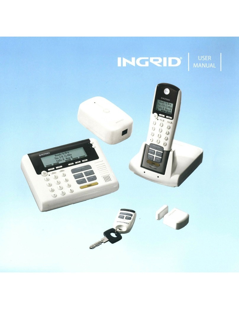
Ingrid Home Security System User manual

USER
MANUAL
© 2008 InGrid, Inc. All rights reserved. InGrid logo is a registered trademark and InGrid Home Securit is a trademark of InGrid Services, LLC.

Getting Sta ted
G E T T I N G S T A R T E D [www.InG idHome.com]
[i]
Use Quick Setup Guide for installation instructions. Sa e both Quick Setup Guide and User Manual for future reference.
Using This Manual
The manual is divided into 4 main sections or easy use. These sections are:
• Introduction
• Using Your Security System
• Using Your Telephone System
• Supplemental In ormation
Throughout the manual the ollowing icons will be used to bring attention to in ormation you may ind help ul.
Security System
Until you have activated your service the InGrid Home Security plat orm will have limited unctionality. You will be able to install the system and use the 2.4GHz
cordless phone eatures. See Phone System section below. No security unctions will be active. Complete the installation, then activate system at
www.myingrid.com.
Central monitoring services will be available or subscribers o pro essional monitoring services once emergency in ormation has been obtained and veri ied, and
the 7-day practice time has expired.
Phone System
Features and backup alarm communication related to your phone are only available or those subscribers that have the appropriate phone services rom their
service provider o choice. Backup communication o alarms may not be available i broadband is down, or i your system phone service uses VoIP or digital voice.
Check with your phone or broadband service provider.
Minimum System Requirements
• Broadband service
• Broadband router with available Internet (Ethernet) port
• MAC or PC with access to Internet
• Phone service (I not available, phone operation and backup communication will be limited or nonexistent.)
t
i!
Info mation Tips Ale ts
Icon Key Codes Cha t

Important Safety Instructions
IM ORTANT SAFETY INSTRUCTIONS
[www.InGridHome.com] [ii]
When using this system, basic safety precautions should always be followed to reduce the risk of fire, electric shock or personal injury.
1. Read and understand Quick Setup Guide and User Manual instructions.
2. Follow all warnings and instructions marked on the individual components provided in the system.
3. Unplug individual components from AC outlets before cleaning. Do not use liquid or aerosol cleaners. Use a damp cloth for cleaning.
4. Do not use individual components near water (such as sinks, bathtubs or swimming pools).
5. Place individual components securely on stable surface.
6. Do not cover slots and openings on any of the individual system components. They are provided for ventillation, to reduce over heating and audio sirens, to
alert you of an alarm.
7. Use only power source marked on system components. If you are not sure of the type of power supplied to your home, consult your local power company.
8. Do not place objects on the power cord. Install the system components where no one can trip on the cords.
9. Do not overload wall outlets and extension cord. This can result in the risk of fire or electric shock.
10. Never push any objects through slots in system components. This may result in the risk of fire or electric shock. Never spill any liquid on any of the
system components.
11. To reduce risk of electric shock, do not disassemble any components provided in the system. If you are having a problem, please call
InGrid Customer Support.
12. Unplug the system components from the wall outlet and call Customer Support when the following conditions occur:
A. When power supply cord or plug is damaged or frayed.
. If liquid has been spilled on a component.
C. If a component has been exposed to rain or water.
D. If a component has been dropped or physically damaged.
E. If a component exibits a distinct change in performance.
13. During thunderstorms, avoid using telephone except cordless types. Use a surge protector to protect equipment.
14. Do not use these components to report a gas leak, when in the vicinity of the leak.
Battery Safety Instructions:
To reduce the risk of fire or injury, read and follow these instructions.
1. Use only the battery(ies) specified. There is a risk of explosion if you replace the battery(ies) with the incorrect battery type.
2. Rechargeable batteries must be disposed of properly and may need to be recycled. Check with local waste mangement codes for special disposal instructions.
3. Do not burn, disassemble, mutilate or puncture the battery(ies). The battey(ies) contain toxic material that could be released, resulting in injury.
4. Exercise care in handling batteries in order not to short the battery to conductive material.
5. Charge the batter(ies) provided with, or identified for use with, the system components only in accordance with the instructions and limitations specified in
this manual.

List of Contents
L I S T O F C O N T E N T S [www.InGridHome.com]
[iii]
InGrid Home Security Introduction.......................................................................................................................................................1
Overview .............................................................................................................................................................................................1
Features...............................................................................................................................................................................................2
Displays and Menus ...........................................................................................................................................................................3
My InGrid.com.....................................................................................................................................................................................5
Central Monitoring .............................................................................................................................................................................7
Using Your Security System ...................................................................................................................................................................9
Base Controls and Functions ...........................................................................................................................................................10
Console Controls and Functions......................................................................................................................................................11
Grid Extender Controls and Functions ...........................................................................................................................................12
Handset Controls and Functions.....................................................................................................................................................13
Keychain Controls and Functions....................................................................................................................................................14
Sensor Controls and Functions........................................................................................................................................................15
Arm Modes ........................................................................................................................................................................................16
Arming/Disarming Your System ......................................................................................................................................................17
Bypassing Sensors ............................................................................................................................................................................19
Exit Delays.........................................................................................................................................................................................20
Entry Delays ......................................................................................................................................................................................21
Exit and Entry Delay Tones/Alarms................................................................................................................................................22
anic Alarms .....................................................................................................................................................................................23
Chime.................................................................................................................................................................................................25
User Codes ........................................................................................................................................................................................26
Suppressing Trouble Sounds ...........................................................................................................................................................29
Event Log/Network Configuration..................................................................................................................................................30
Home Connect...................................................................................................................................................................................31
Notifications ......................................................................................................................................................................................33
Home Alerts/Weather Updates .......................................................................................................................................................36

List of Contents
L I S T O F C O N T E N T S
[www.InGridHome.com] [iv]
Using Your Telephone System..............................................................................................................................................................37
Controls and Functions ....................................................................................................................................................................38
Telephone Operations ......................................................................................................................................................................40
hone Book Operations ....................................................................................................................................................................46
Answering System Operation..........................................................................................................................................................49
rivacy/Do Not Disturb (DND) .........................................................................................................................................................55
Setting Up an Intercom Session.......................................................................................................................................................56
Setting Up Room Monitoring ...........................................................................................................................................................57
Enable Remote Access/Use Remote Access ..................................................................................................................................58
Supplemental Information....................................................................................................................................................................59
Expand Your System.........................................................................................................................................................................59
Glossary .............................................................................................................................................................................................60
General Troubleshooting..................................................................................................................................................................63
System Messages .............................................................................................................................................................................70
recautions & Warnings/Warranty .................................................................................................................................................73
Contact Information..........................................................................................................................................................................76
Index ..................................................................................................................................................................................................77

Overview
INGRID HOME SECURITY INTRODUCTION [www.InGridHome.com]
[1]
Your InGrid Home Security system creates a virtual grid that blankets your home with a safe, secure, wireless grid network.
The components that create the wireless grid are known as Grid Controllers (GCs) and include the Base,Console, and the Grid Extender. These components are
designed to wirelessly communicate with each other, as well as with Sensors and Keychain Remotes that fall within their coverage area. Typically, the wireless
coverage area is approximately 30 feet from a GC. Refer to Figure 1 for an illustration of the system components.
You’ll enjoy the best coverage and redundancy if each GC is located in different rooms in your home, on an interior wall. GCs can also be located in detached
garages or sheds in close proximity to your home.
When your system is armed and a Sensor detects activity (e.g. door or window is opened), if you subscribe to professional monitoring services, Central Monitoring
will be notified of this activity across your broadband connection.
Performance Considerations
If your home has interior walls made of stone or concrete or has walls which contain metal studs, this may affect the communications between the GCs, Sensors,
and/or Keychain Remotes. During the installation process, you can test two-way communications to each GC and Sensor to minimize the impact of these factors.
Adding additional Grid Extenders may help improve performance.
Backup Communications
Although not required, the InGrid system allows you to connect phone lines to your ase, Consoles and Grid Extenders. This provides an additional layer of
communication redundancy should your broadband be out of service.
If you subscribe to professional monitoring it is recommended that you run a communication test once a month to ensure proper communication with
Central Monitoring.
As with all digital phones, noise factors can be reduced by considering where you use and place the phone. Using the Handset or Console near other wireless
sources, including microwave ovens, can affect performance.
ase (GC)
Grid Extender (GC)
Sensor/Magnet Console (GC)
Keychain Remote
Handset/Charger
Figure 1. System Components

Features
INGRID HOME SECURITY INTRODUCTION
[www.InGridHome.com] [2]
InGrid ome Security Platform features:
InGrid ome Security System:
• Encrypted 2-way digital communications
• High-speed data communications over broadband with phone line backup
• 24/7 professional monitoring and emergency dispatch
• Self-monitoring with event notifications
• Anytime, anywhere, web-based control
• Automatic Home AlertTM notifications of security events
• uilt-in digital phone system (VoIP compatible)
• Security command console with built-in speaker phone
Digital Phone System
• 2.4GHz digital cordless phone with full security access functions
• Caller ID/Call Waiting capability
• uilt-in answering system with voice prompts and remote security control
• uilt-in phone book, with 99 memory locations
• Mute and hold functions
• Clock display
• Expandable up to 6 handsets
• Room monitor
• Intercom

INGRID HOME SECURITY INTRODUCTION [www.InGridHome.com]
[3]
Displays and Menus
Display Information
The Handset and Console display on your InGrid Home Security system supports 3 lines of information. Refer to
Figure 2 and 3 respectively.
Menu Information
On the bottom right side of the Handset display there are 2 labels that correspond to the keys below it.
When at the main display, the labels indicate, from left to right, PHNBK and MENU.
(Refer to Figure 4)
The keys are referred to as softkeys because they change based on the system menu
function selected. At the main display PHNBK provides access to your phone book and
MENU provides access to menus for controlling and configuring your system.
On the left side of the Console these same softkeys exist. The Console also has keys for
direct menu access to Home Connect (CONNCT), Weather Alerts (WEATHR) and Home
Alerts (ALERTS) functions. These keys may not be enabled with every service package,
see your service plan description. (Refer to Figure 5)
Line 1 Display:
Typically, the first line provides information related to security status, such as “Ready to Arm” or “Armed Away.”
Line 2 Display:
Typically, the second line provides information related to system operation, such as “No Internet” or “Sensor Open.” If the
system is operating properly, then the second line will display the time and date.
Line 3 Display:
Typically, the third line provides information related to your phone system. When not in use, it displays the number of missed
phone calls (Calls:) and the number of messages (Msg:) in your answering system.
andset ICONs:
The display also provides icons in the lower left hand corner indicating the remaining battery power and if you have a Home
Alert message.
“Ready to Arm”
“Thu 2/8 11:48a”
“Calls: 0 Msg:0”
PHNBK MENU
“Ready to Arm”
“Thu 2/8 11:48a”
“Calls: 0 Msg:0”
PHNBK MENU C NNCT WEATHR ALERTS
123
456
ABC DEF
GHI JKL MNO
TALK
END
MUTE SPKR
Ready to Arm
Thu 2/8 11:48a
PHNBK
MENU
Calls:2 Msg:2
Talk
End
Softkeys
Labels
Softkeys
Scroll
utton
Figure 4. andset Menu Navigation Tools
i
The various messages that can
be displayed are outlined in
Tables 8, 9 and 10 on pages 70,
71 and 72.
Figure 3. Main Console DisplayFigure 2. Main andset Display

Displays and Menus
INGRID HOME SECURITY INTRODUCTION
[www.InGridHome.com] [4]
Use the Scroll button on the left hand side of the Handset or on the front of the Console to navigate the menu options.
Navigate back to the main display by pressing the TALK/END key or letting the system time out. You can also move back up
the menu hierarchy, one menu at a time, by pressing the ACK softkey.
Data Entry
To add or change names, phone numbers or user codes, pressing the same key repeatedly rotates through available
characters for that key. Pressing a different key keeps the previous character and starts a new one. Waiting 1 second
between keys also keeps the previous one and starts a new one. Text is not wrapped.
To delete or edit text that is already displayed, press the DELETE softkey repeatedly. This moves the
cursor from right to left, erasing the existing characters.
Figure 6. Top-Level Menu ierarchy (System Activated)
Scroll
uttons
TALK
END
Softkeys
Softkeys
Labels
PHNBK MENU C NNCT WEATHR ALERTS
Ready to Arm
Thu 2/8 11:48a
Calls: 0 Msg:0
Primary Security Status
Secondary Security Status
Phone Status
PHNBK MENU
BACK SELECT
Weather
Home Alert
Home Connect
BACK SELECT
Weather
Home Alert
Home Connect
BACK SELECT
Weather
Home Alert
Home Connect
BACK SELECT
Home Alert
Home Connect
Intercom
BACK SELECT
Home Connect
Intercom
Room Monitor
BACK SELECT
Intercom
Room Monitor
Security Setup
BACK SELECT
Room Monitor
Security Setup
Phone Setup
BACK SELECT
Security Setup
Phone Setup
Utilities
Keys
1 [space] 1
2 a b c A C 2
3 d e f D E F 3
4 g h i G H I 4
5 j k l J K L 5
6 m n o M N O 6
7 p q r s P Q R S 7
8 t u v T U V 8
9 w x y z W X Y Z 9
0 + 0
* , - ? ! ‘ @ : ; / ( )
# (ignored)
Figure 5. Console Menu Navigation Tools
When you press MENU on your Handset or Console, you will be presented with the hierarchy as
shown in Figure 6.

My InGrid.com
INGRID HOME SECURITY INTRODUCTION [www.InGridHome.com]
[5]
To access your My InGrid website:
1. Go to www.myingrid.com
2. Enter your User Name and Password
From the My InGrid website you can control, customize and view the status of your system. My InGrid is made up of 6 key areas as follows:
• Status Dashboard • Account Tab
• Security Tab • Home Connect Tab
• Settings Tab
Security Tab - When you log into My InGrid you will land on the Security tab. This page provides you with detailed up-to-date event history and sensor status.
From here you can set up the type of event notifications you would like to receive and how you would like to receive them (i.e., email, mobile email, home alerts,
etc.). Detailed instructions for setting up notifications, home alerts and weather alerts can be found in the Notifications sections of this manual. (Refer to Figure 8)
Settings Tab - The Settings tab provides you access to customize and configure your system and in-house component settings. This includes enabling system
Exit Delays, component Chimes, One-Touch Arming, Sensor types, etc. This tab will be referred to throughout this User Manual. (Refer to Figure 9)
Status Dashboard - The Status Dashboard is located across the top of the
My InGrid web page. It provides real time updates on the status of your system,
including arm, sensor, monitor and trouble status. It also includes a list of quick
links used to access frequently needed information. The Dashboard remains
consistently at the top of My InGrid and is visible from all tabs. (Refer to Figure 7)
From the dashboard you can arm and disarm your system. Instructions for
doing this can be found in the Arming/Disarming Your System section of this
user manual.
Figure 9. My InGrid - Settings TabFigure 8. My InGrid - Security Tab
Figure 7. My InGrid - Status Dashboard

My InGrid.com
INGRID HOME SECURITY INTRODUCTION
[www.InGridHome.com] [6]
Account Tab - The Account tab provides you with a summary of your billing and your monitoring profile. Included in the monitoring profile is your monitoring
emergency contacts and agency phone numbers. The monitoring profile information is used by Central Monitoring for dispatching authorities to your home in the
time of need. If you are not a subscriber of professional monitoring, much of this information will not apply. (Refer to Figure 10)
Home Connect Tab - The Home Connect tab panel provides information on any InGrid homes you have connected, plus the capability to send or accept an
invitation to be a Home Connect participant. If you are not a subscriber of a service package that includes the Home Connect feature, much of this information
will not apply. (Refer to Figure 11)
Figure 11. My InGrid - ome Connect Tab
Figure 10. My InGrid - Account Tab

INGRID HOME SECURITY INTRODUCTION [www.InGridHome.com]
[7]
Central Monitoring
Your InGrid Home Security system supports 24/7 professional monitoring should you have elected a service package that sup-
ports it. If you have elected a self-monitoring service package, this section is not applicable.
Professional monitoring enables your home to communicate directly to Central Monitoring through your Internet connection or
your phone line (as applicable). These connections were verified as part of your activation process to ensure signals from your
home are received.
Practice
Once you have activated, your system will be in Practice for 7 days. During this time your system will alarm locally, but InGrid
Central Monitoring will NOT call you or dispatch the authorities. Your in-home equipment will display “Not Monitored.”
This Practice time allows you to become familiar with the system, without creating false alarms. Here are some
suggestions for becoming familiar with the system:
•Arm and disarm your system from the InGrid Console, Handset, My InGrid and the Keychain Remote
•Create additional User Codes
•Customize your system to meet your needs
During Practice InGrid Central Monitoring will verify your emergency information and ensure a permit has been provided, if
required by your municipality.
Monitored
Once the 7-day Practice time has expired, your system will begin being monitored by InGrid Central Monitoring. When an alarm
is received, InGrid Central Monitoring will dispatch the authorities if:
•InGrid verifies the alarm is real from you or one of your alternative contacts
•You are unable to provide your Monitoring Password
•InGrid cannot reach you at your home or alternative contact number
Note: Your monitoring password is not your My InGrid password. Your monitoring password is selected during
activation and can be changed in My InGrid in preferences.
Accidental or False Alarms
If an accidental or false alarm is generated, follow the steps below:
• Press Cancel and enter your User Code on any InGrid Handset or Console
• If InGrid Central Monitoring calls, have your Monitoring Password available
Disable Dispatch
You have the ability to turn on or off alarm signals being sent to Central Monitoring for a selectable period of time (1 to 24
hours). During this time should an alarm be triggered, there will be no dispatch of authorities. This feature is available on the
Status Dashboard under the Monitoring icon.
Monitoring Site Profile
You can view your monitoring site profile on the Account tab at My InGrid. This includes your primary and secondary emergency
contacts to be called in the event of an alarm. From this tab you can edit the emergency contacts. If you need to change
information we have on file for you, please call InGrid Customer Support at 1.877.INGRID7. (Refer to Figure 12)
i
e aware, an alarm generated by
pressing the PANIC button on
your InGrid Home Security
system will dispatch the
authorities immediately. No call
will be made by InGrid Central
Monitoring to verify the alarm.
If an alarm is canceled by entry
of your User Code in the system
within 30 seconds, the alarm will
not be sent to InGrid Central
Monitoring (except for PANIC
and Fire alarms).

Central Monitoring
INGRID HOME SECURITY INTRODUCTION
[www.InGridHome.com] [8]
Figure 14. My InGrid - Dispatch Information
Courtesy Contacts
You can enter and edit courtesy contacts on the Account tab of My InGrid. In the event of an alarm InGrid Central Monitoring will call the contacts on this list as a
courtesy to you, once they have dispatched the proper authorities. (Refer to Figure 13)
Dispatch Information
You can view and edit information related to dispatching the authorities on the Account tab of My InGrid. The information includes agency phone numbers, cross
street and general dispatch instructions. If you believe the agency information we have on file for you is incorrect please call InGrid Customer Support at
1.877.INGRID7. (Refer to Figure 14)
Monitoring Password
If you forgot your Monitoring assword or would like to change it, follow these steps:
1. Go to www.myingrid.com
2. Enter your User Name and Password
3. Click Preferences
4. Click Edit, adjacent to Monitoring Password
5. Enter Current MyInGrid Password and your New Monitoring Password (Refer to Figure 13)
6. Click Save
7. Your Password has been updated successfully
Figure 13. My InGrid - Courtesy Contacts
Figure 12. My InGrid - Monitoring Site Profile

USING YOUR SECURITY SYSTEM [www.InGridHome.com]
[9]
Using Your Security System
i
For detailed information on
operating the phone system,
refer to the Using Your
Telephone System section of
this User Manual.
This section will provide you with detailed information on how to use your InGrid Home Security system and includes the
following information:
• Controls and functions
• Arming and disarming
• ypassing Sensors
• Setting entry and exit delays
• Panic alarms
• Chimes
• User codes
• Suppress troubles
• Event logs
• Home Connect
• Notifications
• Weather updates

USING YOUR SECURITY SYSTEM
[www.InGridHome.com] [10]
Base Controls and Functions
i
This section will provide detailed descriptions and diagrams of each of the main InGrid Digital Home
Protection system components, along with a listing of controls and functions.
Base Controls and Functions
The Base is one of three Grid Controllers (GCs) — ase, Console and Grid Extender — that communicates with each other and
with the Sensors in its coverage area. The ase also communicates with the Handset.
The ase provides your InGrid Home Security system's broadband interface.
Refer to Figure 15 for a frontal view of the Base.
1. andset Cradle – Handset charges while in the cradle
2. Charging LED – Illuminates amber when Handset is properly seated in the cradle for charging
3. Armed Status LED – Illuminates red when system is armed
4. Page Button – Activates audible tone on Handsets for locating
Figure 15. Base - Front View
The Base should be located
where you have a Modem/Router
for Internet connectivity.
The Base has a charging cradle
which can be used as an
alternative to the Handset
charging cradle.
The Base includes battery
backup for continued operation
during power outages.
Always ensure that your GCs are
plugged into an electrical wall
outlet that is not controlled by
a switch.
!
4
3
1
2

USING YOUR SECURITY SYSTEM [www.InGridHome.com]
[11]
Console Controls and Functions
Console Controls and Functions
The Console is one of three Grid Controllers (GCs) — ase, Console and Grid Extender — that communicates with each other
and with the Sensors in its coverage area.
It also provides controls for managing security and telephone functionality of the InGrid Home Security system.
Refer to Figure 16 for a frontal view of the Console.
Figure 16. Console - Front View
1. Scroll Buttons (Up/Down) – Navigate menus, adjust volume, access recent calls
2. Armed/Alarm LED
3. CANCEL/OFF – Security Key: Disarm System/Cancel Alarm
4. STAY – Security Key: Arms system in Stay mode
5. AWAY – Security Key: Arms system in Away mode
6. PANIC – Security Key: Sends Panic Alarm
7. #– Telephone answering system access
8. *– Pressing * prior to redialing from recent call list adds a 1 for long distance
9. C IME – Security Key: Turns door chimes on and off
10. INSTANT – Security Key: Arms system in Instant mode by pressing prior to Stay and Away keys
11. PAGE – Activates audible tone on Handsets for locating
12. MUTE – Mutes phone microphone
13. TALK/END – Initiates/ends calls and provides menu exit
14. Message LED – Indicates new message waiting
15. Soft Key – Changes functions based on menu navigation; active function shown on display above key;
Main Display Menu – PHN K function retrieves phone book entries
16. Soft Key – Changes functions based on menu navigation; active function shown on display above key;
Main Display Menu – MENU function allows menu navigation
17. CONNCT – Provides access to Home Connect functionality
18. WEAT R – Provides access to retrieve weather forecasts
19. ALERTS – Provides access to retrieve Home Alerts
t
Place the Console in a location
that is convenient for you to arm
and disarm your system, such as
by your front door or garage door
entrance. For maximum wireless
coverage, place in a different
room than the Base or
Grid Extender, ideally on an
interior wall.
When one of the GCs, such as
the ase, is connected to a
phone line, the Console also
serves as a full-featured
speaker phone.
i
It is recommended that if you
have phone service all GCs,
including the Console, be
connected to a phone line to
create a backup or secondary
communication path to central
monitoring.
Moving the Console to a different
area or room of your home, once
the system is installed, could
disrupt your coverage. Always
verify system operation after
such a move by faulting each of
your Sensors to verify they are
still within the coverage area of
one of the GCs.
!
14
1
15 16 17 18 19
2
3
4
5
6
13
12
11
10
9
7
8

USING YOUR SECURITY SYSTEM
[www.InGridHome.com] [12]
Grid Extender Controls and Functions
1. Mounting Tab – Tab for mounting to electrical wall plate (optional), refer to Supplemental Installation section
2. Registration LED – Flashes rapidly during installation process to indicate it’s within range of other GCs
3. Registration Button
4. Phone Jack
5. Electrical Plug (Back)
6. Battery Compartment (Back)
t
Grid Extenders should be
located in a different room than
the Base or Console to extend
your home coverage, ideally on
an interior wall.
More than one Grid Extender can
be added to the system to cover
larger homes.
i
The Grid Extender includes
battery backup for continued
operation during power outages.
InGrid recommends that all GCs,
including the Grid Extender, be
plugged into a phone line to
create a backup communication
path to InGrid Central
Monitoring.
Always ensure that your Grid
Extenders are plugged into an
electrical wall outlet that is not
controlled by a switch.
Moving the Grid Extender to a
different area or room of your
home, once the system is
installed, could disrupt your
coverage. Always verify system
operation after such a move by
tripping each of your Sensors to
verify they are still within the
coverage area of one of your
system’s GCs.
!
4
3
2
1
5
6
Grid Extender Controls and Functions
The Grid Extender is one of three Grid Controllers (GCs) —Base,Console and Grid Extender —that communicates with each
other and with the Sensors in its coverage area.
Refer to Figure 17 for a frontal view of a Gr d Extender.
Figure 17. Grid Extender - Front View

USING YOUR SECURITY SYSTEM [www.InGridHome.com]
[13]
Handset Controls and Functions
andset Controls and Functions
The Handset provides mobile control of your system around the home. The Handset is also a full-featured, WiFi-friendly
2.4GHz digital cordless telephone.
Refer to Figure 18 for a frontal view of the Handset.
You can charge the Handset using either the Charger or the Base.
Charger Controls and Functions
The Charger is used to charge the Handset. Place the Charger in a convenient location where AC power is available. The
Charging LED is illuminated amber when the Handset is properly seated in the cradle for charging.
i
For detailed information on
operating the Telephone System,
refer to the Using Your Telephone
System section.
You should charge the Handset
for at least 2 hours before
beginning use.
!
Figure 18. andset - Front View
123
456
789
0
*
ABC DEF
GHI JKL MNO
PQRS
TUV
WXYZ
OPER
#
CANCEL/OFF
INSTANT STAY
CHIME AWAY
PANIC
TALK
END
MUTE SPKR
1. eadset Jack
2. Soft Key – Changes functions based on menu navigation. Active function
shown on display above key. Main Display Menu – MENU function allows
menu navigation.
3. SPKR – Activates speaker phone
4. #– Access to telephone answering system
5. CANCEL/OFF – Security Key: Disarm System/Cancel Alarm
6. STAY – Security Key: Arms system in Stay mode
7. AWAY – Security Key: Arms system in Away mode
8. PANIC – Security Key: Sends Panic Alarm
9. Panic Guard – Protects PANIC key from accidentally getting pressed
10. C IME – Turns Chime on or off
11. INSTANT – Security Key: Arms system in Instant mode
12. *– Pressing * prior to redialing from recent call list adds a 1 for long distance
13. MUTE – Mutes call
14. Scroll Buttons (Up/Down) – Navigates menus, adjusts volume, accesses
recent calls
15. Message LED – Indicates new message waiting
16. TALK/END – Initiates/ends calls and provides menu exit
17. Soft Key – Changes functions based on menu navigation; active function
shown on display above key; Main Display Menu – PHN K function retrieves
phone book entries
18. andset Earpiece
1
18
17
2
3
5
4
6
7
8
16
15
9
11
12
10
14
13

OFF
STAY
PANIC
AWAY
Keychain Controls and Functions
USING YOUR SECURITY SYSTEM
[www.InGridHome.com] [14]
1. OFF – Security Key: Disarms system or cancels alarm
2. AWAY – Security Key: Arms system in Away mode
3. PANIC – Security Key: Simultaneously presses the AWAY and STAY keys
4. STAY – Security Key: Arms system in Stay mode
5. Status LED (See elow)
1
21
2
5
4
3
5
4
3
Keychain Remote Controls and Functions
The Keychain Remote allows you to communicate with your InGrid Home Security system from outside your home with a range of approximately 15 feet from
any GC.
You can use the Keychain Remote to arm and disarm the system, and send Panic alarms to InGrid Central Monitoring in case of an emergency.
Refer to Figure 19 for a frontal view of the Keycha n Remote.
Figure 19. Keychain Remote - Front View
Model KRC1000 Model KRC1001
Keychain Press Indicators
Press Stay or Away (ARM)
Audible Visual
1 beep Green blinks – system was successfully armed
3 beeps Red blinks – system is “Not Ready To Arm”
Press Off (DISARM)
Audible Visual
2 beeps Green blinks – system was successfully disarmed
5 beeps Red blinks followed by 2 beeps/Green blinks –
system was disarmed, but was disturbed in some
way prior to being disarmed

USING YOUR SECURITY SYSTEM [www.InGridHome.com]
[15]
Sensor Controls and Functions
Sensor Controls and Functions
InGrid has various Sensor types available. The standard InGrid Sensor is used to protect and monitor perimeter doors and
windows and other interior doors such as liquor, medicine and gun cabinets. The Sensor type is set as part of the installation
process and may be changed on the Handset, Console or My InGrid.
Door Sensors Can be armed Stay, Away and Instant. Stay and Away arming provide an entry delay. (Refer to Figure 20)
Window Sensors Can be armed Stay, Away and Instant. No entry delay is provided for Window Sensors. (Refer to Figure 20)
Non-monitored Sensors Do not generate alarms or door chimes, however, notifications can be set on My InGrid to notify you
when Non-monitored Sensors are opened. (Refer to Figure 20)
Motion Sensors The Honeywell 5894PI Motion Sensor can be installed to work with the InGrid system. Motion Sensors operate
when the system is armed Away. When the system is armed Stay, Motion Sensors will not be armed. Motion Sensors have a 30-
second entry delay when armed. (Refer to Figure 21)
Smoke Detector Sensors The Honeywell 5808W3 Smoke/Heat Detector can be installed to work with the InGrid system.
Smoke detectors are always on and, once registered to the InGrid System, are always monitored. (Refer to Figure 22)
Glass Break Sensors The Honeywell 5853 Glass reak Detector can be installed to work with the InGrid system. Glass reak
Sensors are armed Stay, Away and Instant. Glass reak Sensors have no delay before sounding or alarming. (Refer to Figure 23)
Sensors that are placed to
monitor interior points within
your home, such as a basement
door or a door leading to the
garage, can have their factory
setting changed to be monitored
only in the Away mode. This
prevents a false alarm while at
home when the system is armed
in the Stay mode.
t
Figure 23. Glass Break SensorFigure 22. Smoke Detector SensorFigure 21. Motion Sensor
Figure 20. InGrid Sensor
Table of contents
Other Ingrid Security System manuals
