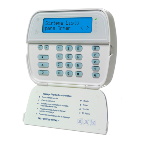
Inhep Digital Security IDS1632 Instructions for use

Installer Guide to Wiring and
Keypad Programming
I
N
H
E
P
D
I
G
I
T
A
L
S
E
C
U
R
I
T
Y
IDS
MANUAL NO. 700-256-02 C ISSUED JUNE 2005 VERSION 1.01
IDS1632
IDS1632

IDS1632INSTALLERMANUAL
IDS1632 INSTALLER MANUAL NO. 700-256-02C ISSUED JUNE 2005 VER 1.01
2
stnetnoC.
1
1. Introduction to the IDS1632 ............................. 4
1.1 Features of the IDS1632 ...................................... 5
2. Installation and Wiring ...................................... 6
3. End-of-Line Resistors/Tamper by Zone/Zone ..
Doubling ............................................................ 7
4. Box Tamper Input.............................................. 8
5. Installing an Expander Module ........................ 9
6. Connecting the Telephone Communicator .... 9
7. Programmable Outputs .................................... 9
8. Key-Switch or Remote Control Unit..............10
9. IDS Remote Receiver......................................10
10 Additional Technical Data .............................. 10
11. Radio Transmitter Connection ...................... 11
12. Hardware Reset Switch .................................. 11
13 Enrolling Keypads .......................................... 11
14. Defaulting Keypads ........................................12
15. Event Log......................................................... 13
16. Download Code ..............................................13
17. Programming Instructions ............................. 13
17.1 Introduction ........................................................ 13
17.2 Location Values ................................................. 13
18. Programming the Panel..................................14
18.1 Entering Program Mode .................................... 15
18.2 Programming Standard Locations ..................... 15
18.3 Programming Extended Locations .................... 16
18.4 Programming Bitmapped Location .................... 16
18.5 Incorrect Data Entries ........................................ 17
18.6 Programming Location Summary .................. 18
18.6.1 Zone Options ................................................. 18
18.6.2 System Options ............................................. 24
18.6.3 System Programmable Outputs ..................... 35
18.6.4 System Clock Options ................................... 39
18.6.5 Communicator Options .................................. 41
18.6.6 SMS Setup .................................................... 52
18.6.7 Partition Setup............................................... 54
18.6.8 User Options ................................................. 65
18.6.9 Programmable Output Options ...................... 72
18.6.10 Keypad Options............................................. 75
18.6.11 Installer Options ............................................. 77
Location Tables............................................................78

IDS1632INSTALLERMANUAL
IDS1632 INSTALLER MANUAL NO. 700-256-02C ISSUED JUNE 2005 VER 1.01 3
serugiF
Figure 1: Connection Diagram without Tamper per Zone 6
Figure 2: Tamper per Zone Connection .......................... 7
Figure 3: Zone Doubling Connection .............................. 8
Figure 4: Resistors used for Tamper per Zone or Zone .....
Doubling .......................................................... 9
Figure 5: Programmable Output Configuration ............. 10
Figure 6: Fire Detect Output Sequence ........................ 39
selbaT
Table 1: Value Represented by each Zone Indicator ... 14
Table 2: Hexadecimal Value........................................ 15
Table 3: Location / Zone defaults................................. 19
Table 4: Programmable Zone Types ........................... 20
Table 5: Programmable Ouput Numbering .................. 36
Table 6: Output Actions ............................................... 36
Table 7: Summary of System Event Driven......................
Programmable Outputs ................................. 38
Table 8: Summary of System Function Driven .................
Programmable Outputs ................................. 39
Table 9: Value for Day of the Week ............................. 40
Table 10: Standard Contact I.D Reporting Codes ......... 46
Table 11: Location Number - User Codes ..................... 64

IDS1632INSTALLERMANUAL
IDS1632 INSTALLER MANUAL NO. 700-256-02C ISSUED JUNE 2005 VER 1.01
4
2361SDIehtotnoitcudortnI.
1
The IDS1632 is a versatile, microprocessor based eight zone alarm
panel. It has eight partitions and can be expanded to thirty-two zones.
Most features are optional and may be programmed either directly
through the keypad or via the telephone system, using the IDS
download software and appropriate modem. There are sixteen on board
programmable burglary zones, a dedicated panic zone, monitored
siren output, auxiliary power outputs and eight programmable outputs
which may be programmed to perform various trigger/switching
functions.
For correct operation the IDS1632 must be used in conjunction with
the specified transformer/battery combination and appropriate
peripheral sensors and signalling devices.
I
N
H
E
P
D
I
G
I
T
A
L
S
E
C
U
R
I
T
Y
IDS

IDS1632INSTALLERMANUAL
IDS1632 INSTALLER MANUAL NO. 700-256-02C ISSUED JUNE 2005 VER 1.01 5
1
2361SDIehtfoserutaeF1.
1
RS485 keypad bus supports two eight zone expander modules,
one IDS remote receiver and up to sixteen keypads.
Sixteen programmable, end-of-line supervised zone inputs.
Expandable to thirty-two zones via keypad zones, zone
expander module, zone doubling or wireless expansion.
Eight partitions
Optional tamper reporting per zone using double end-of-line
resistors (12K and 4K7).
Fully programmable digital telephone communicator which
supports most industry standard formats.
Panel supports secure dial-in functionality using any DTMF
phone.
Eight programmable outputs on alarm panel. Expandable to
twelve when using Wired Zone Expander module.
Non volatile EEPROM memory retains all program and event log
data in the event of a total power failure.
Event log (one thousand events) date and time stamped.
Programmable loop response time.
Up and downloadable using IDS Windows based software, either
directly via RS232 or remotely using a modem
Excellent protection against lightning (provided by specialised
ìzap trackingî and transient suppressors).
Auto arm / disarm capability per partition and by day of the
week. The panel can be programmed to arm /disarm at a
pre-determined time.
Fax defeat / answering machine override.
Dual reporting provides for duplicated reporting to two independent
central base stations.
Dynamic battery self test.
Low battery cutout circuit.

IDS1632INSTALLERMANUAL
IDS1632 INSTALLER MANUAL NO. 700-256-02C ISSUED JUNE 2005 VER 1.01
6
gniriWdnanoitallatsnI.2
Please refer to Figure 1: Connection Diagram and familiarise yourself
with the following sections.
enoZreprepmaTtuohtiwmargaiDnoitcennoC.1erugiF
Line In
Line
Line
PhoneSirenRadio
+
+
Programmable Outputs
1
2
3
4
5
6
7
8
S
Radio Transmitter /
Communicator Power
To Radio Transmitter or Communicator
Hardware
Reset Switch
Battery
4A
Auxiliary Power 12 Volt
+
+
+
+
D-
D+
Keypad Zone Zone Zone Zone Zone Zone Zone
1
2
3
4
5
6
7
8
9
10
11
12
13
14
15
16
ZoneZone
P
GND
+12V
D-
D+
P
A
N
I
C
ZONE
Panic
Button
N/O
1
2
3
4
5
6
7
8
9
0
*
#
P
M
O
D
E
F
M
MAG SW N/C
MAG SW N/C
3
K3
3
K3
P
A
N
I
C
3
K3
Connect as required with
a 3k3 resistor in unused zones
3
K3
3
K3
NC
+
-
P.I.R.
NC
+
-
P. I .R .
NC
+
-
P.I.R.
3
K3
3
K3
NC
+
-
P.I.R.
Aux 1A
Siren 4A
PGM
DOOR
LED
Direct Download
Port
Box
Ta m p e r
16V AC
A
C Mains

IDS1632INSTALLERMANUAL
IDS1632 INSTALLER MANUAL NO. 700-256-02C ISSUED JUNE 2005 VER 1.01 7
/enoZybrepmaT/srotsiseReniL-fo-dnE.3 gnilbuoDenoZ
All zones must be end-of-line supervised. Any unused zones
must be terminated with a 3K3 resistor.
The end of line resistor must be placed inside or as close to the
sensor as possible.
If neither zone doubling nor tamper by zone are required the 3K3
resistor must be used.
For zone doubling or tamper per zone, the 4K7 and 12K end-of-
line resistors must be connected as per Figures 2 and 3.
noitcennoCenoZreprepmaT.2erugiF
Tamper operation is as follows:
If the panel is unarmed and a tamper condition occurs, the
siren will not sound but a tamper condition will be reported.
If the panel is armed and a tamper condition occurs an
audible alarm will register and a tamper condition will be
reported.
Panic zones always register panic and tamper conditions.
The colour codes for the 12K and 4K7 resistors are as per
in Figure 4.

IDS1632INSTALLERMANUAL
IDS1632 INSTALLER MANUAL NO. 700-256-02C ISSUED JUNE 2005 VER 1.01
8
noitcennoCgnilbuoDenoZ.3erugiF
The following limitations apply to zone doubling:
1. Only normally closed contacts (n/c) may be used.
2. If the zone input to the panel is short or open circuited at the
panel, both the zone and its double will be violated.
3. If the 12K resistor is ìopen circuitedî the primary
zone will indicate a violation i.e. assuming zone 8 is doubled in
this case zone 8 will be indicated as violated.
4. If the 4K7 resistor is ìopen circuitedî the secondary
zone will indicate a violation i.e. assuming the example in 3 above
zone 16 would indicate the violation.
5. The colour codes for the 4K7 and 12K resistors are shown in
Figure 4.
tupnIrepmaTxoB.4
The box tamper input does not require an end-of- line resistor and
requires a normally closed contact.

IDS1632INSTALLERMANUAL
IDS1632 INSTALLER MANUAL NO. 700-256-02C ISSUED JUNE 2005 VER 1.01 9
eludoMrednapxEnagnillatsnI.5
When installing an expander module refer to the document supplied
with the module. Note that only 1 expansion module is allowed.
gnilbuoDenoZroenoZreprepmaTrofdesusrotsiseR.4erugiF
rotacinummoCenohpeleTehtgnitcennoC.6
Refer to Figure 1. Connection Diagram.
For optimum lightning protection connect a low impedance earth
to the communicator earth input
Always connect the telephone communicator in line seizure
mode and never in parallel with the telephone. Ensure the
telephone receiver is connected to the communicator terminals
marked ìphoneî and the incoming line to the terminals marked
ìlineî.
stuptuOelbammargorP.7
A relay board must be used when any device requiring a high current is
connected to a programmable output. The programmable output
circuitry consists of a 12 volt source with a 56Ωseries resistor.
Current sink is via a 1000Ωresistor to negative. For information
purposes, the output circuitry for a single output is shown in Figure 5.

IDS1632INSTALLERMANUAL
IDS1632 INSTALLER MANUAL NO. 700-256-02C ISSUED JUNE 2005 VER 1.01
10
noitarugifnoCtuptuOelbammargorP.5erugiF
tinUlortnoCetomeRrohctiwS-yeK.8
A momentary key-switch or non-latching remote control receiver may
be connected to any zone to allow remote arm/disarm and remote
panic capability.
When using a key-switch or remote control unit a 3K3 resistor
must be connected between the zone input and ground.
Use only a spring-loaded momentary key-switch or non-latching
remote control unit.
revieceRetomeRSDI.9
An IDS Remote Receiver (PN 860-06-0002) may be connected to the
keypad bus. Using this facility allows remote arming and disarming of
the panel while providing user identification for a maximum of 238
remotes. It is possible to assign multiple remotes to a single user.
ataDlacinhceTlanoitiddA.0
1
A suitable transformer with an output voltage of 16 volts AC
±10% with a 16VA minimum rating must be used. A 32 VA
transformer is recommended for larger installations.
A 12V sealed lead acid battery with a minimum capacity of 7AH
must be used. The back up period after mains failure will depend

IDS1632INSTALLERMANUAL
IDS1632 INSTALLER MANUAL NO. 700-256-02C ISSUED JUNE 2005 VER 1.01 11
on the number of keypads, sensors and peripheral devices
connected to the system.
The panel can supply a total continuous current of 750mA to
peripheral devices such as keypads, remotes, receivers, passives
etc.
Connect a 12 volt self driven siren or piezo siren [not a horn
speaker] to the siren output.
noitcennoCrettimsnarToidaR.1
1
When connecting a radio transmitter utilize the TX terminal provided
on the P.C.B to supply power to the transmitter. (See Figure 1) This
output is protected by the 4 Amp battery fuse.
hctiwSteseRerawdraH.2
1
Should the need arise to return the panel to factory default, utilise the
hardware reset switch (see Figure 1).
The panel may be defaulted as follows. Remove both battery and AC
power from the panel. While depressing the reset switch reapply power
to the panel by either connecting the battery or the a.c. power.
Release the reset switch approximately 2 seconds after reapplying the
power. Factory default values will now be restored to all locations and
all attached keypad I.Dís will be defaulted.
Note: Once the reset switch has been disabled by programming a
10 into location 444 it will no longer be possible to default
the panel using the reset switch. The panel can only be
defaulted if a valid installer code is entered and a value of [0]
is entered into location 0.
sdapyeKgnillornE.3
1
A new panel supplied from the factory will have factory default values in
all locations (as indicated throughout this manual). Similarly new
keypads will have no ID assigned to them. It is however good practice
to default the system by using the reset switch prior to
commencement of programming. This will ensure that the above is
true and that no factory test values remain.

IDS1632INSTALLERMANUAL
IDS1632 INSTALLER MANUAL NO. 700-256-02C ISSUED JUNE 2005 VER 1.01
12
The keypad/s attached to a system as defaulted above will have no ID
and will therefore not communicate with the panel. This is indicated
by all keypad LEDís flashing simultaneously. In order to enroll a
keypad (thereby giving the keypad an ID) press the [#] key of the
keypad you wish to enroll. The enrolled keypad will now indicate the
alarm status. Repeat this process with the remaining keypads where
more than 1 keypad is used. The first keypad enrolled will have an ID
of 1, the second enrolled will have an ID of 2, the third an ID of 3 etc. A
maximum of 8 keypads may be used.
Note : If the keypad zone is to be used, consideration must be given
to the sequence in which keypads are enrolled as this affects
the LED zone designation. The keypad 1 will contain zone
16, keypad 2 will contain zone 15 etc. as per
section 14 in this manual.
If a keypad is replaced in a multi keypad system the new keypad
when enrolled will be assigned the first available slot. I.e. keypad 3 in
a 5 keypad system is replaced due to a fault. When the new keypad
is enrolled it will be allocated a value of 3. If in this case a new keypad
was added to the system (6th keypad), it would be assigned an ID of
6.
sdapyeKgnitluafeD.4
1
To default the I.D of a keypad(s):
1. Remove power to the keypad (or the whole panel if easier). Whilst
holding down the [ 1 ]and [ 3 ] keys restore the power to the
keypad.
2. All the keypad LEDís will flash simultaneously indicating that the
keypad has now been de-registered.
Note : In a multi keypad installation this process only
defaults the individual keypad at which this operation
was performed. Wait for five seconds and then press
the [#] hash key to allocate a new I.D to the
defaulted keypad. Keypad I.D’s are allocated
incrementally.
3. The I.D of any keypad can be interograted by viewing the data in
location 446 from the keypad of interest.

IDS1632INSTALLERMANUAL
IDS1632 INSTALLER MANUAL NO. 700-256-02C ISSUED JUNE 2005 VER 1.01 13
goLtnevE.5
1
A comprehensive log of the thousand most recent events are retained
in the non-volatile EEPROM. The log may be retrieved using the up/
download software. Alternatively it can be viewed using an LCD
keypad.
edoCdaolnwoD.6
1
The download code in conjunction with the installer code is required
for download access. The default download code is 9999. Using the
downloading software it is possible to program a location that will
either allow or disallow defaulting of the download code. This location
is only accessible using the download software. If the panel is
defaulted the download code will revert back to 9999. A value of [1] [0]
programmed into this location will prevent the download code from
being defaulted when defaulting the panel.
snoitcurtsnIgnimmargorP.7
1
noitcudortnI1.7
1
The panel can be programmed either via a keypad or via the up/
download software. Programming the panel by means of a LED
keypad is explained below:
Note: Before commencing programming it is advisable to read the
InstallerManualthoroughly.
seulaVnoitacoL2.7
1
All values within a program location will be displayed by the zone
indicators in binary coded decimal format i.e. zone indicators 1-4
indicate units (1ís) and zone indicator 5-8 indicate 10ís.
To read a binary value on the keypad sum the values represented by
each illuminated LED as shown in Table 1:

IDS1632INSTALLERMANUAL
IDS1632 INSTALLER MANUAL NO. 700-256-02C ISSUED JUNE 2005 VER 1.01
14
.rotacidnIenoZhcaeybdetneserpeReulaV1elbaT
s'1s'01
1enoZ 15enoZ 1
2enoZ 26enoZ 2
3enoZ 47enoZ 4
4enoZ 88enoZ 8
Binary values for Zones 1 - 4 are indicative of single unit values, whilst
binary values for Zones 5 - 8 are indicative of units of ten.
Example: Assume the following zone indicators are illuminated:
Zone 1, Zone 3 and Zone 5. Units are represented by
the sum of Zone 1 and Zone 3 (i.e 1 + 4) and tens of
units are represented by the value of Zone 5 (i.e. 1)
Thus the value indicated by the illuminated LED will
be shown below.
s'1s'01
1enoZ 15enoZ 1
3enoZ 4
eulaVyraniB5 eulaVyraniB1
Therefore the displayed value is 15.
lenaPehtgnimmargorP.8
1
For all programming procedures, the [(]key functions
as the [ENTER] key and the [#] hash key functions as a
[CLEAR] or an [EXIT] program key.
Invalid data entries are indicated by means of an error beep
consisting of 3 short beeps of the keypad buzzer.
There are two types of location categories:
ï Standard locations which are single tiered and do not
contain any sub-locations.
ï Extended locations which are double tiered and have
sub-locations.
Both standard and extended locations may contain further sub
categories refered to as bit mapped locations.

IDS1632INSTALLERMANUAL
IDS1632 INSTALLER MANUAL NO. 700-256-02C ISSUED JUNE 2005 VER 1.01 15
For both main categories clear visual keypad prompts are
provided which aid the programming process.
Some locations contain multi-digit data (e.g. a telephone
number, account codes etc.). To read the data stored in these
locations enter the location. Upon initial entry into the location the
first digit will be displayed by the zone indicators. Pressing the
[Panic] key will cause the next digit within the location to be
displayed.
Where a hexadecimal number must be programmed utilize the
[MODE] key as per Table 2 below:
eulaVlamicedaxeH2elbaT
eulaVxeH eulaVlamiceD sekortSyeK
A01 ]edoM[ yek]0[nehtyek
B11 ]edoM[ yek]1[nehtyek
C21 ]edoM[ yek]2[nehtyek
D31 ]edoM[ yek]3[nehtyek
E41 ]edoM[ yek]4[nehtyek
F51 edoM[ yek]5[nehtyek]
edoMmargorPgniretnE1.8
1
1. Ensure that all partitions are unarmed
2. Press the [#] hash key followed by the [INSTALLER CODE].
The default installer code is 9999
3. If a correct code has been entered the green READY indicator
will flash. Press the [(] star key and a long beep will
confirm entry into program mode.
snoitacoLdradnatSgnimmargorP2.8
1
1. Ensure the panel is in program mode - the READY indicator will
be flashing.
2. Enter the [LOCATION NUMBER] of the program location you
wish to view or change.
3. Press the [(] key. The READY indicator will continue
flashing and the AWAY indicator will illuminate.

IDS1632INSTALLERMANUAL
IDS1632 INSTALLER MANUAL NO. 700-256-02C ISSUED JUNE 2005 VER 1.01
16
4. The zone LEDís will display the data stored in the program
location in binary format.
5. Enter the [NEW DATA] followed by the [(] star key. A long beep
will indicate a valid entry and the AWAY indicator will extinguish.
6. If you do not wish to change the data press the [#] key.
The READY indicator will continue flashing and the AWAY
indicator will extinguish.
7. Repeat steps 2 - 5 until all the necessary locations have been
programmed.
8. Press the [#] hash key to exit program mode.
9. The READY indicator will stop flashing and the panel will return to
the standby mode.
snoitacoLdednetxEgnimmargorP3.8
1
1. Ensure that the panel is in program mode - the READY
indicator will be flashing.
2. Enter the [LOCATION NUMBER] of the program location that you
wish to view or change.
3. Press the [(]star key. The READY indicator will continue
flashing and the ARMED indicator will illuminate.
4. Enter the [SUB LOCATION NUMBER] for the program location
that you wish to view or change.
5. Press the [(] star key, a long beep indicates a valid data entry.
The READY indicator will continue flashing and the ARMED and
AWAY indicators will illuminate.
6. Enter the [NEW DATA] followed by the [(] star key. A long beep
will indicate a valid entry. The AWAY indicator will extinguish.
7. If you do not wish to change the data within this sublocation
press the [#] hash key. The READY indicator will continue
flashing and the AWAY indicator will extinguish.
8. Repeat steps 2 - 6 until all the necessary locations and their
sublocations have been programmed.
9. Press the [#] hash key twice to exit from program mode.
noitacoLdeppamtiBagnimmargorP4.8
1
1. A bitmapped location allows the installer to program multiple
panel features within a single location or sublocation. This is

IDS1632INSTALLERMANUAL
IDS1632 INSTALLER MANUAL NO. 700-256-02C ISSUED JUNE 2005 VER 1.01 17
achieved using the individual zone LEDs to indicate which
features are enabled or disabled.
2. By refering to the appropriate location reference tables the
installer can view the entire selection of features associated with
that location.
3. An illuminated zone LED indicates that a feature is enabled. An
extinguished LED indicates that a feature is disabled
4. The installer is able to toggle a selected LED indicator ON or OFF
by pressing the corresponding key followed by the [(] star key
5. Once a complete selection of features has been finalized, press
the [(] key to enter the selection to the location.
Example:
Location 40 allows the installer to select up to twelve trouble
conditions which may be displayed and reported. By default only AC
fail and low battery trouble conditions are enabled. Entering program
mode and viewing the contents of Location 40 it will be noted that the
zone [1] and zone [5] LEDs will be illuminated. All other zone LED
indicators will be extinguished. To enable the Comms Fail Trouble
Display (indicated by zone 2 LED) press the 2 key followed by the [(]
star key. A long beep will indicate a valid entry and the zone 2 LED
will illuminate indicating that Comms Fail Trouble Display has been
enabled. Continue selection (or deselection) of the desired trouble
conditions. Once a final selection has been made press the [(] star
key again to enter the selection. The AWAY indicator will extinguish
and a long beep will indicate acceptance of a valid data entry.
seirtnEataDtcerrocnI5.8
1
1. When programming either standard or extended locations any
attempt to enter invalid data will result in an error beep (3 short
beeps)
2. In the case of standard locations the AWAY indicator will remain
illuminated after the error beeps. Re-enter the correct data. There
is no need to press the [#] hash key.
3. In the case of extended locations the AWAY and ARMED
indicators will remain illuminated after the error beeps. Re-enter
the correct data. There is no need to press the [#] key.

IDS1632INSTALLERMANUAL
IDS1632 INSTALLER MANUAL NO. 700-256-02C ISSUED JUNE 2005 VER 1.01
18
yrammuSnoitacoLgnimmargorP6.8
1
A detailed description of each location and itís options follows.
0NOITACO
L
edoCresUretsaMrolenapehtfognitluafeD
eulaV noitcA
0resullA.seulavtluafedyrotcafehtotsnoitacolllateserlliW
lladna)4321edoCresUretsaM(:detluafedeboslalliwsedoc
.detluafedeblliws'didapyek
1edocresuretsaM.4321otedocresuretsamehttluafedlliW
.detluafedeboslalliwseitreporp
2sresUllastluafeD
3sdapyekllastluafeD
snoitpOenoZ1.6.8
1
23-1SNOITACO
L
puteSenoZlaudividnI
1NOITACOLBU
S
epyTenoZ
Program sub-location 1of locations 1 - 32 to define the zone
characteristics of each of the thirty-two zones. There are twelve zone
types. Table 4 provides a location/zone cross-reference together with
the default zone characteristics.
stluafedenoZ/noitacoL3elbaT
enoZ coL noitacoL-buS tluafeD epyTenoZ
11 1 tixE/yrtnE
22 2 rewolloF
61-361-34 tnatsnIelbiduA
23-7123-710delbasiD

IDS1632INSTALLERMANUAL
IDS1632 INSTALLER MANUAL NO. 700-256-02C ISSUED JUNE 2005 VER 1.01 19
Table 4 Provides a complete list of the different zone types together
with a description of their characteristics.
sepyTenoZelbammargorP4elbaT
eulaV epyTenoZ
0DELBASID
lortnocehtybderongisienozdelbasidafonoitaloivenoZA
.dapyekehtnodetacidniebtonlliwdnalenap
1ENOZTIXE/YRTNEYRAMIRP
yaledtixeehtgnirudderongieraenoztixE/yrtnEnafosnoitaloiV
nehwenoztixE/yrtnEnagnitaloiV.erudecorpgnimraehtfodoirep
deretnetonsiedoCresUdilavfI.yaledyrtneehtetaitinilliwdemra
eblliwnoitidnocmralana,seripxedoirepyaledyrtneehterofeb
gnimraretfaenoztixE/yrtnEnahguorhttixeoteruliaF.deretsiger
.mrAyatSotlenapehtesuaclliw
8ENOZTIXE/YRTNEYRADNOCES
detaloivsienozsihtfidetavitcaeblliwyaledyrtneyradnocesehT
.demrasilenapehtnehw
2ENOZREWOLLOF
eehtgnirudderongisienozrewolloFafonoitaloivA tixe/yrtn
doirepyaled rewollofehtaivtixe/retneotresuehtswollasiht(
lenapehtfienoztnatsninasaevaheblliwenozrewolloFA.)enoz
noitaloivotroirpdetaloivtonsienoztixE/yrtnEnadnademrasi
.enozrewollofehtfo
3ENOZYTIROIRP/CINAP
afonoitaloiva,tonrodemrasilenapehtrehtehwfosseldrageR
cinaparetsigerotlenaplortnocehtesuaclliwenozytiroirP
.noitidnoc
4ENOZTNATSNI
lliwenoztnatsninafonoitaloivehtdemrasilenapehtnehW
.noitidnocmralanaretsigerotlenaplortnocehtesuac
5ENOZMRASID/MRA
otlenapehtesuaclliwenozmrasiD/mrAnafonoitaloivehT
-nonrohctiws-yekyratnemomatcennoC.mrasidromrarehtie
.enozehtottinulortnocetomergnihctal

IDS1632INSTALLERMANUAL
IDS1632 INSTALLER MANUAL NO. 700-256-02C ISSUED JUNE 2005 VER 1.01
20
eulaV epyTenoZ
9ENOZYRTNEREWOLLOF
otnommocsienozyrtnenanehwdesusienozyrtnE/rewolloFA
rewollofasastcatidemraerasnoititraphtobnehW.snoititrapowt
tixe/yrtnenasastcatidemrasidsisnoititrapehtfoenofI.enoz
.enoz
01 ENOZERIF
fosseldragerdnuosotnerisehtesuaclliwenoZeriFafonoitaloiV
dnuoslliwnerisehT.tonrodemrasilenapehtrehtehw
noitarepotcerrocroF)ffodnoceseno,nodnoceseno(yltnattimretni
rewoprotcetederifasademmargorptuptuoelbammargorpa
.rotcetederifehtotrewoplortnocotdesuebtsumtuptuo
11 ENOZREPMAT
sseldragernoitatsesabehtotdetropereblliwenozsihtfonoitaloiV
demrasilenapehtfI.demrasidrodemrasilenapehtrehtehwfo
.detavitcaeblliwneriseht
21 ENOZMRALARUOH42
42afonoitaloiva,lenapehtfoetatsdemraehtfosseldrageR
.noitidnocmralanaretsigerlliwenozruoh
31 ENOZGNINRAW
esuaclliwenozgninrawafonoitaloiv,demrasilenapehtnehW
sititubgoltneveehtnideggolsinoitaloivehT.peebotneriseht detroperton dedulcniebyamsenozgninraW.noitatsesabehtot
.xirtamenozssorcehtfotrapsadesunehwdetnuoceblliwdna
41 ENOZMRAOTHSUP
lliwyaledtixeehtgnirudenozmraothsupafonoitaloiV
.lenapehtmrayletaidemmi
2NOITACOLBU
S
seitreporPenoZ
Note: Select all the options for each zone.
Shaded areas in the table indicate default values
This is a bitmapped location.
Table of contents
Other Inhep Digital Security Keypad manuals
