manuals.online logo
Brands
  1. Home
  2. •
  3. Brands
  4. •
  5. Channel Vision
  6. •
  7. Keypad
  8. •
  9. Channel Vision A0129 User manual

Channel Vision A0129 User manual

A0129
IR Keypad for A0350 & WA-350/WA-351
Pwr Mute
Vol
+
Vol
-
1
1
Pwr Mute
Vol
+
Vol
-
A0129 Keypad
3
A0129 ... Keypad controller for use with the A0350, WA-350/WA-351
Features:
• Controls Channel Vision’s A0350, WA-350, and WA-351
• Available in white
Power button.
Turns off the audio and
video playing in a zone.
Mute button.
Mutes the audio playing
in a zone (video will still
be present).
IR receiver.
Detects IR signals and repeats
through the IR system.
Volume +/- buttons.
Increases or decreases
the audio level in a zone.
2
Wiring the A0129 keypad...
Keypads connect to the through the RJ45 jacks on
the back panel of these products. Connections to the A0129 may be
accomplished either by using the RJ45 jack or the screw terminals provided
on the back side of the keypad. When using the RJ45 jacks, simply wire both
ends of the cable according to the TIA568A standard. When using the screw
terminals on the A0129, make sure to wire the RJ45 plug connecting to the
as shown below.
A0350, WA-350/WA-351
A0129
A0350/WA-35x
Front Rear
Pin 8: +VDC
Pin 7: Ground
Pin 4: IR signal
Pwr Mute
Vol
+
Vol
-
Pin 8: +VDC
Pin 7: Ground
Pin 4: IR signal
N.C.
Pin 7: Ground
Pin 8: +VDC
Pin 4: IR signal
Pwr Mute
Vol
+
Vol
-
A0129 Keypad
3
A0129 ... Keypad controller for use with the A0350, WA-350/WA-351
Features:
• Controls Channel Vision’s A0350, WA-350, and WA-351
• Available in white
Power button.
Turns off the audio and
video playing in a zone.
Mute button.
Mutes the audio playing
in a zone (video will still
be present).
IR receiver.
Detects IR signals and repeats
through the IR system.
Volume +/- buttons.
Increases or decreases
the audio level in a zone.
2
Wiring the A0129 keypad...
Keypads connect to the through the RJ45 jacks on
the back panel of these products. Connections to the A0129 may be
accomplished either by using the RJ45 jack or the screw terminals provided
on the back side of the keypad. When using the RJ45 jacks, simply wire both
ends of the cable according to the TIA568A standard. When using the screw
terminals on the A0129, make sure to wire the RJ45 plug connecting to the
as shown below.
A0350, WA-350/WA-351
A0129
A0350/WA-35x
Front Rear
Pin 8: +VDC
Pin 7: Ground
Pin 4: IR signal
Pwr Mute
Vol
+
Vol
-
Pin 8: +VDC
Pin 7: Ground
Pin 4: IR signal
N.C.
Pin 7: Ground
Pin 8: +VDC
Pin 4: IR signal
CHANNEL VISION
S
O
U
R
C
E
ZONE
POWER
MUTE
4
3
2
1
CAMERA
CATV
MOD
VOL
1
2
3
4
MODEL
A0505
POWER
TM
CHA NNEL VIS IO N
S
O
U
R
C
E
ZONE
POWER
MUTE
VOL
1
2
3
4
MODEL
A0501
POWER
Pwr Mute
Vol
+
Vol
-
Power button will
turn off/on zone
When the system
is powered back on
each zone will return
to its previous volume
level and source
selection.
Using the A050 remote control..
(Download IR codes at: www.channelvision.com and www.remotecentral.com)
5 designed to control your A0350, WA-35x.
Pwr Mute
Vol
+
Vol
-
Zone Power - Turns on/off the zone you are in
Power - Master power
(turns all zones on/off)
Mute - Mutes the audio
for the zone you are in
VOL - Controls volume
for the zone you are in
45
A0350
WA-350/WA-351
A0129
A0129
Keypad Input... Connect the A0129 here
CAT5 Audio Input... Connect the output of your CAT5 audio hub
here
Connection to A0350, WA-35x Amplifier
CAT5 Audio Input... Connect the output of your CAT5
audio hub here
Keypad Input... Connect the A0129 here
CHANNEL VISI O N
S
O
U
R
C
E
ZONE
POWER
MUTE
4
3
2
1
CAMERA
CATV
MOD
VOL
1
2
3
4
MODEL
A0505
POWER
TM
CHANNE L VISIO N
S
O
U
R
C
E
ZONE
POWER
MUTE
VOL
1
2
3
4
MODEL
A0501
POWER
Pwr Mute
Vol
+
Vol
-
Power button will
turn off/on zone
When the system
is powered back on
each zone will return
to its previous volume
level and source
selection.
Using the A050 remote control..
(Download IR codes at: www.channelvision.com and www.remotecentral.com)
5 designed to control your A0350, WA-35x.
Pwr Mute
Vol
+
Vol
-
Zone Power - Turns on/off the zone you are in
Power - Master power
(turns all zones on/off)
Mute - Mutes the audio
for the zone you are in
VOL - Controls volume
for the zone you are in
45
A0350
WA-350/WA-351
A0129
A0129
Keypad Input... Connect the A0129 here
CAT5 Audio Input... Connect the output of your CAT5 audio hub
here
Connection to A0350, WA-35x Amplifier
CAT5 Audio Input... Connect the output of your CAT5
audio hub here
Keypad Input... Connect the A0129 here
IR-4180 ... IR link cable. Can be used to transmit IR
A0501, A0502, or A0505 ... Remote control. Contains IR
codes for controlling the Amplified Wireless Audio Receiver
as well as many other Channel Vision audio products.
IR-2400 ... Plasma-Proof IR receiver.
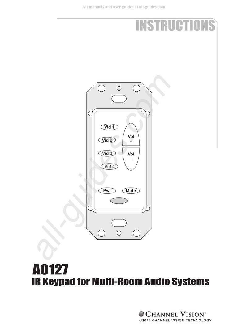
A0127 ... IR repeating keypad.
codes to operate the volume controls in the Amplified
Wireless Audio Receiver. You may also use a standard IR
receiver or a 3rd party keypad. When using a simple IR
receiver, you will need to use the A0505 remote control
which contains the IR codes to control the WA-350, WA-351,
and A0350. IR codes can be downloaded from
www.channelvision.com, or learned from an A0505 remote
control.
The A0127 contains the IR
Pwr Mute
Vid 1
Vid 2
Vid 3
Vid 4
Vol
+
Vol
-
TM
CHA NN E L VIS I ON
S
O
U
R
C
E
ZONE
POWER
MUTE
VOL
1
2
3
4
MODEL
A0501
POWER
Accessories & Complementary Products (sold separately)
In-wall, In-ceiling Speakers, and Free Standing
Speakers... Channel Vision offers a full line of premium
speakers. These speakers are perfect for whole-house music
or home theater applications.
Using the A0350 and A0129 in a Stand-alone System
The A0350 can be flush-mounted in a room to power in-wall speakers. By
connecting the audio outputs from an audio source to the RCA inputs of the
A0350, the audio signal will be amplified to the in-wall speakers. Most audio
sources only offer a fixed audio output, A0350 volume level can be adjusted by
using an A0129 keypad or by connecting an IR-2400 and using a compatible
remote such as model A0505. The RCA audio outputs on the back of the
A0350 can be connected to a powered subwoofer to add more bass to your
audio system.
A0129
A0350
Pwr Mute
Vol
+
Vol
-
TM
B y C H AN N E L V I S IO N
A ria
Local In
Active
Spkrs 24VDCIR In
Flush Mount Amplifier
Left Right
CD player
The keypad volume control will determine
the volume of the in-wall speakers as well
as the powered subwoofer.
Powered
Subwoofer
67
IR-4180 ... IR link cable. Can be used to transmit IR
A0501, A0502, or A0505 ... Remote control. Contains IR
codes for controlling the Amplified Wireless Audio Receiver
as well as many other Channel Vision audio products.
IR-2400 ... Plasma-Proof IR receiver.
A0127 ... IR repeating keypad.
codes to operate the volume controls in the Amplified
Wireless Audio Receiver. You may also use a standard IR
receiver or a 3rd party keypad. When using a simple IR
receiver, you will need to use the A0505 remote control
which contains the IR codes to control the WA-350, WA-351,
and A0350. IR codes can be downloaded from
www.channelvision.com, or learned from an A0505 remote
control.
The A0127 contains the IR
Pwr Mute
Vid 1
Vid 2
Vid 3
Vid 4
Vol
+
Vol
-
TM
CHA NN E L VIS I ON
S
O
U
R
C
E
ZONE
POWER
MUTE
VOL
1
2
3
4
MODEL
A0501
POWER
Accessories & Complementary Products (sold separately)
In-wall, In-ceiling Speakers, and Free Standing
Speakers... Channel Vision offers a full line of premium
speakers. These speakers are perfect for whole-house music
or home theater applications.
Using the A0350 and A0129 in a Stand-alone System
The A0350 can be flush-mounted in a room to power in-wall speakers. By
connecting the audio outputs from an audio source to the RCA inputs of the
A0350, the audio signal will be amplified to the in-wall speakers. Most audio
sources only offer a fixed audio output, A0350 volume level can be adjusted by
using an A0129 keypad or by connecting an IR-2400 and using a compatible
remote such as model A0505. The RCA audio outputs on the back of the
A0350 can be connected to a powered subwoofer to add more bass to your
audio system.
A0129
A0350
Pwr Mute
Vol
+
Vol
-
TM
B y C H AN N E L V I S ION
A ri a
Local In
Active
Spkrs 24VDCIR In
Flush Mount Amplifier
Left Right
CD player
The keypad volume control will determine
the volume of the in-wall speakers as well
as the powered subwoofer.
Powered
Subwoofer
67
500-300 revA
Channel Vision Technology will repair or replace any defect in
material or workmanship which occurs during normal use of this
product with new or rebuilt parts, free of charge in the USA, for one
year from the date of original purchase. This is a no hassle warranty
with no mail in warranty card needed. This warranty does not cover
damages in shipment, failures caused by other products not supplied
by Channel Vision Technology, or failures due to accident, misuse,
abuse, or alteration of the equipment. This warranty is extended only
to the original purchaser, and a purchase receipt, invoice, or other
proof of original purchase date will be required before warranty
repairs are provided.
Mail in service can be obtained during the warranty period by calling
(714) 424-6500. A Return Authorization number must be obtained
in advance and can be marked on the outside of the shipping carton.
This warranty gives you specific legal rights and you may have other
rights (which vary from state to state). If a problem with this product
develops during or after the warranty period, please contact Channel
Vision Technology, your dealer or any factory-authorized service
center.
Channel Vision products are not intended for use in medical,
lifesaving, life sustaining or critical environment applications.
Channel Vision customers using or selling Channel Vision products
for use in such applications do so at their own risk and agree to fully
indemnify Channel Vision for any damages resulting from such
improper use or sale.
1
Stripping and Connecting CAT5 Wire
Blade
CAT5
1. Place the CAT5 between the blade and the first notch of the J-110 tool.
CAT5 cable should be stripped with a proper stripping tool, such as Channel
Vision’s J-110 tool.
Slight
pressure
Rotate
1 turn only
2. Rotate the tool only once. Multiple
turns could damage the inner wires.
3. Inspect the inner wires for damage.
If any wires are cut start over at step 1.
Check for damage
Green/White - Left channel ground
Green - Left channel
Orange/White - Right channel ground
Blue - Signal
Blue/White - Status
Orange - Right channel
Brown/White - Ground
Brown - 24vDC
TIA-568A RJ-45 Modular Plug
Side view:
Top view:

Other manuals for A0129

1

Other Channel Vision Keypad manuals

Channel Vision A0127 User manual

Channel Vision

Channel Vision A0127 User manual

Channel Vision DS-Keypad User manual

Channel Vision

Channel Vision DS-Keypad User manual

Channel Vision A0127W User manual

Channel Vision

Channel Vision A0127W User manual

Channel Vision AB-124 User manual

Channel Vision

Channel Vision AB-124 User manual

Channel Vision AB-134 ABUS User manual

Channel Vision

Channel Vision AB-134 ABUS User manual

Channel Vision A0129 User manual

Channel Vision

Channel Vision A0129 User manual

Channel Vision A0127 User manual

Channel Vision

Channel Vision A0127 User manual

Channel Vision AB-124 User manual

Channel Vision

Channel Vision AB-124 User manual

Channel Vision A0125 User manual

Channel Vision

Channel Vision A0125 User manual

Popular Keypad manuals by other brands

AEI DK-9680 Series manual

AEI

AEI DK-9680 Series manual

Egardia Key pad installation guide

Egardia

Egardia Key pad installation guide

First Alert FA560VKP Installation and setup guide

First Alert

First Alert FA560VKP Installation and setup guide

Pima Hunter-Pro Series Installer Programming Guide

Pima

Pima Hunter-Pro Series Installer Programming Guide

Satel INT-TSG2 Quick installation guide

Satel

Satel INT-TSG2 Quick installation guide

Tekno K1 quick start guide

Tekno

Tekno K1 quick start guide

ERA KP700 installation guide

ERA

ERA KP700 installation guide

SpeakerCraft MODE 3.1 installation instructions

SpeakerCraft

SpeakerCraft MODE 3.1 installation instructions

Honeywell ADEMCO 6150RF Installation and setup guide

Honeywell

Honeywell ADEMCO 6150RF Installation and setup guide

FBII Omni-KP Installation and setup guide

FBII

FBII Omni-KP Installation and setup guide

Honeywell 6271C - Ademco TouchCenter Color Keypad Installation and user guide

Honeywell

Honeywell 6271C - Ademco TouchCenter Color Keypad Installation and user guide

Access Security Products KP401-IE user manual

Access Security Products

Access Security Products KP401-IE user manual

Magellan K636 User quick reference guide

Magellan

Magellan K636 User quick reference guide

Gecko in.k1000 Quick reference card

Gecko

Gecko in.k1000 Quick reference card

GSC 180 Series Handbook

GSC

GSC 180 Series Handbook

Alula RE152 PINPad quick start guide

Alula

Alula RE152 PINPad quick start guide

SDC EntryCheck 923P installation instructions

SDC

SDC EntryCheck 923P installation instructions

Xantech D5KP installation instructions

Xantech

Xantech D5KP installation instructions

manuals.online logo
manuals.online logoBrands
  • About & Mission
  • Contact us
  • Privacy Policy
  • Terms and Conditions

Copyright 2025 Manuals.Online. All Rights Reserved.