INIM Electronics V200 User manual
INIM ElectronicsV200 – Multicriteria smoke and temperature analogue addressable detector
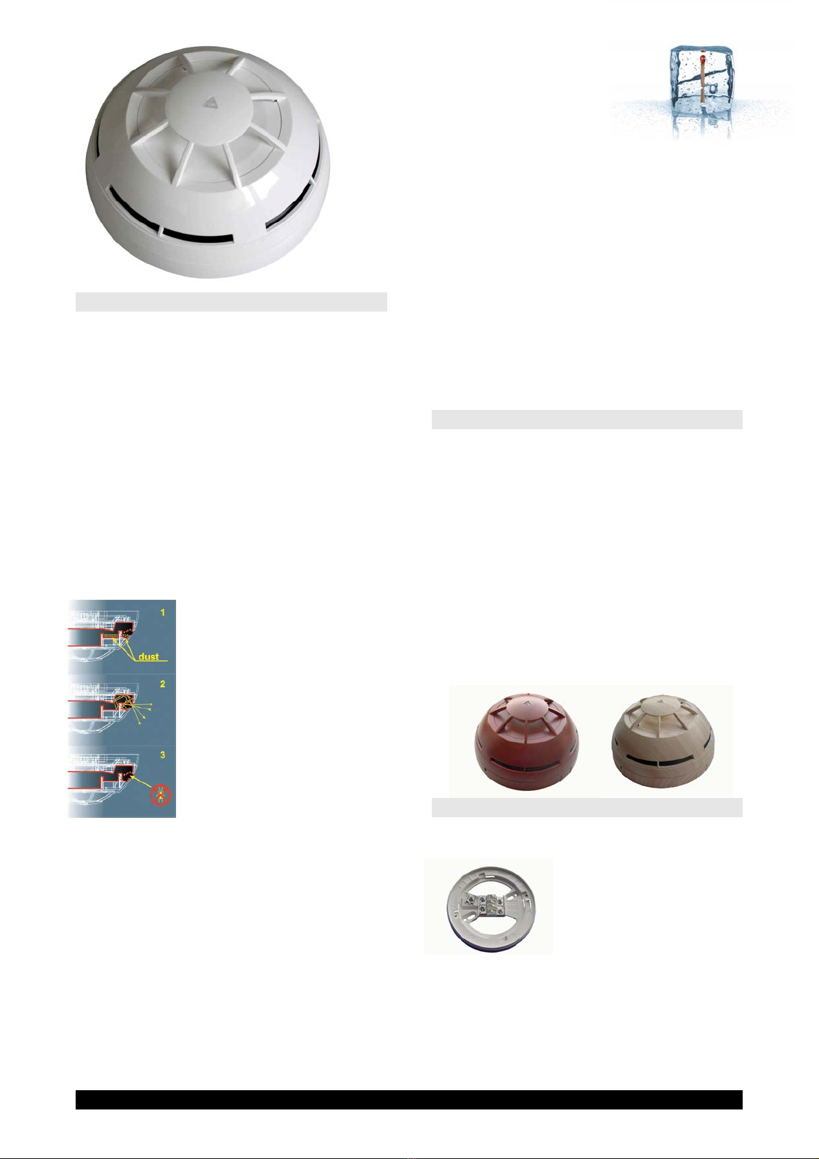
V200
ANALOGUE ADDRESSABLE
MULTICRITERIA
SMOKE+TEMPERATURE
DETECTOR
GENRAL DESCRIPTION
V200 is a multicrteria Analog addressable
detector which combine an optical smoke
detector based on Tyndall effect and a
temperature detector. The combination of
these two principle make the detector suitable
also for that fire risk where Smoke detector
are not normally used (i.e. fires with high
flames but low smoke emission etc.) The
innovative design of the baffle which the air
flow has to pass trough before enter in the
sampling chamber guarantee an high
immunity to environmental dust and a long
period between two consecutive cleaning of
the chamber. Each detector is equipped with a
Loop short circuit isolator.
The centrally positioned
status LED provides full
360° visibility. The LED can
signal an alarm condition
(red), a fault condition or
loop short circuit condition
(yellow). The led can also be
manually switched on from
control panel (green) for an
easy identification of the
detector. Detectors are
equipped with an output for
remote signalling (FI100). Detector sensitivity
can be adjusted directly from control panel,
by means of a magnet the detector can be
inducted in alarm state for test pourpose.
The detector can be fitted in the following
mounting bases:
•VB100 (standard base)
•VDBS100 (deep base)
•BLR100 (relay base)
•VBS100 (siren base)
V200 detectors can be used with the control
panels:
•SMARTLoop
•SMARTLight
Detector address (from 1 to 240) can be
selected:
•By means of VPU100 programmer
•Using the control panel self addressing
feature
MAIN FEATURES
•Approved according to EN54-7 ed
EN54-5 Standards by BSI (N°
KM96628)
•Approved accordin European
Construction Products Directive
(CPD) : 0086-CPD-504706
•Hi noise immunity
•Fast response
•3 Colour led located in the detector
center
•Output for remote LED driving
•Available with DECOR option
(Wood, marble etc.)
INSTALLATION
The detector muonting base must be installed
on the ceiling by means of 2 fisher screws and
the wires must be
connected to its terminal
boards. Position the
detector on its mounting
base and rotate it
clockwise, applying
gentle pressure. The detector will slot into
position. Press gently and continue to rotate
clockwise a few degrees until the detector is
firmly attached to its mounting base

INIM ElectronicsV200 – Multicriteria smoke and temperature analogue addressable detector
WIRING DIAGRAM
WIRING
Detector has to be connected to fire control
panel’s Loop by means of a 2 pole twisted
shielded cable (please refer to control panel
installation manual for more details regarding
wire gauge). The Negative pole of the Loop
enter in one of the two terminal board labelled
with “-“ on the mounting base, it do not mind
which one enter and which one exit. The
positive pole of the Loop enter and exit from
the same terminal board, the one labelled with
“R+” on the mounting base. The optional
remote led can be connected directly on the
mounting base terminal boards “+” (positive)
and “RA” (negative), this output is current
limited and can directly drive a LED.
TECHNICAL SPECIFICATIONS
PARAMETER VALUE
Operating Voltage 10-40 V d.c.
Current consumption 90 uA
MAX Current on remote LED 6 mA
Operating temperature range -30°C / +70°C
Umidity 95% RH
height (VB100 mounting base
included) 54 mm
Diameter 110 mm
Weight (VB100 base included) 130 g
INIM ELECTRONICS s.r.l.
Via Fosso Antico – Loc. Centobuchi
63033 MONTEPRANDONE
(AP) ITALY
Tel. +39 0735 705007
Fax +39 0735 704912
www.inim.biz
DISTRIBUTOR:
Other INIM Electronics Smoke Alarm manuals


Popular Smoke Alarm manuals by other brands


Geofire
Geofire Agrippa User instructions

System Sensor
System Sensor FAAST LT-200 FL20 Series Quick installation guide

System Sensor
System Sensor 1251B Installation and maintenance instructions

Kidde
Kidde 1296 user guide

Ei Electronics
Ei Electronics Ei146 Optical manual

Visonic
Visonic MCT-427 features and benefits