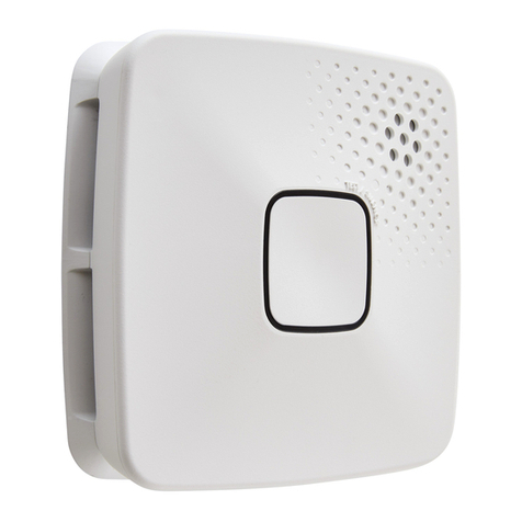
INIM Electronics Air2-FD100 Assembly instructions

"JS'%
8JSFMFTT TNPLF EFUFDUPS
E
EN 50131-1
EN 50131-5-3
EN 50130-4
EN 50130-5
INCERT
CEB T031
*OTUBMMBUJPO BOE QSPHSBNNJOH NBOVBM

Table of contents
1. Air2 system description 3
2. Air2-FD100 description 4
2.1 Description of parts 5
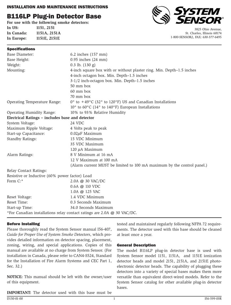
2.2 Air2-FD100 technical specifications 5
2.3 LED signallings from Air2-FD100 6
3. Installation of Air2-FD100 7
3.1 Enrolling a wireless device 7
3.2 Battery replacement 8
4. Programming wireless terminal 9
4.1 Wireless terminal parameters 9
4.2 Real-time 9
5. General information 10
5.1 About this manual 10
5.2 Manufacturer's details 10
5.3 Notes from the Manufacturer 10
5.4 Simplified EU Declaration of Conformity 10
5.5 Documents for the users 11
5.6 WEEE 11
2Installation and programming manual- 100-DRAFT

Air2-FD100 | © 2020 Inim Electronics S.r.l. 3
1. Air2 system description
All anti-intrusion systems INIM can manage the two-way wireless system Air2 characterized by a MHz carrier
frequency 868 MHz.
The system components Air2 are:
Air2-BS200/50 transceiver module, 50 terminals
Air2-BS200/30 transceiver module, 30 terminals
Air2-BS200/10 transceiver module, 10 terminals
Air2-KF100 4 button remote-control key
Air2-Ergo 4 button remote-control key
Air2-Pebble 4 button remote-control key
Air2-MC200 magnetic contact with shock and tilt sensor in white or brown
Air2-MC300 magnetic contact with two I/O terminals, in white or brown
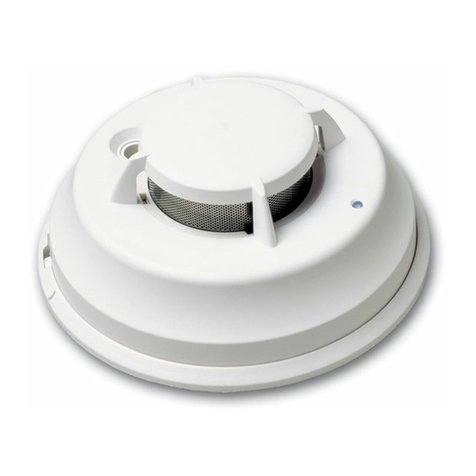
Air2-FD100 smoke detector
Air2-Aria/W keypad with graphic display
Air2-Hedera outdoor sounder, in white or chrome effect
Air2-Smarty/W indoor sounderflasher
Air2-DT200T dual technology curtain detector, in white or brown
Air2-XIR200W PIR detector, 12 m
Air2-XDT200W dual technology curtain detector
Air2-UT100 universal transceiver
Air2-ODI100W outdoor wireless dual-infrared detector
Air2-OTT100W outdoor wireless triple-technology detector
Technicalspecifications of the system Air2
Operatingfrequency
range 868.0 - 868.6 MHz
selectable channels 868.1, 868.3, 868.5 MHz
RF output power 25mW e.r.p.
Communication type Two-way
Modulation GFSK
Device supervision from 12 to 250 minutes
/PUF
In order tocomply with the EN 50131-1standards the alarm system supervisiontime must be below 120 minutes.

2. Air2-FD100 description
2. Air2-FD100 description
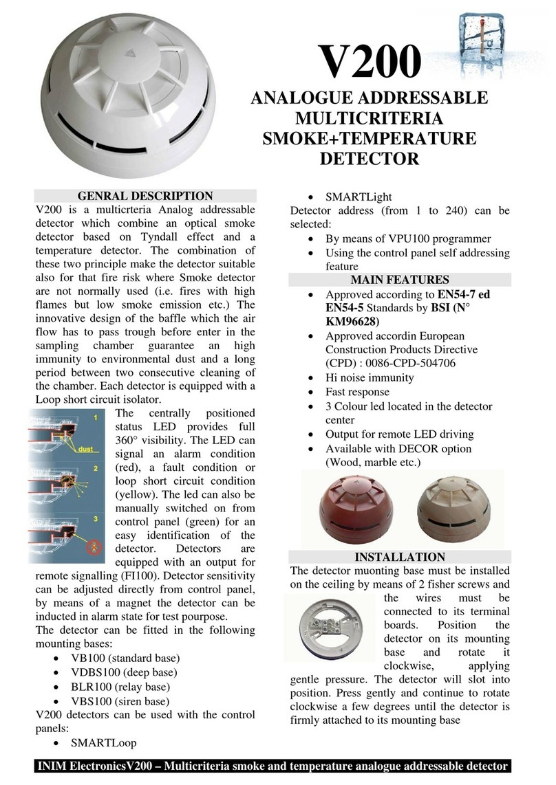
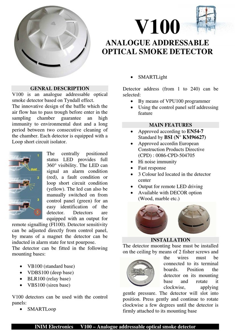
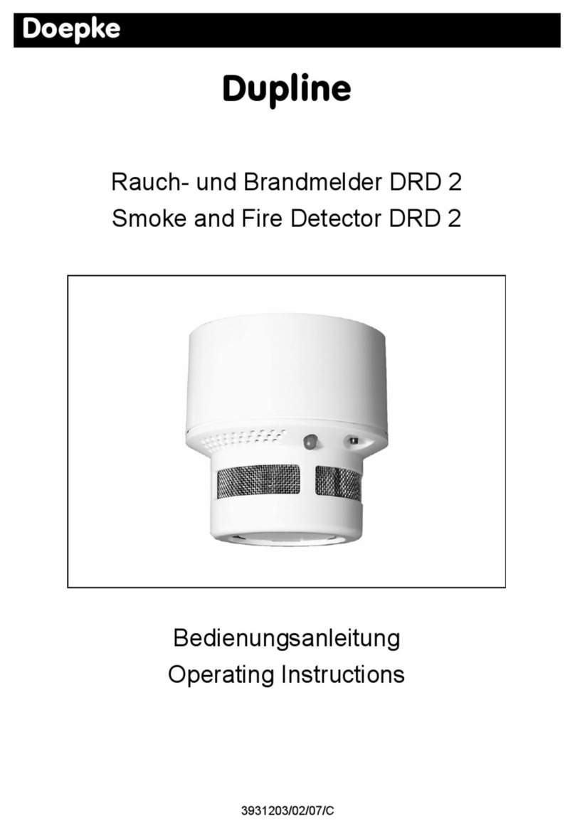
Air2-FD100 is capable of sensing the presence of smoke particles and thus detecting a fire in its early
stages.
Air2-FD100 is an optical smoke detector equipped with a sampling chamber based on light scattering mass
(Tyndall effect); in order to ensure the proper operating efficiency of the device, it must be installed away
from drafts and large objects which may alter the airflow to the sampling chamber.
"UUFOUJPO
Air2-FD100 is a smoke detector that can be used exclusively for the detection of
smoke in the protected area.
With the use of Air2-FD100 the intrusion control system INIM cannot be considered a
fire detection system.
The operating parameters of detectors can be changed and adapted to the environmental conditions, either
from the control panel or via the programming software.
The detector signals alarm status when the level of smoke in the protected environment reaches the fol-
lowing levels:
0.08 dB/m (pre-set mode)
0.10 dB/m
0.12 dB/m
0.15 dB/m
4Installation and programming manual- 100-DRAFT

Air2-FD100 | © 2020 Inim Electronics S.r.l. 5
2.1 Description of parts
2.1 Description of parts
<">LJ Detector
<#>LJ LED red/yellow/green
<$>LJ Battery
<%>LJ Tamper microswitch
<&>LJ ENROLL microswitch
<'>LJ Base
<(>LJ Mounting screw hole
2.2 Air2-FD100 technical specifications
Battery
type Lithium CR17450 3V
estimatedlife 3 years
“Low battery” fault voltage Less than 2.4V
Current draw
during standby 70µA

2. Air2-FD100 description
maximum 40mA
Operating environmental conditions
Temperature from -10 to +40 °C
Relative humidity ≤93% without condensation
Security rating 2
Environmentalclass II
Dimensions
Height (base included) 60mm
Diameter(base included) 114mm
Weight (base and battery included) 182 g
2.3 LED signallings from Air2-FD100
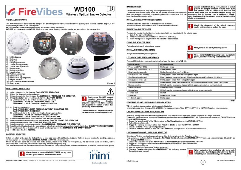
The tricolour LED (360° visibility) indicates the detector status.
Green - one flash every 15 seconds: detector operating properly.
Green - one flash every 40 seconds: low battery.
Yellow - On solid: fault present.
Yellow - flashing: sampling chamber contaminated (with dust, etc.).
Red - On solid: detector in alarm status.
6Installation and programming manual- 100-DRAFT

Air2-FD100 | © 2020 Inim Electronics S.r.l. 7
3.1 Enrolling a wireless device
3. Installation of Air2-FD100
1. Choose a suitable mounting placement.
2. Hold the base to the chosen mounting placement and mark the screw locations.
3. Insert the battery, ensure you respect the proper polarity.
4. Attach the battery cover.
5. Using the screws, secure the base and the tamper protection in position.
6. Position the detector over the base and, with minimum force, turn it clockwise until notch “A” aligns
with notch “B” (in order to attach the detector to the base); turn it still further until notch “A” aligns with
notch “C” (in order to allow the base to close the tamper microswitch).
7. Enroll the device.
3.1 Enrolling a wireless device
The enrolling procedure allows you to associate a wireless device INIM with the transceiver Air2-BS200
which acts in conjunction with the intrusion control panel.
This procedure varies depending on the control panelin use and the programming software or application:
1. Access the control panel programming.
2. Select the device to be enrolled in accordance with its type:
an input terminal, for a detector (motion detector, magnetic contact, etc.)
an output terminal, for an output device connected to a terminal of a magnetic contact Air2-
MC300

3. Installation of Air2-FD100
a keypad
a sounder/flasher
a key, for a remote control device, selecting as the associated reader the one simulated by the
transceiver
3. Set the device as “Wireless”.
4. Start the learning phase from the control panel.
5. Press the ENROLL button on the wireless device.
3.2 Battery replacement
When changing the battery, it is advisable to press the ENROLL button in order to be sure that the device is
synchronized with the wireless transceiver.
8Installation and programming manual- 100-DRAFT

Air2-FD100 | © 2020 Inim Electronics S.r.l. 9
4.1 Wireless terminal parameters
4. Programming wireless terminal
The programming of a wireless terminalcan only be done through the control panel programming software.
On accessing the software, it is necessary to open a solution, configuration of the real system to be
designed. Successively a terminal previously configured or to be configured as “wireless”must be selected.
After which it will be possible to access the device programming in order to select or change the device type
and its parameters.
4.1 Wireless terminal parameters
Use detector
LED The red LED on the device provides visual signalling of alarm or tamper conditions on the device itself.
Bypass tamper This option disables open/dislodgement tamper signalling.
Disable wireless
monitoring
Enabling this option (disabled at default), disables wireless monitoring on the detector.
In the event of the loss of the specific detector, no event will be generated and no fault signal will be signalled
on the keypad.
Disable detector
on partition dis-
arming
In order to increase battery life, the PIR detector will deactivate when the partitions it belongs disarm and
activate when the partitions it belongs to arm.
When the detector is deactivated it will not generate alarms.
From the moment the partitions arm, there may be a delay of up to 3 minutes before the detector receives the
activation command.
Alarm pulses
This is the number of pulses (each lasting as long as the programmed “Alarm pulse duration”) necessary to
generate a zone alarm event.
If this value is more than 1, you must also program the “Multi-pulse time” parameter.
Multi-pulse time
This parameter applies only when the “Alarm pulse num.” is higher than 1.
This is the window during which a number of alarm pulses must be detected (each lasting as long as the pro-
grammed “Alarm pulse duration”) equal to the value programmed for “Alarm pulses” in order for the system
to generate an alarm.
This time window can be expressed in seconds or minutes.
Alarm pulse dur-
ation
This is the length of time (after detection of alarm conditions) the zone will allow before generating an alarm.
Expressed in multiples of 15 milliseconds or minutes.
Detector sens-
itivity from 0.08 dB/m to 0.15 dB/m (default)
4.2 Real-time
For each configured device the software provides a direct software-to-device connection which allows visu-
alization of the real-time values of the following features of the wireless sounder:
Readinglevel The value read by each detector of the device is displayed on a bar which indicates the alarm threshold by
means of a colour change from green to red.
Signalrecep-
tion The series of notches represent the reception level of the wireless signal of the device as received by the trans-
ceiver Air2-BS200.
Battery
charge level Percentage of the device battery charge.
RF analysis Function to monitor the variation of the signal transmitted by the device and the background noise detected
through time.

5. General information
5. General information
5.1 About this manual
Manual code: DCMIINE0A2FD1008E
Revision: 100-DRAFT
Copyright: The information contained in this document is the sole property of Inim Electronics S.r.l.. Copy-
ing, reprinting or modification of this document, in part or as a whole, is not permitted without prior autho-
rization in writing from Inim Electronics S.r.l.. All rights reserved.
5.2 Manufacturer's details
Manufacturer:Inim Electronics S.r.l.
Production plant: Centobuchi, via Dei Lavoratori 10
63076 Monteprandone (AP),Italy
Tel.: +39 0735 705007
Fax: +39 0735 734912
E-mail info@inim.biz
Web: www.inim.biz
The persons authorized by the manufacturer to repair or replace the parts of this system have authorization
to work only on devices marketed under the brand Inim Electronics.
5.3 Notes from the Manufacturer
The devices Air2 are certified by IMQ-Sistemi di sicurezza (Italian certification body).
The information relating to the power-supply batteries required by the devices Air2 are provided in the fol-
lowing Technical Specification table.
The manufacturer cannot guarantee the declared battery life.
"UUFOUJPO
Do not use batteries other than those indicated by the manufactureras they may
explode.
5.4 Simplified EU Declaration of Conformity
Hereby, Inim Electronics S.r.l. declares that the radio equipment type Air2-FD100 is in compliance with Direc-
tive 2014/53/EU. The full text of the EU declaration of conformity is available at the following internet
address: www.inim.biz.
10 Installation and programming manual- 100-DRAFT

Air2-FD100 | © 2020 Inim Electronics S.r.l. 11
5.5 Documents for the users
5.5 Documents for the users
Declarations of Performance, Declarations of Conformity and Certificates concerning to Inim Electronics
S.r.l. products may be downloaded free of charge from the web address www.inim.biz, getting access to
Extended Access and then selecting "Certifications" or requested to the e-mail address info@inim.biz or
requested by ordinary mailto the address shown in this document.
Manuals may be downloaded free of charge from the web address www.inim.biz, getting access to the
reserved area, afterthe login, and then to the section of each product.
5.6 WEEE
Informative notice regarding the disposal of electrical and electronic equipment (appli-
cable in countries with differentiated waste collection systems)
The crossed-out bin symbol on the equipment or on its packaging indicates that the product must be
disposed of correctly at the end of its working life and should neverbe disposed of togetherwith gene-
ral household waste. The user, therefore, must take the equipment that has reached the end of its working
life to the appropriate civic amenities site designated to the differentiated collection of electrical and elec-
tronic waste. As an alternative to the autonomous-management of electrical and electronic waste, you can
hand over the equipment you wish to dispose of to a dealer when purchasing new equipment of the same
type. You are also entitled to convey for disposal small electronic-waste products with dimensions of less
than 25cm to the premises of electronic retail outlets with sales areas of at least 400m2, free of charge and
without any obligation to buy. Appropriate differentiated waste collection for the subsequent recycling of the
discarded equipment, its treatment and its environmentally compatible disposal helps to avoid possible
negative effects on the environment and on health and favours the re-use and/or recycling of the materials it
is made of.
Information about disposal of batteries and accumulators (applicable in Countries
with separate collection systems)
This marking on batteries and/or their manual and/or their packaging, indicates that batteries of this
products, at the end of their working life, should not be disposed of as unsorted municipal waste, but must
be object of a separate collection. Where marked, the chemical symbols Hg, Cd o Pb indicate that the bat-
tery contains mercury, cadmium or lead above the reference levels of the directive 2006/66/EC. If batteries
are not properly disposed of, these substances, together with other ones contained, can cause harm to
human health and to the environment. To protect human health and the environment, to facilitate treatment
and recycling of materials, separate batteries from other kind of waste and use the collection scheme stated
in your area, in accordance to current laws. Before disposing of the above, it's appropriate to remove them
from their holders avoiding to damage them or causing short circuits.

Via dei Lavoratori 10, Loc. Centobuchi
63076 Monteprandone (AP) ITALY
Tel. +39 0735 705007 _ Fax +39 0735 704912
DCMIINE0A2FD1008E-100-20200525-DRAFT
Table of contents
Other INIM Electronics Smoke Alarm manuals
