Stageline MPX-30DMP User manual

MPX-30DMP Bestellnummer 20.2760
BEDIENUNGSANLEITUNG • INSTRUCTION MANUAL • MODE D’EMPLOI
ISTRUZIONI PER L’USO • GEBRUIKSAANWIJZING • MANUAL DE INSTRUCCIONES • INSTRUKCJA OBSŁUGI
SIKKERHEDSOPLYSNINGER • SÄKERHETSFÖRESKRIFTER • TURVALLISUUDESTA
STEREO-DJ-MISCHPULT
MIT MP3-SPIELER
STEREO DJ MIXER WITH MP3 PLAYER
TABLE DE MIXAGE STÉRÉO DJ AVEC LECTEUR MP3
MIXER DJ STEREO CON LETTORE MP3

2
wwwwww..iimmggssttaaggeelliinnee..ccoomm
Bevor Sie einschalten …
Wir wünschen Ihnen viel Spaß mit Ihrem neuen Gerät
von „img Stage Line“. Bitte lesen Sie diese Bedienungs-
anleitung vor dem Betrieb gründlich durch. Nur so lernen
Sie alle Funktionsmöglichkeiten kennen, vermeiden
Fehlbedienungen und schützen sich und Ihr Gerät vor
eventuellen Schäden durch unsachgemäßen Gebrauch.
Heben Sie die Anleitung für ein späteres Nachlesen auf.
Der deutsche Text beginnt auf der Seite 4.
Before switching on …
We wish you much pleasure with your new “img Stage
Line” unit. Please read these operating instructions care-
fully prior to operating the unit. Thus, you will get to know
all functions of the unit, operating errors will be pre-
vented, and yourself and the unit will be protected
against any damage caused by improper use. Please
keep the operating instructions for later use.
The English text starts on page 7.
Avant toute installation …
Nous vous souhaitons beaucoup de plaisir à utiliser cet
appareil “img Stage Line”. Lisez ce mode dʼemploi entiè-
rement avant toute utilisation. Uniquement ainsi, vous
pourrez apprendre lʼensemble des possibilités de fonc-
tionnement de lʼappareil, éviter toute manipulation erronée
et vous protéger, ainsi que lʼappareil, de dommages éven-
tuels engendrés par une utilisation inadaptée. Conser-
vez la notice pour pouvoir vous y reporter ultérieurement.
La version française se trouve page 10.
Prima di accendere …
Vi auguriamo buon divertimento con il vostro nuovo
apparecchio di “img Stage Line”. Leggete attentamente
le istruzioni prima di mettere in funzione lʼapparecchio.
Solo così potete conoscere tutte le funzionalità, evitare
comandi sbagliati e proteggere voi stessi e lʼapparecchio
da eventuali danni in seguito ad un uso improprio. Con-
servate le istruzioni per poterle consultare anche in
futuro.
Il testo italiano inizia a pagina 13.
D
A
CH
GB
Antes de la utilización …
Le deseamos una buena utilización para su nuevo apa-
rato “img Stage Line”. Por favor, lea estas instrucciones
de uso atentamente antes de hacer funcionar el aparato.
De esta manera conocerá todas las funciones de la uni-
dad, se prevendrán errores de operación, usted y el apa-
rato estarán protegidos en contra de todo daño causado
por un uso inadecuado. Por favor, guarde las instruccio-
nes para una futura utilización.
La versión española comienza en la página 19.
Voor u inschakelt …
Wij wensen u veel plezier met uw nieuwe apparaat van
“img Stage Line”. Lees deze gebruikershandleiding gron-
dig door, alvorens het apparaat in gebruik te nemen.
Alleen zo leert u alle functies kennen, vermijdt u foutieve
bediening en behoedt u zichzelf en het apparaat voor
eventuele schade door ondeskundig gebruik. Bewaar de
handleiding voor latere raadpleging.
De Nederlandstalige tekst vindt u op pagina 16.
Przed uruchomieniem …
Życzymy zadowolenia z nowego produktu “img Stage
Line”. Dzięki tej instrukcji obsługi będą państwo w stanie
poznać wszystkie funkcje tego urządzenia. Stosując się
do instrukcji unikną państwo błędów i ewentualnego
uszkodzenia urządzenia na skutek nieprawidłowego
użytkowania. Prosimy zachować instrukcję.
Tekst polski zaczyna się na stronie 22.
Før du tænder …
Tillykke med dit nye “img Stage Line” produkt. Læs sik-
kerhedsanvisningerne nøje før ibrugtagning, for at
beskytte Dem og enheden mod skader, der skyldes for-
kert brug. Gem venligst denne betjeningsvejledning til
senere brug.
Sikkerhedsanvisningerne findes på side 25.
Innan du slår på enheten …
Vi önskar dig mycket glädje med din nya “img Stage
Line” produkt. Läs igenom säkerhetsföreskrifterna innan
enheten tas i bruk för att undvika skador till följd av
felaktig hantering. Behåll instruktionerna för framtida
bruk.
Säkerhetsföreskrifterna återfinns på sidan 25.
Ennen kytkemistä …
Toivomme Sinulle paljon miellyttäviä hetkiä uuden “img
Stage Line” laitteen kanssa. Ennen laitteen käyttöä pyy-
dämme Sinua huolellisesti tutustumaan turvallisuusoh-
jeisiin. Näin vältyt vahingoilta, joita virheellinen laitteen
käyttö saattaa aiheuttaa. Ole hyvä ja säilytä käyttöohjeet
myöhempää tarvetta varten.
Turvallisuusohjeet löytyvät sivulta 25.
F
B
CH
I
ENL
PL DK
SFIN
B

3
A
B
C
D
2
3
4
6
5
7
11
12
14
13
15
16
17
18
23 24 25 26 27
20
21
22
28
8
9
10
19
1

4
D
A
CH
Auf der ausklappbaren Seite 3 finden Sie
alle beschriebenen Bedienelemente und An-
schlüsse.
1 Übersicht der Bedienelemente
und Anschlüsse
1.1 Ober- und Vorderseite
1MP3-Spieler
AUSB-Buchse zum Einstecken eines USB-
Sticks oder zum Anschluss einer Fest-
platte mit eigener Stromversorgung
BSteckplatz für eine SD/SDHC-Karte
CDisplay, zeigt
in der oberen Zeile
– das angewählte Abspielmedium („U“ für
USB-Speicher, „S“ für SD/SDHC-Karte)
und die Nummer des Titels bzw. im
Modus „Stop“ die Anzahl der Titel
– den Dateinamen des Titels
in der unteren Zeile
– den Betriebsmodus („Play“, „Pause“
„Stop“)
– abwechselnd die bereits gespielte Zeit
des Titels und seine Gesamtlaufzeit
bzw. im Modus „Stop“ die Zeitanzeige
„000:00“
– „All“ bei ständiger Wiederholung aller
Titel oder „One“ bei ständiger Wiederho-
lung eines Titels
DBedientasten
– Taste
, um das Abspielen zu starten
und zu unterbrechen
– Taste , um das Abspielen zu beenden
– Taste , zum Umschalten zwischen
ständiger Wiederholung eines Titels (An-
zeige „One“) oder aller Titel (Anzeige
„All“)
– Tasten und , um einen Titel vor
oder zurück zu springen; für den schnel-
len Vor- oder Rücklauf im Titel die jewei-
lige Taste gedrückt halten
2Mikrofoneingang (kombinierte Buchse XLR/
6,3-mm-Klinke, sym.) für Kanal CH 1
3Regler GAIN für die Eingangsverstärkung,
für jeden Eingangskanal
4Klangregler, für jeden Eingangskanal
HIGH = Höhen, MID = Mitten, LOW = Tiefen
5Eingangswahlschalter,
für jeden Eingangskanal
CH 1 links Eingang MIC
rechts Eingang LINE 1/PHONO 1
CH 2 links Eingang PHONO 2
Mitte Eingang LINE 2
rechts MP3-Spieler
CH 3 links Eingang PHONO 3
rechts Eingang LINE 3
6Fader zum Einstellen des Kanalpegels,
für jeden Eingangskanal
7Taste TALK (mit Kontroll-LED) zum Stumm-
schalten der Kanäle CH 2 und CH 3 bei
Mikrofondurchsagen
8Schalter REVERSE zum Auswählen auf wel-
che Seite des Crossfaders (10) die Kanäle
CH 2 und CH 3 geschaltet werden
ON links Kanal CH 3, rechts Kanal CH 2
OFF links Kanal CH 2, rechts Kanal CH 3
9Schalter CURVE für das Überblendverhalten
des Crossfaders (10)
weiches, gleichmäßiges Überblenden
hartes Überblenden mit einem weiten
Bereich, in dem beide Kanäle gleich
laut zu hören sind
10 Überblendregler (Crossfader) für die Kanäle
CH 2 und CH 3
Wird die Überblendfunktion nicht benötigt,
den Crossfader in die Mitte schieben.
11 Betriebsanzeige
12 Stereo-Pegelanzeige für das mit dem Regler
MASTER (13) eingestellte Summensignal
13 Gesamt-Pegelregler MASTER: bestimmt den
Pegel des Summensignals, das über die
Ausgänge R BAL./L BAL. und MASTER (23)
ausgegeben wird
14 Balance-Regler für das mit dem Regler
MASTER (13) eingestellte Summensignal
15 Gesamt-Pegelregler BOOTH: bestimmt den
Pegel des Summensignals, das über den
BOOTH-Ausgang (24) ausgegeben wird
16 Lautstärkeregler für den Kopfhörerausgang
(19)
17 Vorhörtaste für jeden Eingangskanal (mit
Kontroll-LED): bei gedrückter Taste lässt sich
das zugehörige Kanalsignal vor dem Fader
(6) über einen Kopfhörer an der Buchse
(19) abhören (PFL = „Pre Fader Listening“).
18 Regler zur Auswahl des Abhörsignals für den
Kopfhörerausgang (19)
Position PFL
Vorhören der Kanäle, deren Taste PFL
SELECT (17) gedrückt ist
Position MASTER
Abhören der Signalsumme vor den Aus-
gangsreglern (13, 15)
19 6,3-mm-Klinkenbuchse zum Anschluss eines
Stereo-Kopfhörers (Impedanz min. 8 Ω)
1.2 Rückseite
20 Ein-/Ausschalter POWER
21 Netzbuchse zum Anschluss an eine Steck-
dose (230 V~/50 Hz) über das beiliegende
Netzkabel
22 Halterung für die Netzsicherung; eine ge-
schmolzene Sicherung nur durch eine glei-
chen Typs ersetzen
23 Stereo-Ausgänge R BAL./L BAL. (XLR-Ein-
baustecker, sym.) und MASTER (Cinch-
Buchsen) zum Anschluss des Verstärkers für
die Beschallung
Der XLR-Ausgang und der Cinch-Ausgang
können auch gleichzeitig zum Anschluss von
zwei Verstärkern verwendet werden. Der
Ausgangspegel wird mit dem Regler MAS-
TER (13) eingestellt.
24 Stereo-Ausgang BOOTH (Cinch-Buchsen)
für den Anschluss eines weiteren Verstär-
kers, z. B. für eine Monitoranlage oder eine
Nebenraum-Beschallung; der Ausgangspe-
gel wird mit dem Regler BOOTH (15) einge-
stellt
25 Stereo-Ausgang REC (Cinch-Buchsen) für
den Anschluss eines Aufnahmegerätes; der
Aufnahmepegel ist unabhängig von der Stel-
lung der Ausgangsregler (13, 15)
26 Stereo-Eingänge (Cinch-Buchsen) zum An-
schluss von Tonquellen an die Kanäle CH 1
bis CH 3
INPUT 2, INPUT 3:
Eingänge PHONO für Plattenspieler mit Mag-
netsystem,
Eingänge LINE für Geräte mit Line-Pegel-
Ausgang, z. B. CD-Spieler, Tapedeck, Radio
INPUT 1:
Der Eingang kann mit der daneben liegenden
Taste zwischen PHONO und LINE umge-
schaltet werden: siehe Position 27.
27 LINE/PHONO-Umschalter, um den daneben
liegenden Eingang für Kanal CH 1 auf Line-
Signalpegel (Taste ausgerastet) oder Phono-
Signalpegel (Taste gedrückt) zu schalten
28 Masse-Klemmschrauben GND für ange-
schlossene Plattenspieler
2 Hinweise für den
sicheren Gebrauch
Das Gerät entspricht allen relevanten Richtlinien
der EU und ist deshalb mit gekennzeichnet.
Beachten Sie auch unbedingt die folgenden
Punkte:
GDas Gerät ist nur zur Verwendung im Innen-
bereich geeignet. Schützen Sie es vor Tropf-
und Spritzwasser, hoher Luftfeuchtigkeit und
Hitze (zulässige Einsatztemperatur 0 – 40 °C).
GStellen Sie keine mit Flüssigkeit gefüllten Ge-
fäße, z. B. Trinkgläser, auf das Gerät.
GNehmen Sie das Gerät nicht in Betrieb und
ziehen Sie sofort den Netzstecker aus der
Steckdose,
1. wenn sichtbare Schäden am Gerät oder am
Netzkabel vorhanden sind,
2. wenn nach einem Sturz oder Ähnlichem der
Verdacht auf einen Defekt besteht,
3. wenn Funktionsstörungen auftreten.
Geben Sie das Gerät in jedem Fall zur Repa-
ratur in eine Fachwerkstatt.
GZiehen Sie den Netzstecker nie am Kabel aus
der Steckdose, fassen Sie immer am Stecker
an.
GVerwenden Sie für die Reinigung nur ein tro-
ckenes, weiches Tuch, niemals Wasser oder
Chemikalien.
GWird das Gerät zweckentfremdet, nicht richtig
angeschlossen, falsch bedient oder nicht fach-
gerecht repariert, kann keine Haftung für
daraus resultierende Sach- oder Personen-
schäden und keine Garantie für das Gerät
übernommen werden.
3 Einsatzmöglichkeiten
Das 3-Kanal-Mischpult MPX-30DMP ist für be-
liebige DJ-Anwendungen im privaten oder pro-
fessionellen Bereich geeignet. Das Gerät bietet
Anschlussmöglichkeiten für Geräte mit Line-
Pegel (z. B. CD-Spieler), Plattenspieler und ein
DJ-Mikrofon. Als zusätzliche Tonquelle steht der
integrierte MP3-Spieler zur Verfügung, mit dem
sich MP3-Audiodateien von USB-Speichern
(z. B. USB-Sticks) und SD/SDHC-Karten (max.
32 GB) abspielen lassen. Alle Tonquellen können
über einen Kopfhörer vorgehört werden („Pre
Fader Listening“).
Das Mischpult kann sowohl frei aufgestellt als
auch in ein Bedienpult eingebaut werden.
Soll das Gerät endgültig aus dem Be-
trieb genommen werden, übergeben
Sie es zur umweltgerechten Entsorgung
einem örtlichen Recyclingbetrieb.
WARNUNG Das Gerät wird mit lebensge-
fährlicher Netzspannung versorgt.
Nehmen Sie deshalb nie selbst
Eingriffe am Gerät vor. Durch un-
sachgemäßes Vorgehen besteht
die Gefahr eines elektrischen
Schlages.

4 Anschluss
Vor dem Anschluss bzw. vor dem Verändern von
Anschlüssen das Mischpult und die anzuschlie-
ßenden Geräte ausschalten.
1) Die Stereo-Tonquellen an die entsprechen-
den Cinch-Eingangsbuchsen (26) der Kanäle
CH 1 bis CH 3 anschließen (weiße Buchse
LEFT = linker Kanal; rote Buchse RIGHT =
rechter Kanal):
Geräte mit Line-Pegel-Ausgang (z. B. CD-
Spieler, Tapedeck, Radio) lassen sich an-
schließen an
– den Eingang LINE 1/PHONO 1 von Kanal
CH 1; die daneben liegende Taste (27)
muss dazu ausgerastet sein
– den Eingang LINE 2 von Kanal CH 2
– den Eingang LINE 3 von Kanal CH 3
Plattenspieler mit Magnetsystem lassen
sich anschließen an
– den Eingang LINE 1/PHONO 1 von Kanal
CH 1; die daneben liegende Taste (27)
muss dazu gedrückt sein
– den Eingang PHONO 2 von Kanal CH 2
– den Eingang PHONO 3 von Kanal CH 3
Ist am Anschlusskabel des Plattenspielers
ein separates Massekabel vorhanden, die-
ses mit einer Klemmschraube GND (28)
verbinden.
2) Ein Mikrofon lässt sich über einen XLR-Ste-
cker oder einen 6,3-mm-Klinkenstecker an
die symmetrisch beschaltete Buchse MIC (2)
anschließen.
3) Zum Anschluss von Verstärkern stehen
mehrere Stereoausgänge zur Verfügung:
– symmetrisch beschalteter XLR-Ausgang
R BAL./L BAL. und asymmetrisch beschal-
teter Cinch-Ausgang MASTER (23): An
einen dieser Ausgänge sollte der Haupt-
verstärker für die Beschallung angeschlos-
sen werden. Der XLR-Ausgang sollte be-
vorzugt verwendet werden, da die symme-
trische Signalübertragung einen besseren
Schutz gegen Störeinstrahlungen bietet,
die besonders bei längeren Anschlusska-
beln auftreten können.
Der XLR-Ausgang und der Cinch-Ausgang
können auch gleichzeitig zum Anschluss
von zwei Verstärkern verwendet werden.
– Ausgang BOOTH (24): Hier kann z. B. ein
Verstärker für eine Monitoranlage oder
für eine Nebenraum-Beschallung ange-
schlossen werden.
4) Sollen Tonaufnahmen gemacht werden, das
Aufnahmegerät an den Stereo-Ausgang
REC (25) anschließen. Der Aufnahmepegel
ist unabhängig von der Stellung der Aus-
gangsregler MASTER (13) und BOOTH (15).
5) Zum Vorhören der Eingangskanäle oder zum
Abhören des Summensignals vor den Aus-
gangsreglern MASTER und BOOTH kann
ein Kopfhörer (Impedanz min. 8 Ω) über
einen 6,3-mm-Klinkenstecker an den Stereo-
ausgang (19) angeschlossen werden.
6) Das beiliegende Netzkabel an die Netz-
buchse (21) anschließen und den Stecker in
eine Netzsteckdose (230 V~/50 Hz) ste-
cken.
5 Bedienung
Vor dem Einschalten die Ausgangsregler MAS-
TER (13) und BOOTH (15) auf Minimum stellen,
um Einschaltgeräusche zu vermeiden. Das
Mischpult wird mit dem Netzschalter POWER
(20) ein- und ausgeschaltet. Bei eingeschalte-
tem Gerät leuchtet die Betriebsanzeige ON (11).
5.1 Mischen der Tonquellen
Überblenden zwischen zwei Kanälen
1) Mit den Kippschaltern (5) für jeden Eingangs-
kanal die gewünschte Tonquelle anwählen:
CH 1 linke Position für das Mikrofon am Ein-
gang MIC
rechte Position für das Gerät am Ein-
gang LINE 1/PHONO 1
CH 2 linke Position für das Gerät am Ein-
gang PHONO 2
mittlere Position für das Gerät am Ein-
gang LINE 2
rechte Position für den integrierten
MP3-Spieler
CH 3 linke Position für das Gerät am Ein-
gang PHONO 3
rechte Position für das Gerät am Ein-
gang LINE 3
2) Zur Pegelangleichung und Klangkorrektur
der Eingangssignale, folgende Grundeinstel-
lungen durchführen:
a) Alle Kanalfader (6) auf Minimum stellen.
Alle Gain-Regler (3), Klangregler (4) und
den Crossfader (10) in die Mittelposition
stellen.
b) Leuchtet die LED über der Taste TALK (7),
die Taste zum Ausschalten der Talkover-
Funktion ausrasten.
c) Den Ausgangsregler MASTER (13) auf ca.
2⁄3des Maximums aufdrehen.
d) Ein Tonsignal (z. B. Musikstück) auf den
ersten benutzten Eingangskanal geben
und den zugehörigen Fader (6) bis ca. 2⁄3
des Maximums aufziehen.
e) Mit dem Regler GAIN (3) des Kanals den
Pegel so aussteuern, dass die Pegelan-
zeige (12) bei den lautesten Passagen im
0-dB-Bereich aufleuchtet. Den Klang mit
den Reglern HIGH, MID und LOW (4) ein-
stellen. Danach die Aussteuerung ggf. mit
dem Regler GAIN korrigieren. Nach der
Gain- und Klangeinstellung den Kanalfader
wieder auf Minimum stellen.
f) Die Schritte d) und e) für die übrigen ver-
wendeten Eingangskanäle wiederholen.
Hinweis: Diese Bedienschritte dienen nur als Hilfe-
stellung, es sind auch andere Vorgehensweisen zur
Grundeinstellung der Eingangskanäle möglich.
3) Nach der Grundeinstellung können die Ein-
gangssignale mit den Kanalfadern (6) im ge-
wünschten Lautstärkeverhältnis gemischt
oder ein- und ausgeblendet werden.
4) Für das Summensignal an den Ausgängen
R BAL./L BAL. und MASTER (23) mit dem
Ausgangsregler MASTER (13) die endgültige
Lautstärke einstellen und mit dem Regler
BAL (14) die Stereo-Balance. Der Signalpe-
gel lässt sich an der Pegelanzeige (12) able-
sen. In der Regel wird bei 0 dB eine optimale
Aussteuerung erreicht. Ist der Ausgangspe-
gel des Mischpults jedoch für den ange-
schlossenen Verstärker zu hoch oder zu nied-
rig, muss das Summensignal entsprechend
höher oder niedriger eingestellt werden.
Für einen an den Buchsen BOOTH (24)
angeschlossenen Verstärker die Lautstärke
mit dem Ausgangsregler BOOTH (15) ein-
stellen.
5) Mit dem Crossfader (10) kann zwischen den
Kanälen CH 2 und CH 3 übergeblendet wer-
den.
Mit dem Schalter REVERSE (8) die beiden
Kanäle dem Crossfader zuordnen:
Position ON
CH 2 rechte Seite des Crossfaders
CH 3 linke Seite des Crossfaders
Position OFF
CH 2 linke Seite des Crossfaders
CH 3 rechte Seite des Crossfaders
Mit dem Schalter CURVE (9) das Überblend-
verhalten des Crossfaders einstellen:
Position
weiches, gleichmäßiges Überblenden
Position
hartes Überblenden mit einem weiten Be-
reich, in dem beide Kanäle gleich laut zu
hören sind
6) Zur besseren Verständlichkeit einer Mikro-
fondurchsage kann die Taste TALK (7) ge-
drückt werden: Bei gedrückter Taste (LED
darüber leuchtet) sind die Kanäle CH 2 und
CH 3 stummgeschaltet.
5.2 Abhören über Kopfhörer
Die Eingangskanäle CH 1 bis CH 3 können ein-
zeln (oder auch gemeinsam) über einen Kopf-
hörer abgehört werden, auch wenn der zugehö-
rige Kanalfader (6) auf Minimum steht (PFL „Pre
Fader Listening“ = Abhören vor dem Fader).
Damit kann z. B. der nächste zu spielende Titel
ausgesucht werden.
Wahlweise ist es auch möglich, über den
Kopfhörer die Signalsumme, unbeeinflusst von
der Einstellung der Ausgangsregler MASTER
(13) und BOOTH (15), abzuhören.
1) Zum Vorhören eines Eingangskanals die zu-
gehörige Taste PFL SELECT (17) drücken,
die LED neben der Taste leuchtet.
2) Den Auswahlregler (18) für die Abhörfunktion
in die Position PFL schieben.
3) Die Kopfhörerlautstärke mit dem Regler PFL
(16) einstellen.
4) Soll das Summensignal abgehört werden,
den Auswahlregler für die Abhörfunktion in
die Position MASTER schieben. In den Zwi-
schenstellungen ist ein Mischsignal aus Ein-
gangskanal- und Summensignal zu hören.
5.3 Bedienung des MP3-Spielers
Der MP3-Spieler ist nach Inbetriebnahme des
Mischpults eingeschaltet. Ist kein Abspielme-
dium angeschlossen zeigt das Display (C):
Ist ein Abspielmedium angeschlossen, gibt das
Display nach dem Einlesen des Mediums hinter
dem jeweiligen Kennbuchstaben („U“ für USB-
Speicher, „S“ für SD/SDHC-Karte) die Gesamt-
anzahl der Titel an, z. B. für eine Speicherkarte
mit 132 Titeln:
VORSICHT Stellen Sie die Lautstärke der
Audioanlage und die Kopfhörer-
lautstärke nie sehr hoch ein. Hohe
Lautstärken können auf Dauer das
Gehör schädigen! Das Ohr ge-
wöhnt sich an hohe Lautstärken
und empfindet sie nach einiger Zeit
als nicht mehr so hoch. Erhöhen
Sie darum eine hohe Lautstärke
nach der Gewöhnung nicht weiter.
D
A
CH
5

D
A
CH
6
Diese Bedienungsanleitung ist urheberrechtlich für MONACOR ®INTERNATIONAL GmbH & Co. KG
geschützt. Eine Reproduktion für eigene kommerzielle Zwecke – auch auszugsweise – ist untersagt.
Sind zwei Abspielmedien angeschlossen, ist der
USB-Speicher angewählt. Zum Umschalten zwi-
schen zwei Medien muss das gerade ange-
wählte entfernt werden. Der MP3-Spieler schal-
tet dann automatisch auf das andere um. Er
schaltet auch immer automatisch auf das
Medium um, das neu angeschlossen wird.
Abspielmedium anschließen und entfernen:
– Einen USB-Stick in die USB-Buchse (A) ste-
cken oder eine Festplatte mit der USB-
Buchse verbinden. Eine angeschlossene
Festplatte darf nur eine Partition aufweisen
und muss über ein eigenes Netzgerät mit
Strom versorgt werden.
– Eine SD/SDHC-Karte (mit der abgeschrägten
Ecke voran und den Kontakten nach rechts)
so weit in den Steckplatz (B) stecken, bis sie
einrastet.
Um die Abspielmedien zu entfernen, den USB-
Speicher von der USB-Buchse trennen und die
Speicherkarte erst durch Hineindrücken entrie-
geln, dann herausziehen. USB-Speicher und
Speicherkarte sollten nicht während ihrer Wie-
dergabe entfernt werden.
Bedientasten (D)
Wiedergabe/Pause-Taste
Um das Abspielen zu starten, die Taste
drücken: Das Display zeigt „Play“, die Zeit-
anzeige daneben wechselt zwischen der
bereits gespielten Zeit des Titels und seiner
Gesamtlaufzeit. In der oberen Zeile wird der
Kennbuchstabe für das Abspielmedium („U“ =
USB-Speicher, „S“ = SD/SDHC-Karte) und
die Nummer des Titels angezeigt, dahinter der
Dateiname des Titels (als durchlaufende An-
zeige bei längeren Namen).
Um das Abspielen zu unterbrechen, die Taste
erneut drücken: Das Display zeigt „Pause“,
alle beweglichen Anzeigen „frieren ein“. Um
das Abspielen des Titels fortzusetzen, wieder
die Taste
drücken.
Stopp-Taste
Um das Abspielen zu beenden, die Taste
drücken: Das Display zeigt „Stop“, die Zeit-
anzeige wechselt auf „000:00“ und der aktuell
durchlaufende Dateiname „friert ein“. Anstelle
der Titelnummer wird die Gesamtanzahl der
Titel angegeben. Um das Abspielen mit dem
ersten Titel wieder zu starten, die Taste
drücken.
Wiederhol-Taste
Mit der Taste kann zwischen ständiger
Wiederholung aller Titel (Anzeige „All“) und
ständiger Wiederholung eines Titels (Anzeige
„One“) umgeschaltet werden.
Vorwärts/Rückwärts-Tasten und
Zum Sprung auf den nächsten Titel bzw. vor-
herigen Titel die jeweilige Taste kurz drücken.
Für den schnellen Vorlauf bzw. Rücklauf in-
nerhalb eines Titels die jeweilige Taste ge-
drückt halten.
6 Technische Daten
Eingänge
Empfindlichkeit/Impedanz
MIC: . . . . . . . . . . . . . . . 1 mV/650 Ω
PHONO 1: . . . . . . . . . . 2 mV/50 kΩ
PHONO 2, PHONO 3: . 1 mV/60 kΩ
LINE 1: . . . . . . . . . . . . . 70 mV/50 kΩ
LINE 2, LINE 3: . . . . . . 50 mV/10 kΩ
Ausgangspegel
R BAL./L BAL.: . . . . . . . 1 V*
MASTER: . . . . . . . . . . . 580 mV*
BOOTH: . . . . . . . . . . . . 500 mV
REC: . . . . . . . . . . . . . . 200 mV
Kopfhörerimpedanz: . . . . ≥ 8 Ω
Frequenzgang: . . . . . . . . . 20 – 20 000 Hz
Klirrfaktor: . . . . . . . . . . . . < 0,15 %
Störabstand: . . . . . . . . . . > 60 dB, unbewertet
Klangregelung
Tiefen: . . . . . . . . . . . . . +12 dB/
-
32 dB
bei 50 Hz
Mitten: . . . . . . . . . . . . . +12 dB/
-
32 dB
bei 1,2 kHz
Höhen: . . . . . . . . . . . . . +12 dB/
-
32 dB
bei 10 kHz
Anschlüsse
MIC, mono: . . . . . . . . . kombinierte Buchse
XLR/6,3-mm-Klinke
(sym.)
LINE, PHONO, stereo: . Cinch-Buchsen
R BAL./L BAL., stereo: . XLR-Einbaustecker
(sym.)
MASTER, stereo: . . . . . Cinch-Buchsen
BOOTH, stereo: . . . . . . Cinch-Buchsen
REC, stereo: . . . . . . . . Cinch-Buchsen
Kopfhörer, stereo: . . . . 6,3-mm-Klinken-
buchse
Stromversorgung: . . . . . . 230 V~/50 Hz
Leistungsaufnahme: . . . . max. 20 VA
Einsatztemperatur: . . . . . . 0 – 40 °C
Abmessungen: . . . . . . . . . 245 × 315 × 120 mm
Gewicht: . . . . . . . . . . . . . . 3 kg
* bei Anzeige 0 dB
Änderungen vorbehalten.

All operating elements and connections de-
scribed can be found on the fold-out page 3.
1 Operating Elements
and Connections
1.1 Front panel/front end
1MP3 player
AUSB port to connect a USB flash drive or a
hard disk with separate power supply
BSlot for an SD/SDHC card
CDisplay, to indicate
in the top line
– the replay medium selected (“U” for USB
storage medium, “S” for SD/SDHC card)
and the number of the title or, in the
“Stop” mode, the total number of titles
– the file name of the title
in the bottom line
– the operating mode
(“Play”, “Pause”, “Stop”)
– the time already played of the title alter-
nating with its total playing time or, in the
“Stop” mode, the time indication “000:00”
– “All” for constant repeat of all titles or
“One” for constant repeat of one title
DControl buttons
– button
to start/pause the replay
– button to stop the replay
– button to switch over between con-
stant repeat of one title (indication ”One”)
and constant repeat of all titles (indica-
tion “All”)
– buttons and to go to the next title
or to the previous title;
for fast forward/reverse within a title,
keep the corresponding button pressed
2Microphone input (combined jack XLR/
6.3 mm, bal.) for channel CH 1
3Control GAIN for the input amplification,
for each input channel
4Equalizer controls, for each input channel
HIGH, MID, LOW
5Input selector switch, for each input channel
CH 1 left input MIC
right input LINE 1/PHONO 1
CH 2 left input PHONO 2
centre input LINE 2
right MP3 player
CH 3 left input PHONO 3
right input LINE 3
6Fader to set the channel level,
for each input channel
7Button TALK (with indicating LED) to mute
the channels CH 2 and CH 3 during micro-
phone announcements
8Switch REVERSE to assign the channels
CH 2 and CH 3 to the right side or the left side
of the crossfader (10)
ON channel CH 3 on the left,
channel CH 2 on the right
OFF channel CH 2 on the left,
channel CH 3 on the right
9Switch CURVE for the behaviour of the
crossfader (10)
soft and smooth crossfading
sharp crossfading with a wide range in
which both channels are reproduced at
the same volume
10 Crossfader for the channels CH 2 and CH 3
When the crossfading function is not re-
quired, set the crossfader to mid-position.
11 Power LED
12 Stereo VU meter for the sum signal adjusted
with the control MASTER (13)
13 Overall level control MASTER: to define the
level of the sum signal sent to the outputs
R BAL./L BAL. and MASTER (23)
14 Balance control for the sum signal adjusted
with the control MASTER (13)
15 Overall level control BOOTH: to define the
level of the sum signal sent to the output
BOOTH (24)
16 Volume control for the headphone output
(19)
17 PFL (prefader listening) button for each input
channel (with indicating LED): When the but-
ton is pressed, it is possible to monitor the
corresponding channel signal ahead of the
fader (6) via headphones connected to the
jack (19).
18 Control to select the monitoring signal for the
headphone output (19)
position PFL
prefader listening to the channels of which
the button PFL SELECT (17) is pressed
position MASTER
monitoring of the signal sum ahead of the
output controls (13, 15)
19 6.3 mm jack to connect stereo headphones
(minimum impedance: 8 Ω)
1.2 Rear panel
20 POWER switch
21 Mains jack for connection to a socket (230 V~/
50 Hz) via the mains cable provided
22 Support for the mains fuse; always replace a
blown fuse by one of the same type
23 Stereo outputs R BAL./L BAL. (XLR chassis
plugs, bal.) and MASTER (RCA jacks) to con-
nect the amplifier for PA applications
The XLR output and the RCA output can also
be used at the same time to connect two
amplifiers. Adjust the output level with the
control MASTER (13).
24 Stereo output BOOTH (RCA jacks) to con-
nect another amplifier, e. g. for a monitoring
system or for PA applications in adjoining
rooms; adjust the output level with the control
BOOTH (15)
25 Stereo output REC (RCA jacks) to connect a
recorder; the recording level is independent
of the position of the output controls (13, 15)
26 Stereo inputs (RCA jacks) to connect audio
sources to the channels CH 1 to CH 3
INPUT 2, INPUT 3:
Input PHONO for turntables with magnetic
system
Input LINE for units with line level output, e. g.
CD player, tape deck, radio
INPUT 1:
To switch over the input between PHONO
and LINE, use the selector switch next to this
input see item 27.
27 LINE/PHONO selector switch; to switch the
input for channel CH 1 (next to the selector
switch) to line signal level (button disengaged)
or phono signal level (button engaged)
28 Clamp screws GND for ground connection of
turntables connected
2 Safety Notes
This unit corresponds to all relevant directives of
the EU and is therefore marked with .
Please observe the following items in any case:
GThe unit is suitable for indoor use only. Protect
it against dripping water and splash water,
high air humidity and heat (admissible ambi-
ent temperature range: 0 – 40 °C).
GDo not place any vessel filled with liquid on the
unit, e. g. a drinking glass.
GDo not operate the unit and immediately dis-
connect the mains plug from the socket
1. if the unit or the mains cable is visibly dam-
aged,
2. if a defect might have occurred after the
unit was dropped or suffered a similar acci-
dent,
3. if malfunctions occur.
In any case the unit must be repaired by
skilled personnel.
GNever pull the mains cable to disconnect the
mains plug from the socket, always seize the
plug.
GFor cleaning only use a dry, soft cloth; never
use water or chemicals.
GNo guarantee claims for the unit and no liabil-
ity for any resulting personal damage or mate-
rial damage will be accepted if the unit is used
for other purposes than originally intended, if it
is not correctly connected or operated, or if it
is not repaired in an expert way.
3 Applications
The 3-channel mixer MPX-30DMP is designed
for any private or professional DJ applications. It
offers connections for units with line level (e. g.
CD player), turntables and a DJ microphone.
The integrated MP3 player is an additional audio
source: It will replay MP3 audio files from USB
storage media (e. g. USB flash drives) and
SD/SDHC cards (32 GB max.). Prefader listen-
ing to all audio sources via headphones is avail-
able.
Set up the mixer on its own or install it into a con-
trol console.
4 Connection
Prior to making or changing any connections,
switch off the mixer and the units to be con-
nected.
1) Connect the stereo audio sources to the cor-
responding RCA input jacks (26) of the chan-
nels CH 1 to CH 3 (white jack LEFT; red jack
RIGHT):
Connect units with line level output (e. g.
CD player, tape deck, radio) to
– the input LINE 1/PHONO 1 of channel CH 1;
the button (27) next to this input must be
disengaged
– the input LINE 2 of channel CH 2
– the input LINE 3 of channel CH 3
If the unit is to be put out of operation
definitively, take it to a local recycling
plant for a disposal which is not harmful
to the environment.
WARNING
The unit uses dangerous mains
voltage. Leave servicing to skilled
personnel only. Inexpert handling
may result in electric shock.
7
GB

Connect turntables with magnetic system to
– the input LINE 1/PHONO 1 of channel CH1;
the button (27) next to this input must be
engaged
– the input PHONO 2 of channel CH 2
– the input PHONO 3 of channel CH 3
If there is a separate ground cable at the con-
nection cable of the turntable, connect this
ground cable to a clamp screw GND (28).
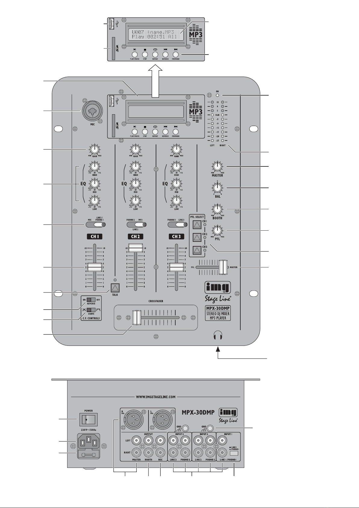
2) Connect a microphone via XLR plug or
6.3 mm plug to the balanced jack MIC (2).
3) To connect amplifiers, several stereo out-
puts are available:
– Balanced XLR output R BAL./L BAL. and
unbalanced RCA output MASTER (23):
Connect the main amplifier for PA applica-
tions to one of these outputs. The XLR out-
put should be preferred: The balanced sig-
nal transmission offers a higher protection
against interference which may occur par-
ticularly with long connection cables.
The XLR output and the RCA output can
also be used at the same time to connect
two amplifiers.
– Output BOOTH (24), e. g. to connect an
amplifier for a monitoring system or for
PA applications in adjoining rooms.
4) For audio recordings, connect the recorder
to the stereo output REC (25). The recording
level is independent of the position of the out-
put controls MASTER (13) and BOOTH (15).
5) For prefader listening to the input channels or
for monitoring the sum signal ahead of the
output controls MASTER and BOOTH, con-
nect headphones (minimum impedance: 8 Ω)
via 6.3 mm plug to the stereo output (19).
6) Connect the mains cable provided to the
mains jack (21) first, and then connect it to a
mains socket (230 V~/50 Hz).
5 Operation of the Mixer
Prior to switching on, set the output controls
MASTER (13) and BOOTH (15) to minimum to
prevent switching noise. To switch the mixer on
or off, use the POWER switch (20). When the
mixer has been switched on, the power LED ON
(11) lights up.
5.1 Mixing the audio sources
Crossfading between two channels
1) Use the toggle switches (5) to select the
desired audio source for each input channel:
CH 1 left position for the microphone at the
input MIC
right position for the unit at the input
LINE 1/PHONO 1
CH 2 left position for the unit at the input
PHONO 2
centre position for the unit at the input
LINE 2
right position for the integrated MP3
player
CH 3 left position for the unit at the input
PHONO 3
right position for the unit at the input
LINE 3
2) For level matching and sound correction of
the input signals, make the following basic
settings:
a) Set all channel faders (6) to minimum. Set
all gain controls (3), equalizer controls (4)
and the crossfader (10) to mid-position.
b) If the LED above the button TALK (7) lights
up, disengage the button to deactivate the
talkover function.
c) Set the output control MASTER (13) to
approx. 2⁄3of the maximum.
d) Feed an audio signal (e. g. music piece) to
the first input channel used and set the cor-
responding fader (6) to approx. 2⁄3of the
maximum.
e) Use the control GAIN (3) of the channel to
control the level in such a way that the 0 dB
range of the VU meter (12) lights up with
music peaks. Adjust the sound with the
controls HIGH, MID and LOW (4). If re-
quired, readjust the level control with the
control GAIN. After gain and sound have
been adjusted, set the channel fader to
minimum again.
f) Repeat steps d) and e) for the other input
channels used.
Note: These operating steps are merely an aid; for
basic setting of the input channels, you may also
proceed differently.
3) After the basic setting, mix the input signals
with the channel faders (6) to the desired vol-
ume ratio or fade them in or out, if required.
4) Use the MASTER control (13) to adjust the
definitive volume and the control BAL (14) to
adjust the stereo balance of the sum signal at
the outputs R BAL./L BAL. and MASTER (23).
The signal level is indicated on the VU meter
(12). Usually, there is an optimum level con-
trol at 0 dB: However, if the output level of the
mixer is too high or too low for the amplifier
connected, increase or decrease the sum sig-
nal accordingly.
For an amplifier connected to the jacks
BOOTH (24), adjust the volume with the out-
put control BOOTH (15).
5) The crossfader (10) is used for crossfading
between the channels CH 2 and CH 3.
Use the switch REVERSE (8) to assign the
two channels to the crossfader:
position ON
CH 2 right side of the crossfader
CH 3 left side of the crossfader
position OFF
CH 2 left side of the crossfader
CH 3 right side of the crossfader
Adjust the behaviour of the crossfader with
the switch CURVE (9):
position
soft and smooth crossfading
position
sharp crossfading with a wide range in
which both channels are reproduced at the
same volume
6) To make it easier to understand a micro-
phone announcement, press the button TALK
(7): When the button is engaged (LED above
the button lights up), the channels CH 2 and
CH 3 are muted.
5.2 Monitoring via headphones
It is possible to monitor the input channels CH 1
to CH 3 separately (or jointly) via headphones,
even if the corresponding channel fader (6) has
been set to minimum. (PFL = prefader listening;
i. e. monitoring ahead of the fader). This feature
is used, for example, to select the next title to be
replayed.
Alternatively, it is possible to monitor the sig-
nal sum, unaffected by the adjustment of the out-
put controls MASTER (13) and BOOTH (15), via
headphones.
1) For prefader listening to an input channel,
press the corresponding button PFL SELECT
(17). The LED next to the button lights up.
2) Slide the control for the monitoring function
(18) to the position PFL.
3) Adjust the headphone volume with the con-
trol PFL (16).
4) To monitor the sum signal, set the control
for the monitoring function to the position
MASTER. In the intermediate positions, a
mixed signal from the input channel signal
and the sum signal is reproduced.
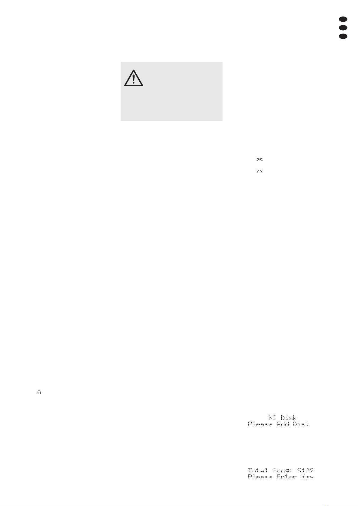
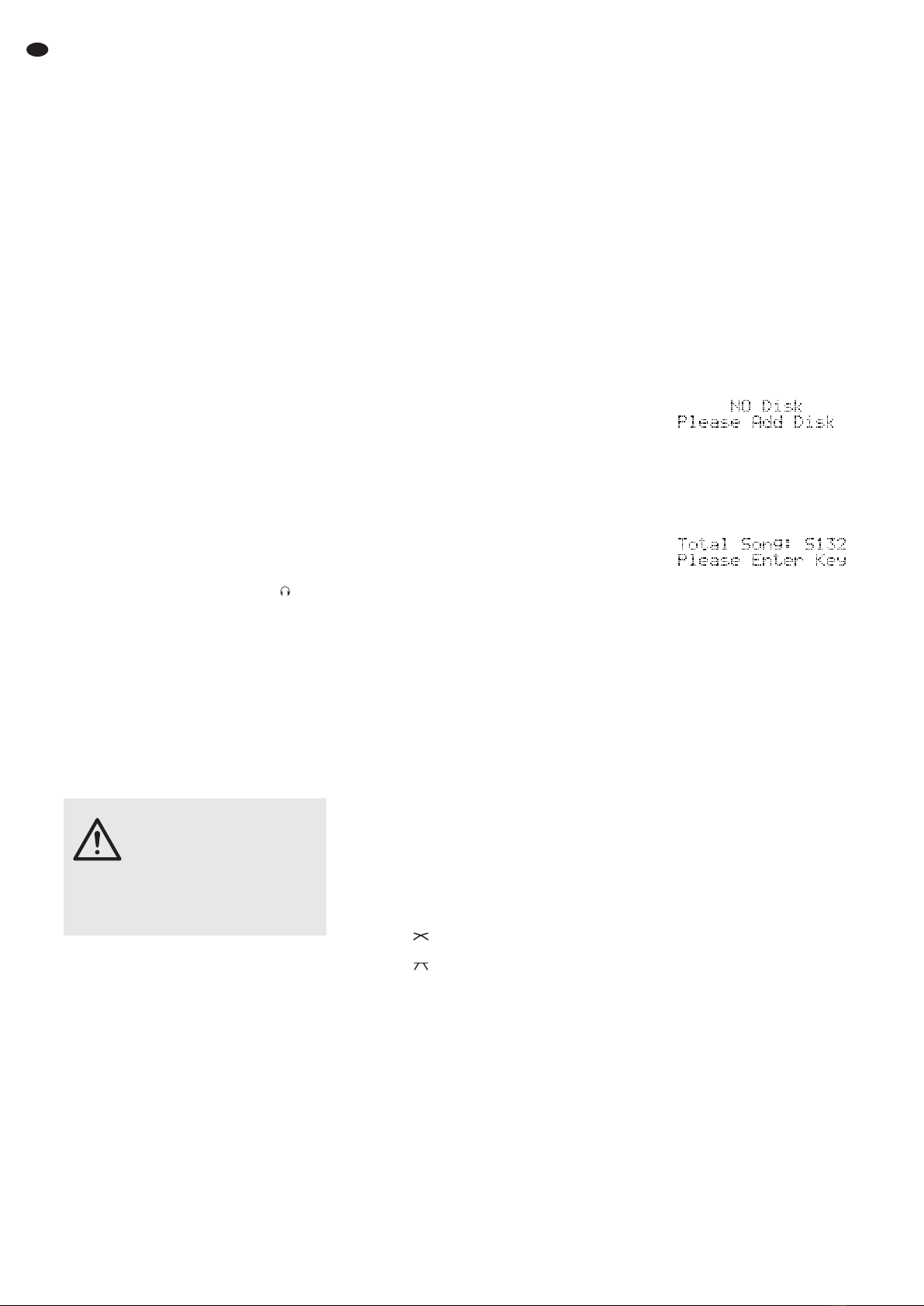
5.3 Operation of the MP3 player
After switching on the mixer, the MP3 player is
ready for operation. When no replay medium has
been connected, the display (C) indicates:
When a replay medium has been connected and
loaded, the display indicates the total number of
titles after the corresponding identification letter
(“U” for USB storage medium, “S” for SD/SDHC
card), e. g. for a memory card containing 132
titles:
When two replay media have been connected,
the player selects the USB storage medium. To
switch over from one medium to the other one,
disconnect the medium currently selected; the
MP3 player will then automatically select the
other medium. When a new medium is con-
nected, this medium is always selected automat-
ically.
Connecting/removing a replay medium:
– Connect a USB flash drive or a hard disk to
the USB port (A). The hard disk must only
have a single partition and must be supplied
with power via a separate power supply unit.
– Insert an SD/SDHC card (notched corner for-
ward and contacts to the right) into the slot (B)
until it engages.
To remove the replay media, disconnect the
USB storage medium from the USB port and
push in the memory card to unlock, then remove
it. Do not remove the USB storage medium or
the memory card while replaying.
Control buttons (D)
Play/Pause button
To start the replay, press the button
: The
display shows “Play”; the time indication next
to it switches over between the time already
played of the title and its total time. The top
line indicates the identification letter for the
medium (“U” for USB storage medium, “S” for
SD/SDHC card) and the number of the title
followed by the file name of the title (long
names will scroll through the display).
To pause the display, press the button
again: The display indicates “Pause”, all mov-
ing indications “freeze”. To continue the re-
play, press the button
again.
Stop button
To stop the replay, press the button . The dis-
play shows “Stop”, the time indication changes
to “000:00” and the file name scrolling through
the display “freezes”. Instead of the title num-
CAUTION Never adjust the audio system
and the headphones to a very high
volume. Permanent high volumes
may damage your hearing! Your
ear will get accustomed to high
volumes which do not seem to be
that high after some time. There-
fore, do not further increase a high
volume after getting used to it.
8
GB

ber, the total number of all titles is indicated. To
restart the first title, press the button
.
Repeat button
To switch over between constant repeat of
all titles (indication “All”) and constant repeat
of one title (indication “One”), press the but-
ton .
Forward/reverse buttons and
To go to the next title or the previous title,
briefly press the corresponding button. For
fast forward/reverse within a title, keep the
corresponding button pressed.
6 Specifications
Inputs
Sensitivity/Impedance
MIC: . . . . . . . . . . . . . . . 1 mV/650 Ω
PHONO 1: . . . . . . . . . . 2 mV/50 kΩ
PHONO 2, PHONO 3: . 1 mV/60 kΩ
LINE 1: . . . . . . . . . . . . . 70 mV/50 kΩ
LINE 2, LINE 3: . . . . . . . 50 mV/10 kΩ
Output level
R BAL./L BAL:: . . . . . . . 1 V*
MASTER: . . . . . . . . . . . 580 mV*
BOOTH: . . . . . . . . . . . . 500 mV
REC: . . . . . . . . . . . . . . 200 mV
Headphone impedance: . . ≥ 8 Ω
Frequency response: . . . . 20 – 20 000 Hz
THD: . . . . . . . . . . . . . . . . < 0.15 %
S/N ratio: . . . . . . . . . . . . . > 60 dB, unweighted
Equalizer controls
LOW: . . . . . . . . . . . . . . +12 dB/
-
32 dB
at 50 Hz
MID: . . . . . . . . . . . . . . . +12 dB/
-
32 dB
at 1.2 kHz
HIGH: . . . . . . . . . . . . . . +12 dB/
-
32 dB
at 10 kHz
Connections
MIC, mono: . . . . . . . . . combined jack
XLR/6.3 mm (bal.)
LINE, PHONO, stereo: . RCA jacks
R BAL./L BAL, stereo: . XLR chassis plugs
(bal.)
MASTER, stereo: . . . . . RCA jacks
BOOTH, stereo: . . . . . . RCA jacks
REC, stereo: . . . . . . . . RCA jacks
Headphone, stereo: . . . 6,3 mm jack
Power supply: . . . . . . . . . 230 V~/50 Hz
Power consumption: . . . . 20 VA max.
Ambient temperature: . . . 0 – 40 °C
Dimensions: . . . . . . . . . . 245 × 315 × 120 mm
Weight: . . . . . . . . . . . . . . . 3 kg
* when 0 dB is indicated
Subject to technical modification.
9
GB
All rights reserved by MONACOR ®INTERNATIONAL GmbH & Co. KG. No part of this instruction
manual may be reproduced in any form or by any means for any commercial use.

Vous trouverez sur la page 3, dépliable, les
éléments et branchements décrits.
1 Eléments et branchements
1.1 Face supérieure et face avant
1Lecteur MP3
APort USB pour brancher une clé USB ou
un disque dur avec alimentation propre
BInsert pour une carte SD/SDHC
CAffichage, indique :
dans la ligne supérieure
– le support de lecture sélectionné (“U”
pour support de mémoire USB, “S” pour
carte SD/SDHC) et le numéro du titre ou
en mode “Stop”, le nombre de titres
– le nom de fichier du titre
dans la ligne inférieure
– le mode de fonctionnement
(“Play”, “Pause”, Stop”)
– en alternance, la durée déjà lue du titre
et sa durée totale ou en mode “Stop”,
lʼaffichage de la durée “000:00”
– “All” pour une répétition continue de tous
les titres ou “One” pour une répétition
continue dʼun seul titre
DTouches de commande
– touche
pour démarrer et interrompre
la lecture
– touche pour arrêter la lecture
– touche pour commuter entre la répéti-
tion continue dʼun titre (affichage “One”)
ou de tous les titres (affichage “All”)
– touches et pour aller au titre sui-
vant ou au titre précèdent : pour une
avance ou un retour rapide, maintenez la
touche correspondante enfoncée
2Entrée micro (prise combinée XLR/jack 6,35,
sym) pour canal CH 1
3Réglage GAIN pour lʼamplification dʼentrée,
pour chaque canal dʼentrée
4Réglages égaliseur pour chaque canal dʼen-
trée
HIGH = aigus, MID = médiums, LOW =
graves
5Sélecteur dʼentrée
pour chaque canal dʼentrée
CH 1 gauche entrée MIC
droit entrée LINE1/PHONO 1
CH 2 gauche entrée PHONO 2
milieu entrée LINE 2
droit lecteur MP3
CH 3 gauche entrée PHONO 3
droit entrée LINE 3
6Fader pour régler le niveau du canal,
pour chaque canal dʼentrée
7Touche TALK (avec LED de contrôle) pour
couper le son des canaux CH 2 et CH 3 en
cas dʼannonces micro
8Interrupteur REVERSE pour sélectionner de
quel côté du crossfader (10) les canaux CH 2
et CH 3 sont commutés
ON à gauche : canal CH 3,
à droite : canal CH 2
OFF à gauche : canal CH 2,
à droite : canal CH 3
9Interrupteur CURVE pour le comportement
de transition du crossfader (10)
transition douce, régulière
transition dure avec une large plage
dans laquelle les deux canaux sont
audibles au même volume
10 Crossfader pour les canaux CH 2 et CH 3
Mettez le crossfader au milieu si vous nʼavez
pas besoin de la fonction crossfader
11 Témoin de fonctionnement
12 VU-mètre stéréo à LEDs pour le signal mas-
ter réglé avec le réglage MASTER (13)
13 Réglage général de niveau MASTER : déter-
mine le niveau du signal master qui sort des
sorties R BAL./L BAL. et MASTER (23)
14 Réglage de balance pour le signal master
réglé avec le réglage MASTER (13)
15 Réglage général de niveau BOOTH : déter-
mine le niveau du signal master qui sort de la
sortie BOOTH (24)
16 Réglage de volume pour la sortie casque
(19)
17 Touche de préécoute pour chaque canal
dʼentrée (avec LED de contrôle) ; si la touche
est enfoncée, on peut écouter le signal de
canal correspondant avant le fader (6) via un
casque relié à la prise (19) (PFL = “Pre
Fader Listening”)
18 Réglage pour sélectionner le signal dʼécoute
pour la sortie casque (19)
position PFL : préécoute des canaux dont la
touche PFL SELECT (17) est enfoncée
position MASTER : écoute du signal master
avant les réglages de sortie (13, 15)
19 Prise jack 6,35 pour brancher un casque sté-
réo (impédance minimale 8 Ω)
1.2 Face arrière
20 Interrupteur secteur marche/arrêt POWER
21 Prise secteur à relier à une prise 230 V~/
50 Hz via le cordon secteur livré
22 Porte fusible : tout fusible fondu doit impéra-
tivement être remplacé par un fusible de
même type
23 Sorties stéréo R BAL./L BAL. (XLR châssis
mâles, sym) et MASTER (RCA femelles)
pour brancher lʼamplificateur pour la sonori-
sation
La sortie XLR et la sortie RCA peuvent être
utilisées simultanément pour brancher deux
amplificateurs. Le niveau de sortie se règle
avec le réglage MASTER (13).
24 Sortie stéréo BOOTH (RCA femelles) pour
brancher un autre amplificateur, par exemple
pour une installation moniteur ou une sonori-
sation de pièce annexe ; le niveau de sortie
se règle avec le réglage BOOTH (15).
25 Sortie stéréo REC (RCA femelles) pour bran-
cher un enregistreur : le niveau dʼenregistre-
ment est indépendant de la position des
réglages de sortie (13, 15)
26 Entrées stéréo (RCA femelles) pour brancher
les sources audio aux canaux CH 1 à CH 3
INPUT 2, INPUT 3 :
Entrées PHONO pour platines disques avec
système magnétique
Entrées LINE pour appareils avec sortie
niveau ligne, par exemple lecteur CD, tape
deck, radio
INPUT 1
Lʼentrée peut être commutée entre PHONO
et LINE avec la touche située à côté :
position 27.
27 Sélecteur LINE/PHONO pour commuter lʼen-
trée située à côté pour le canal CH 1 sur le
niveau de signal ligne (touche non enclen-
chée) ou le niveau de signal Phono (touche
enclenchée)
28 Bornes à vis masse GND pour les platines
disques reliées
2 Conseils dʼutilisation
et de sécurité
Lʼappareil répond à toutes les directives néces-
saires de lʼUnion européenne et porte donc le
symbole .
Respectez scrupuleusement les points suivants :
GLʼappareil nʼest conçu que pour une utilisation
en intérieur. Protégez-le des éclaboussures,
de tout type de projections dʼeau, dʼune humi-
dité dʼair élevée et de la chaleur (température
ambiante admissible 0 – 40 °C).
GEn aucun cas, vous ne devez pas poser dʼob-
jet contenant du liquide ou un verre sur lʼap-
pareil.
GNe faites pas fonctionner lʼappareil et débran-
chez le cordon secteur immédiatement dans
les cas suivants :
1. lʼappareil ou le cordon secteur présente des
dommages visibles.
2. après une chute ou accident similaire, vous
avez un doute sur lʼétat de lʼappareil.
3. des dysfonctionnements apparaissent.
Dans tous les cas, les dommages doivent être
réparés par un technicien spécialisé.
GNe débranchez jamais lʼappareil en tirant sur
le cordon secteur ; retirez toujours le cordon
secteur en tirant la fiche.
GPour le nettoyage, utilisez un chiffon sec et
doux, en aucun cas de produits chimiques ou
dʼeau.
GNous déclinons toute responsabilité en cas de
dommages corporels ou matériels résultants
si lʼappareil est utilisé dans un but autre que
celui pour lequel il a été conçu, sʼil nʼest pas
correctement branché ou utilisé ou sʼil nʼest
pas réparé par une personne habilitée ; en
outre, la garantie deviendrait caduque.
3 Possibilités dʼutilisation
La table de mixage 3 canaux MPX-30DMP est
conçue pour des applications DJ profession-
nelles ou privées. Lʼappareil propose des possi-
bilités de branchement pour des appareils avec
niveau ligne (par exemple lecteur CD), des pla-
tines disques et un microphone DJ. Comme
source audio supplémentaire, le lecteur MP3
intégré est disponible, il permet de lire des
fichiers audio MP3 de supports de mémoire USB
(par exemple clés USB) et cartes SD/SDHC
(32 GO max.). Via un casque, on peut faire une
préécoute de toutes les sources audio (“Pre
Fader Listening”).
La table de mixage peut être posée librement ou
intégrée dans un pupitre.
Lorsque lʼappareil est définitivement retiré
du service, vous devez le déposer dans
une usine de recyclage de proximité pour
contribuer à son élimination non polluante.
AVERTISSEMENT Lʼappareil est alimenté par
une tension dangereuse. Ne
touchez jamais lʼintérieur de
lʼappareil car, en cas de mau-
vaise manipulation, vous pou-
vez subir une décharge élec-
trique.
10
F
B
CH

4 Branchements
Avant dʼeffectuer les branchements ou de modi-
fier les branchements existants, éteignez la
table de mixage et les appareils à relier.
1) Reliez les sources audio stéréo aux prises
dʼentrée RCA correspondantes (26) des
canaux CH 1 à CH 3 (prise blanche LEFT =
canal gauche, prise rouge RIGHT = canal
droit) :
Appareils avec sortie niveau ligne (par
exemple lecteur CD, tape deck, radio) peu-
vent être reliés à :
– lʼentrée LINE 1/PHONO 1 de canal CH 1 :
la touche à côté (27) ne doit pas être
enclenchée
– lʼentrée LINE 2 de canal CH 2
– lʼentrée LINE 3 de canal CH 3
Platines disques avec système magné-
tique peuvent être reliées à
– lʼentrée LINE1/PHONO 1 de canal CH 1 : la
touche à côté (27) doit être enclenchée
– lʼentrée PHONO 2 de canal CH 2
– lʼentrée PHONO 3 de canal CH 3
Si sur le cordon de branchement de la platine
disque, un cordon masse séparé existe,
reliez-le à une borne GND (28).
2) Vous pouvez relier un microphone via une
fiche XLR mâle ou une fiche jack 6,35 à la
prise symétrique MIC (2).
3) Pour brancher des amplificateurs, plusieurs
sorties stéréo sont disponibles :
– sortie XLR symétrique R BAL./L BAL. et
sortie RCA asymétrique MASTER (23) : il
faut relier lʼamplificateur principal de sono-
risation à une de ces sorties. Il est recom-
mandé de privilégier la sortie XLR car la
transmission symétrique de signaux pro-
pose une meilleure protection contre les
interférences pouvant survenir avec de
longs câbles de branchement.
La sortie XLR et la sortie RCA peuvent être
utilisées simultanément pour brancher
deux amplificateurs.
– sortie BOOTH (24) : on peut relier ici un
amplificateur pour une installation moni-
teur ou pour une sonorisation de pièce
annexe.
4) Si vous souhaitez faire des enregistrements
audio, reliez lʼenregistreur à la sortie stéréo
REC (25). Le niveau dʼenregistrement est
indépendant de la position des réglages de
sortie MASTER (13) et BOOTH (15).
5) Pour faire une préécoute des canaux dʼen-
trée ou écouter le signal master avant les
réglages de sortie MASTER et BOOTH, on
peut relier un casque (impédance minimale
8 Ω) via une fiche jack 6,35 mâle à la sortie
stéréo (19).
6) Reliez le cordon secteur livré à la prise (21) et
à une prise secteur 230 V~/50 Hz.
5 Utilisation
Avant dʼallumer la table de mixage, mettez les
réglages de sortie MASTER (13) et BOOTH (15)
sur le minimum pour éviter tout bruit de commu-
tation. Allumez et éteignez la table de mixage
avec lʼinterrupteur secteur POWER (20), le
témoin de fonctionnement ON (11) brille lorsque
la table est allumée.
5.1 Mixage des sources audio –
fondu enchaîné entre deux canaux
1) Avec les interrupteurs à bascule (5) sélec-
tionnez pour chaque canal dʼentrée la source
audio souhaitée :
CH 1 position gauche pour le micro à lʼen-
trée MIC
position droite pour lʼappareil à lʼentrée
LINE1/PHONO1
CH 2 position gauche pour lʼappareil à lʼen-
trée PHONO 2
position médiane pour lʼappareil à lʼen-
trée LINE 2
position droite pour le lecteur MP3
intégré
CH 3 position gauche pour lʼappareil à lʼen-
trée PHONO 3
position droite pour lʼappareil à lʼentrée
LINE 3
2) Pour adapter le niveau et faire les corrections
de tonalité des signaux dʼentrée, effectuez
les réglages de base suivants :
a) Réglez sur le minimum tous les faders de
canaux (6). Mettez sur la position médiane
tous les réglages de gain (3), égaliseurs
(4) et le crossfader (10).
b) Si la LED au-dessus de la touche TALK (7)
brille, désenclenchez la touche pour dés-
activer la fonction Talkover.
c) Mettez le réglage de sortie MASTER (13)
sur 2⁄3environ du maximum.
d) Appliquez un signal audio (par exemple
morceau de musique) sur le premier canal
dʼentrée utilisé et mettez le fader corres-
pondant (6) à 2⁄3environ du maximum.
e) Avec le réglage GAIN (3) du canal, réglez
le niveau de telle sorte que le VU-mètre
(12) brille dans la plage 0 dB pour des pas-
sages élevés. Réglez la tonalité avec les
réglages HIGH, MID et LOW (4). Ensuite,
corrigez si besoin avec le réglage GAIN.
Une fois les réglages de gain et de tonalité
effectués, mettez le fader du canal sur le
minimum.
f) Répétez les points d) et e) pour les autres
canaux dʼentrée utilisés.
Conseil : Les points ne sont quʼune aide, il existe
dʼautres manières de procéder pour faire le réglage
de base des canaux dʼentrée.
3) Après le réglage de base, on peut mixer les
signaux dʼentrée avec les faders des canaux
(6) dans le rapport de volume souhaité ou les
faire entrer et sortir.
4) Pour le signal master aux sorties R BAL./
L BAL. et MASTER (23), réglez le volume
définitif avec le réglage de sortie MASTER
(13) et réglez la balance stéréo avec le
réglage BAL (14). Le niveau de signal est
visible sur le VU-mètre (12). En règle géné-
rale, on a un réglage optimal dans la plage
0 dB. Si le niveau de sortie de la table de
mixage est trop élevé ou trop bas pour lʼam-
plificateur relié, le signal master doit être aug-
menté ou diminué en conséquence.
Pour un amplificateur relié aux prises
BOOTH (24), réglez le volume avec le
réglage de sortie BOOTH (15).
5) Avec le crossfader (10), vous pouvez faire un
fondu enchaîné entre les canaux CH 2 et
CH 3.
Avec lʼinterrupteur REVERSE (8), attribuez
les deux canaux au crossfader :
Position ON
CH 2 côté droit du crossfader
CH 3 côté gauche du crossfader
Position OFF
CH 2 côté gauche du crossfader
CH 3 côté droit du crossfader
Avec le sélecteur CURVE (9), réglez le com-
portement de transition du crossfader :
Position
transition douce et régulière
Position
transition dure avec une plage large dans
laquelle les deux canaux sont audibles au
même volume
6) Pour une meilleure compréhension dʼune
annonce micro, vous pouvez enfoncer la
touche TALK (7) : si la touche est enfoncée
(la LED au-dessus brille), le son des canaux
CH 2 et CH 3 est coupé.
5.2 Ecoute via un casque
On peut faire une écoute des canaux dʼentrée
CH 1 à CH 3 séparément (ou ensemble) via un
casque même si le fader correspondant (6) est
sur le minimum (PFL “Pre fader Listening” =
écoute avant le fader). On peut ainsi rechercher
le prochain titre à lire.
Il est également possible dʼécouter via le
casque, le signal master non influencé par le
réglage des réglages de sortie MASTER (13) et
BOOTH (15).
1) Pour faire une préécoute dʼun canal dʼentrée,
appuyez sur la touche PFL SELECT (17) cor-
respondante, la LED à côté de la touche
brille.
2) Mettez le sélecteur (18) pour la fonction
écoute sur la position PFL.
3) Réglez le volume du casque avec le réglage
PFL (16).
4) Si vous souhaitez faire une écoute du signal
master, mettez le sélecteur pour la fonction
écoute sur la position MASTER. Dans les
positions intermédiaires, on peut entendre un
signal de mixage venant du canal dʼentrée et
du signal master.
5.3 Utilisation du lecteur MP3
Le lecteur MP3 est allumé une fois la table de
mixage en service. Si aucun support de lecture
nʼest relié, lʼaffichage (C) indique :
Si un support de lecture est relié, lʼaffichage
indique, après la reconnaissance du support,
derrière la lettre correspondante (“U” pour sup-
port de mémoire USB, “S” pour carte SD/SDHC)
le nombre total de titres, par exemple pour une
carte mémoire avec 132 titres :
ATTENTION Ne réglez jamais le volume de
lʼinstallation audio et du casque
trop fort. Un volume trop élevé
peut, à long terme, générer des
troubles de lʼaudition. Lʼoreille
sʼhabitue à des volumes élevés et
ne les perçoit plus comme tels au
bout dʼun certain temps. Nous
vous conseillons donc de régler le
volume et de ne plus le modifier.
11
F
B
CH

12
F
B
CH
Notice dʼutilisation protégée par le copyright de MONACOR ®INTERNATIONAL GmbH & Co. KG.
Toute reproduction même partielle à des fins commerciales est interdite.
Si deux supports de lecture sont reliés, le sup-
port de mémoire USB est sélectionné. Pour
commuter entre deux supports, il faut retirer le
support actuellement sélectionné. Le lecteur
MP3 commute alors automatiquement sur lʼau-
tre. Il commute automatiquement sur le support
qui est à nouveau branché.
Branchement et éjection dʼun support de
lecture
– Mettez une clé USB dans le port USB (A) ou
branchez un disque dur au port USB. Un
disque dur relié ne doit avoir quʼune seule par-
tition et doit être alimenté par son propre bloc
secteur.
– Mettez une carte SD/SDHC (coin oblique vers
lʼavant et contacts vers la droite) dans lʼinsert
(B) jusquʼà ce quʼelle sʼenclenche.
Pour retirer les supports de lecture, débranchez
le support de mémoire USB du port USB et pour
la carte mémoire, appuyez dessus pour la déver-
rouiller puis retirez-la. Le support de mémoire
USB et la carte mémoire ne doivent pas être reti-
rés pendant la lecture.
Touches de commande (D)
Touche lecture/pause
Pour démarrer la lecture, appuyez sur la
touche
; lʼaffichage indique “Play”, lʼaffi-
chage de durée à côté commute entre la
durée déjà lue du titre et sa durée totale. Dans
la ligne supérieure, la lettre pour le support de
lecture (“U” = support de mémoire USB, “S” =
carte SD/SDHC) et le numéro du titre sʼaffi-
chent, ensuite le nom du fichier du titre (en
défilant pour des noms longs).
Pour interrompre la lecture, appuyez une nou-
velle fois sur la touche
, lʼaffichage indique
“Pause”, tous les affichages mobiles sont
gelés. Pour poursuivre la lecture du titre,
appuyez à nouveau sur la touche
.
Touche Stop
Pour arrêter la lecture, appuyez sur la tou-
che . Lʼaffichage indique “Stop”, la durée
passe sur “000:00” et le nom de fichier défilant
est gelé. A la place du numéro du titre, le nom-
bre total de titres est affiché. Pour redémarrer
la lecture avec le premier titre, appuyez sur la
touche
.
Touche répétition
Avec la touche , on peut commuter entre
une répétition continue de tous les titres (affi-
chage “All”) et une répétition continue dʼun
seul titre (affichage “One”).
Touches avance et retour et
Pour aller au titre suivant ou au titre précé-
dent, appuyez brièvement sur la touche cor-
respondante. Pour une avance ou un retour
rapide au sein dʼun titre, maintenez la touche
correspondante enfoncée.
6 Caractéristiques techniques
Entrées
Sensibilité/Impédance
MIC : . . . . . . . . . . . . . . 1 mV/650 Ω
PHONO 1 : . . . . . . . . . . 2 mV/50 kΩ
PHONO 2, PHONO 3 : . 1 mV/60 kΩ
LINE 1 : . . . . . . . . . . . . 70 mV/50 kΩ
LINE 2, LINE 3 : . . . . . . 50 mV/10 kΩ
Niveau de sortie
R BAL./L BAL. : . . . . . . 1 V*
MASTER : . . . . . . . . . . 580 mV*
BOOTH : . . . . . . . . . . . 500 mV
REC : . . . . . . . . . . . . . . 200 mV
Impédance casque : . . . . ≥ 8 Ω
Plage de fréquence : . . . . 20 – 20 000 Hz
Taux de distorsion : . . . . . < 0,15 %
Rapport signal sur bruit : . > 60 dB,
non pondéré
Egaliseur
Graves : . . . . . . . . . . . . +12 dB/
-
32 dB
pour 50 Hz
Médiums : . . . . . . . . . . +12 dB/
-
32 dB
pour 1,2 kHz
Aigu : . . . . . . . . . . . . . . +12 dB/
-
32 dB
pour 10 kHz
Branchements
MIC, mono : . . . . . . . . . prise combinée
XLR/jack 6,35
(sym.)
LINE, PHONO, stéréo : RCA femelles
R BAL./L BAL., stéréo : XLR mâles châssis
(sym.)
MASTER, stéréo : . . . . RCA femelles
BOOTH, stéréo : . . . . . RCA femelles
REC, stéréo : . . . . . . . . RCA femelles
Casque, stéréo : . . . . . . jack 6,35 femelle
Alimentation : . . . . . . . . . . 230 V~/50 Hz
Consommation : . . . . . . . 20 VA max.
Température fonc. : . . . . . 0 – 40 °C
Dimensions : . . . . . . . . . . 245 × 315 × 120 mm
Poids : . . . . . . . . . . . . . . . 3 kg
* pour affichage 0 dB
Tout droit de modification réservé.

A pagina 3, se aperta completamente, vedrete
sempre gli elementi di comando e i collega-
menti descritti.
1 Elementi di comando
e collegamenti
1.1 Lato superiore e anteriore
1Lettore MP3
APresa USB per inserire una chiavetta USB
oppure per il collegamento di un disco
rigido con alimentazione propria
BSlot per inserire una scheda SD/SDHC
CDisplay, indica
nella riga superiore
– il mezzo scelto per la riproduzione (“U“
per la memoria USB, “S” per scheda SD/
SDHC) e il numero del titolo, oppure nel
modo “Stop” il numero dei titoli
– il nome file del titolo
nella riga inferiore
– il modo di funzionamento
(“Play”, “Pause”, “Stop”)
– alternativamente il tempo già trascorso
del titolo e la sua durata totale, oppure
nel modo “Stop” lʼindicazione del tempo
“000:00”
– “All” in caso di ripetizione continua di tutti
i titoli oppure “One” in caso di ripetizione
continua di un titolo
DTasti funzione
– Tasto
, per avviare e interrompere la
riproduzione
– Tasto , per terminare la riproduzione
– Tasto , per cambiare fra ripetizione
continua di un titolo (indicazione “One”) o
di tutti i titoli (indicazione “All”)
– Tasti e , per saltare avanti o indietro
di un titolo; per lʼavanzamento o il ritorno
veloce tener premuto il relativo tasto
2Ingresso microfono (presa combinata XLR/
jack 6,3 mm, bil.) per il canale CH 1
3Regolatore GAIN per lʼamplificazione dellʼin-
gresso, per ogni canale dʼingresso
4Regolatori toni, per ogni canale dʼingresso
HIGH = alti, MID = medi, LOW = bassi
5Selettore dellʼingresso,
per ogni canale dʼingresso
CH 1 sinistra Ingresso MIC
destra Ingresso LINE 1/PHONO 1
CH 2 sinistra Ingresso PHONO 2
centro Ingresso LINE 2
destra lettore MP3
CH 3 sinistra Ingresso PHONO 3
destra Ingresso LINE 3
6Fader per impostare il livello del canale,
per ogni canale dʼingresso
7Tasto TALK (con LED di controllo) per met-
tere in muto i canali CH 2 e CH 3 durante
avvisi col microfono
8Interruttore REVERSE per decidere su quale
parte del crossfader (10) devono essere por-
tati i canali CH 2 e CH 3
ON a sinistra canale CH 3,
a destra canale CH 2
OFF a sinistra canale CH 2,
a destra canale CH 3
9Interruttore CURVE per le dissolvenze del
crossfader (10)
dissolvenza morbida, regolare
dissolvenza brusca con un vasto set-
tore dove i canali si sentono con lo
stesso volume
10 Crossfader per i canali CH 2 e CH 3
Se non serve la funzione delle dissolvenze,
spostare il crossfader nel centro.
11 Spia di funzionamento
12 Indicazione del livello stereo per il segnale
delle somme impostato con il regolatore
MASTER (13)
13 Regolatore globale del livello MASTER:
determina il livello del segnale delle somme
emesso tramite le uscite R BAL./L BAL. e
MASTER (23)
14 Regolatore del bilanciamento per il segnale
delle somme impostato con il regolatore
MASTER (13)
15 Regolatore globale del livello BOOTH:
determina il livello del segnale delle somme
emesso tramite lʼuscita BOOTH (24)
16 Regolatore volume per lʼuscita cuffia (19)
17 Tasto di preascolto per ogni canale dʼin-
gresso (con LED di controllo): con il tasto pre-
muto, il relativo segnale del canale può
essere ascoltato a monte del fader (6) per
mezzo di una cuffia alla presa (19) (PFL =
“Pre Fader Listening”).
18 Regolatore per selezionare il segnale dʼa-
scolto per lʼuscita cuffia (19)
Posizione PFL
Preascolto dei canali il cui tasto PFL
SELECT (17) è stato premuto
Posizione MASTER
Ascolto della somma dei segnali a monte
dei regolatori delle uscite (13, 15)
19 Presa jack 6,3 mm per il collegamento di una
cuffia stereo (impedenza min. 8 Ω)
1.2 Lato posteriore
20 Interruttore on/off POWER
21 Presa per il collegamento con una presa di
rete (230 V~/50 Hz) per mezzo del cavo in
dotazione
22 Portafusibile: sostituire un fusibile difettoso
solo con uno dello stesso tipo
23 Uscite stereo R BAL./L BAL.. (connettori XLR
da pannello, bil.) e MASTER (prese RCA) per
il collegamento dellʼamplificatore per la sono-
rizzazione
Lʼuscita XLR e lʼuscita RCA possono essere
utilizzate contemporaneamente per il colle-
gamento di due amplificatori. Il livello dʼuscita
sʼimposta con il regolatore MASTER (13).
24 Uscita stereo BOOTH (prese RCA) per il col-
legamento di unʼulteriore amplificatore, p. es.
per un impianto di monitoraggio o per la
sonorizzazione di un ambiente secondario; il
livello dʼuscita sʼimposta con il regolatore
BOOTH (15)
25 Uscita stereo REC (prese RCA) per il colle-
gamento di un registratore; il livello di regi-
strazione è indipendente dalla posizione dei
regolatori delle uscite (13, 15)
26 Ingressi stereo (prese RCA) per il collega-
mento di sorgenti audio ai canali CH 1 a CH 3
INPUT 2, INPUT 3:
Ingressi PHONO per giradischi con sistema
magnetico,
Ingressi LINE per apparecchi con uscita Line,
p. es. lettori CD, tapedeck, radio
INPUT 1:
Con il tasto vicino, lʼingresso può cambiare
fra PHONO e LINE: vedi posizione 27.
27 Commutatore LINE/PHONO, per predisporre
lʼingresso vicino del canale CH 1 alla rice-
zione di un segnale di livello Line (tasto
sbloccato) o di un segnale con livello phono
(tasto premuto)
28 Morsetti GND per giradischi collegati
2 Avvertenze di sicurezza
Lʼapparecchio è conforme a tutte le direttive rile-
vanti dellʼUE e pertanto porta la sigla .
Si devono osservare assolutamente anche i
seguenti punti:
GLʼapparecchio è previsto solo per lʼuso allʼin-
terno di locali. Proteggerlo dallʼacqua goccio-
lante e dagli spruzzi dʼacqua, da alta umidità
dellʼaria e dal calore (temperatura dʼimpiego
ammessa fra 0 e 40 °C).
GNon depositare sullʼapparecchio dei conteni-
tori riempiti di liquidi, p. es. bicchieri.
GNon mettere in funzione lʼapparecchio e stac-
care subito la spina rete se:
1. lʼapparecchio o il cavo rete presentano dei
danni visibili;
2. dopo una caduta o dopo eventi simili sussi-
ste il sospetto di un difetto;
3. lʼapparecchio non funziona correttamente.
Per la riparazione rivolgersi sempre ad unʼof-
ficina competente.
GStaccare il cavo rete afferrando la spina,
senza tirare il cavo.
GPer la pulizia usare solo un panno morbido,
asciutto; non impiegare in nessun caso pro-
dotti chimici o acqua.
GNel caso dʼuso improprio, di collegamenti sba-
gliati, dʼimpiego scorretto o di riparazione non
a regola dʼarte dellʼapparecchio, non si assu-
me nessuna responsabilità per eventuali dan-
ni consequenziali a persone o a cose e non si
assume nessuna garanzia per lʼapparecchio.
3 Possibilità dʻimpiego
Il mixer MPX-30DMP a 3 canali è previsto per
applicazioni DJ di ogni genere nel settore privato
o professionale. Offre possibilità di collegamento
per apparecchi con livello Line (p. es. lettori CD),
per giradischi e per un microfono DJ. Come sor-
gente supplementare è disponibile il lettore MP3
integrato con il quale si possono riprodurre file
audio MP3 di memorie USB (p. es. chiavette
USB) e schede SD/SDHC (max. 32 GB). Per
tutte le sorgenti esiste la possibilità di preascolto
tramite una cuffia (“Pre Fader Listening”).
Il mixer può essere collocato liberamente o mon-
tato in un quadro di comando.
Se si desidera eliminare lʼapparecchio
definitivamente, consegnarlo per lo
smaltimento ad unʼistituzione locale per
il riciclaggio.
AVVERTIMENTO Lʼapparecchio funziona con
pericolosa tensione di rete.
Non intervenire mai personal-
mente al suo interno. La mani-
polazione scorretta può provo-
care delle scariche elettriche
pericolose.
13
I

4 Collegamento
Prima di collegare il mixer o prima di modificare
collegamenti esistenti, spegnere il mixer e gli
apparecchi da collegare.
1) Collegare le sorgenti stereo con le relative
prese dʼingresso RCA (26) dei canali CH 1 a
CH 3 (presa bianca LEFT = canale sinistro;
presa rossa RIGHT = canale destro):
Apparecchi con uscita Line (p. es. lettori
CD, tapedeck, radio) si possono collegare
con
–
lʼingresso LINE 1/PHONO 1 del canale CH1;
il tasto vicino (27) deve essere sbloccato
– lʼingresso LINE 2 del canale CH 2
– lʼingresso LINE 3 del canale CH 3
Giradischi con sistema magnetico si pos-
sono collegare con
– lʼingresso LINE 1/PHONO 1 del canale
CH 1; il tasto vicino (27) deve essere pre-
muto
– lʼingresso PHONO 2 del canale CH 2
– lʼingresso PHONO 3 del canale CH 3
Se il cavo di collegamento del giradischi pos-
siede un cavo separato di massa, collegarlo
con il morsetto GND (28).
2) Un microfono può essere collegato con la
presa bilanciata MIC (2) per mezzo di un con-
nettore XLR o di un jack 6,3 mm.
3) Per il collegamento di amplificatori sono
disponibili varie uscite stereo:
– lʼuscita XLR bilanciata R BAL./L BAL. e
lʼuscita RCA sbilanciata MASTER (23): A
una di queste uscite si dovrebbe collegare
lʼamplificatore principale. Lʼuscita XLR è
preferibile dato che la trasmissione bilan-
ciata dei segnali protegge meglio dalle
interferenze che si possono manifestare
specialmente con cavi di collegamento
piuttosto lunghi.
Lʼuscita XLR e lʼuscita RCA possono
essere usate contemporaneamente per il
collegamento di due amplificatori.
– uscita BOOTH (24): Qui si può collegare
p. es. un amplificatore per un impianto di
monitoraggio oppure per la sonorizzazione
di un ambiente secondario.
4) Se si devono effettuare delle riprese audio,
collegare il registratore con lʼuscita stereo
REC (25). Il livello di registrazione è indipen-
dente dalla posizione dei regolatori delle
uscite MASTER (13) e BOOTH (15).
5) Per il preascolto dei canali dʼingresso o per
ascoltare il segnale delle somme prima dei
regolatori delle uscite MASTER e BOOTH si
può collegare allʼuscita stereo (19) una
cuffia (impedenza min. 8 Ω) per mezzo di un
jack 6,3 mm.
6) Collegare il cavo in dotazione con la presa
(21) e inserire la spina in una presa di rete
(230 V~/50 Hz).
5 Funzionamento
Prima dellʼaccensione portare i regolatori delle
uscite MASTER (13) e BOOTH (15) sul minimo
per escludere rumori di commutazione. Accen-
dere e spegnere il mixer con lʼinterruttore di rete
POWER (20). Con lʼapparecchio acceso, la spia
di funzionamento ON (11) è accesa.
5.1 Miscelare le sorgenti audio
Dissolvenza fra due canali
1) Con i selettori (5) selezionare per ogni canale
dʼingresso la sorgente audio desiderata:
CH 1 posizione sinistra per il microfono
allʼingresso MIC
posizione destra per lʼapparecchio
allʼingresso LINE 1/PHONO 1
CH 2 posizione sinistra per lʼapparecchio
allʼingresso PHONO 2
posizione centrale per lʼapparecchio
allʼingresso LINE 2
posizione destra per il lettore MP3 inte-
grato
CH 3 posizione sinistra per lʼapparecchio
allʼingresso PHONO 3
posizione destra per lʼapparecchio
allʼingresso LINE 3
2) Per lʼadattamento del livello e per la corre-
zione dei toni dei segnali dʼingresso eseguire
le seguenti impostazioni di base:
a) Portare tutti i fader dei canali (6) sul
minimo. Portare tutti i regolatori Gain (3),
dei toni (4) e il crossfader (10) in posizione
centrale.
b) Se il LED sopra il tasto TALK (7) è acceso,
sbloccare il tasto per disattivare la funzione
talkover.
c) Aprire il regolatore dʼuscita MASTER (13) a
2⁄3ca. del massimo.
d) Portare un segnale audio (p. es. un brano
musicale) sul primo canale dʼingresso
usato e aprire il relativo fader (6) fino a
2⁄3ca. del massimo.
e) Con il regolatore GAIN (3) del canale rego-
lare il livello in modo che lʼindicazione del
livello (12) si accende nel settore 0 dB con
le parti più forti. Impostare i toni con i rego-
latori HIGH, MID e LOW (4). Quindi cor-
reggere eventualmente lʼimpostazione con
il regolatore GAIN. Dopo lʼimpostazione
Gain e dei toni, riportare il fader del canale
sul minimo.
f) Ripetere i passi d) e e) per gli altri canali
dʼingresso usati.
N .B.: Questi passi servono solo per dare un aiuto;
sono possibili anche altri modi di procedere per lʼim-
postazione di base dei canali dʼingresso.
3) Dopo lʼimpostazione base, con i fader dei
canali (6) si possono miscelare i segnali dʼin-
gresso oppure si possono effettuare delle
dissolvenze in e out.
4) Per il segnale delle somme alle uscite R BAL./
L BAL. e MASTER (23) impostare il volume
definitivo per mezzo del regolatore dʼuscita
MASTER (13), e con il regolatore BAL (14)
impostare il bilanciamento stereo. Il livello del
segnale può essere letto dallʼindicazione del
livello (12). Generalmente, con 0 dB si ottiene
una regolazione ottimale. Se il livello dʼuscita
del mixer è troppo alto o troppo basso per
lʼamplificatore collegato, il segnale delle
somme deve essere impostato più alto o più
basso.
Per un amplificatore collegato con le
prese BOOTH (24), impostare il volume con
il regolatore dʼuscita BOOTH (15).
5) Con il crossfader (10) si possono fare delle
dissolvenze fra i canali CH 2 e CH 3.
Con lʼinterruttore REVERSE (8) assegnare al
crossfader i due canali:
Posizione ON
CH 2 lato destro del crossfader
CH 3 lato sinistro del crossfader
Posizione OFF
CH 2 lato sinistro del crossfader
CH 3 lato destro del crossfader
Con lʼinterruttore CURVE (9) impostare le
dissolvenze del crossfader:
Posizione
dissolvenza morbida, regolare
Posizione
dissolvenza brusca con un vasto settore
dove i canali si sentono con lo stesso
volume
6) Per aumentare la comprensione di un avviso
fatto con il microfono si può premere il tasto
TALK (7): Con il tasto premuto (il LED sovra-
stante è acceso) i canali CH 2 e CH 3 sono
messi in muto.
5.2 Ascolto tramite una cuffia
I canali dʼingresso CH 1 a CH 3 possono essere
ascoltati singolarmente (o in comune) tramite
una cuffia, anche se il relativo fader dei canale
(6) si trova sul minimo (PFL “Pre Fader Liste-
ning” = ascolto prima del fader). In questo modo
è possibile, p. es., selezionare il titolo da ripro-
durre successivamente.
Si può anche ascoltare, a scelta, la somma
dei segnali tramite la cuffia, indipendentemente
dallʼimpostazione dei regolatori dʼuscita MASTER
(13) e BOOTH (15).
1) Per il preascolto di un canale dʼingresso, pre-
mere il relativo tasto PFL SELECT (17), il
LED vicino al tasto si accende.
2) Spostare il selettore (18) per la funzione
dʼascolto in posizione PFL.
3) Impostare il volume della cuffia con il regola-
tore PFL (16).
4) Se si deve ascoltare il segnale delle somme,
spostare il selettore per la funzione dʼascolto
in posizione MASTER. Nelle posizioni inter-
medie si ascolta un segnale miscelato fra
segnali dei canali dʼingresso e segnale delle
somme.
5.3 Funzionamento del lettore MP3
Dopo la messa in funzione del mixer, il lettore
MP3 è acceso. Se non è collegato nessun
mezzo di riproduzione, il display indica (C):
Se è collegato un mezzo di riproduzione, il
display, dopo la scansione del mezzo, dietro il
relativo simbolo (“U” per memoria USB, “S” per
scheda SD/SDHC) segnala il numero totale dei
titoli, p. es. per una scheda di memoria con 132
titoli:
Se sono collegati due mezzi di memoria, è sele-
zionata la memoria USB. Per cambiare fra due
ATTENZIONE Mai tenere molto alto il volume
dellʼimpianto audio e delle cuffie.
A lungo andare, il volume ecces-
sivo può procurare danni allʼudito!
Lʼorecchio si abitua agli alti volu-
mi e dopo un certo tempo non se
ne rende più conto. Perciò non
aumentare il volume successiva-
mente.
14
I

mezzi occorre disattivare sempre quello attuale.
Il lettore MP3 passa quindi automaticamente
allʼaltro mezzo. Il lettore attiva anche automati-
camente il nuovo mezzo collegato.
Collegare e disattivare i mezzi di riproduzione:
– Inserire una chiavetta USB nella presa USB
(A) oppure collegare un disco rigido con la
presa USB. Un disco rigido collegato deve
presentare una sola partizione e deve essere
alimentato tramite un suo alimentatore.
– Inserire una scheda SD/SDHC (con lʼangolo
smussato in avanti e con i contatti a destra)
nello slot (B) fino allo scatto.
Per disattivare i mezzi di riproduzione, staccare
la memoria USB dalla presa USB e spingere
indentro la scheda di memoria sbloccandola e
quindi sfilarla. La memoria USB e la scheda di
memoria non dovrebbero essere disattivate
durante la loro riproduzione.
Tasti funzione (D)
Tasto Riproduzione/Pausa
Per avviare la riproduzione, premere il tasto
:
Il display indica “Play”, la vicina indicazione
del tempo cambia fra il tempo già trascorso
del titolo e la sua durata complessiva. Nella
riga superiore viene indicato il simbolo per il
mezzo di riproduzione (“U” = memoria USB,
“S” = scheda SD/SDHC) e il numero del titolo,
seguito dal filename del titolo (come indica-
zione scorrevole nel caso di nomi lunghi).
Per interrompere la riproduzione, premere
nuovamente il tasto
: Il display indica
“Pause”, tutte le indicazioni mobili rimangono
bloccate nello stato attuale. Per riprendere la
riproduzione del titolo, premere nuovamente il
tasto
.
Tasto Stop
Per terminare la riproduzione, premere il
tasto : Il display indica “Stop”, lʼindicazione
del tempo passa a “000:00” e il filename che
scorre attualmente si blocca. Al posto del
numero del titolo è indicato il numero globale
dei titoli. Per riprendere la riproduzione con il
primo titolo, premere il tasto
.
Tasto di ripetizione
Con il tasto si può cambiare fra ripetizione
continua di tutti i titoli (indicazione “All”) e ri-
petizione continua di un titolo (indicazione
“One”).
Tasti avanti/indietro e
Per saltare al titolo successivo o precedente
premere brevemente il relativo tasto. Per
lʼavanzamento o il ritorno veloce allʼinterno di
un titolo tener premuto il relativo tasto.
6 Dati tecnici
Ingressi
Sensibilità/Impedenza
MIC: . . . . . . . . . . . . . . . 1 mV/650 Ω
PHONO 1: . . . . . . . . . . 2 mV/50 kΩ
PHONO 2, PHONO 3: . 1 mV/60 kΩ
LINE 1: . . . . . . . . . . . . . 70 mV/50 kΩ
LINE 2, LINE 3: . . . . . . 50 mV/10 kΩ
Livello dʼuscita
R BAL./L BAL.: . . . . . . . 1 V*
MASTER: . . . . . . . . . . . 580 mV*
BOOTH: . . . . . . . . . . . . 500 mV
REC: . . . . . . . . . . . . . . 200 mV
Impedenza della cuffia: . . ≥ 8 Ω
Risposta in frequenza: . . . 20 – 20 000 Hz
Fattore di distorsione: . . . < 0,15 %
Rapporto S/R: . . . . . . . . . > 60 dB,
non valutato
Regolazione toni
bassi: . . . . . . . . . . . . . . +12 dB/
-
32 dB
con 50 Hz
medi: . . . . . . . . . . . . . . +12 dB/
-
32 dB
con 1,2 kHz
alti: . . . . . . . . . . . . . . . . +12 dB/
-
32 dB
con 10 kHz
Contatti
MIC, mono: . . . . . . . . . presa combi XLR/
jack 6,3 mm (bil.)
LINE, PHONO, stereo: . prese RCA
R BAL./L BAL., stereo: . connettori XLR da
pannello (bil.)
MASTER, stereo: . . . . . prese RCA
BOOTH, stereo: . . . . . . prese RCA
REC, stereo: . . . . . . . . prese RCA
Cuffia, stereo: . . . . . . . . presa jack 6,3 mm
Alimentazione: . . . . . . . . . 230 V~/50 Hz
Potenza assorbita: . . . . . . max. 20 VA
Temperatura dʼesercizio: . 0 – 40 °C
Dimensioni: . . . . . . . . . . . 245 × 315 × 120 mm
Peso: . . . . . . . . . . . . . . . . 3 kg
* con indicazione 0 dB
Con riserva di modifiche tecniche.
15
I
La MONACOR
®
INTERNATIONAL GmbH & Co. KG si riserva ogni diritto di elaborazione in qualsiasi forma
delle presenti istruzioni per lʼuso. La riproduzione – anche parziale – per propri scopi commerciali è vietata.

Op de uitklapbare pagina 3 vindt u een over-
zicht van alle bedieningselementen en de
aansluitingen.
1 Overzicht van de bedienings-
elementen en aansluitingen
1.1 Boven- en voorzijde
1Mp3-speler
AUSB-jack om een USB-stick in te pluggen
of een harde schijf met eigen voeding aan
te sluiten
BSlot voor een SD/SDHC-kaart
CDisplay, toont
in de bovenste regel
– het geselecteerde afspeelmedium (“U”
voor USB-opslagmedium, “S” voor SD/
SDHC-kaart) en het nummer van de
track of in de modus “Stop” het aantal
tracks
– de bestandsnaam van de track
in de onderste regel
– de bedrijfsmodus (“Play”, “Pauze”, “Stop”)
– afwisselend de reeds verstreken speel-
tijd van de track en de totale afspeelduur
ervan of in de modus “Stop” de tijdsaan-
duiding “000:00”
– “All” bij continu herhalen van alle tracks
of “One” bij continu herhalen van een
track
DBedieningstoetsen
– Toets
om het afspelen te starten en te
onderbreken
– Toets om het afspelen te stoppen
– Toets om te wissen tussen continu
afspelen van een track (display “One”) of
van alle tracks (display “All”)
– Toetsen en om een track vooruit of
achteruit te springen; om de track snel
vooruit of achteruit te spelen de betref-
fende toets ingedrukt houden
2Microfooningang (gecombineerde jack XLR/
6,3 mm-jack, gebalanceerd) voor kanaal CH 1
3Regelaar GAIN voor de ingangsversterking,
voor elk ingangskanaal
4Equalizers, voor elk ingangskanaal
HIGH = hoge tonen, MID = middentonen,
LOW = lage tonen
5Ingangskeuzeschakelaar,
voor elk ingangskanaal
CH 1 links ingang MIC
rechts ingang LINE 1/PHONO 1
CH 2 links ingang PHONO 2
midden ingang LINE 2
rechts mp3-speler
CH 3 links ingang PHONO 3
rechts ingang LINE 3
6Schuifregelaar om het kanaalniveau in te
stellen, voor elk ingangskanaal
7Toets TALK (met controle-led) om de kana-
len CH 2 en CH 3 te dempen tijdens aankon-
digingen via de microfoon
8Schakelaar REVERSE om te selecteren naar
welke kant van de crossfader (10) de kanalen
CH 2 en CH 3 geschakeld worden
ON links kanaal CH 3, rechts kanaal CH 2
OFF links kanaal CH 2, rechts kanaal CH 3
9Schakelaar CURVE voor de menggedrag
van de crossfader (10)
zacht, gelijkmatig mengen
bruusk mengen met een breed bereik
waarin beide kanalen tegelijk luid te
horen zijn
10 Crossfader voor de kanalen CH 2 en CH 3
Als de mengfunctie niet gebruikt wordt,
plaatst u de crossfader in het midden.
11 POWER-led
12 Stereo-VU-led voor het mastersignaal dat
met de regelaar MASTER (13) ingesteld is
13 Totaal-niveauregelaar MASTER: stelt het
niveau in van het mastersignaal, dat op de
uitgangen R BAL./L BAL. en MASTER (23)
beschikbaar is
14 Balansregelaar voor het met de regelaar
MASTER (13) ingestelde mastersignaal
15 Totaal-niveauregelaar BOOTH: stelt het
niveau in van het mastersignaal, dat op de
uitgang BOOTH (24) beschikbaar is
16 Volumeregelaar voor de hoofdtelefoonuit-
gang (19)
17 Voorbeluisteringstoets voor elk ingangska-
naal (met controle-led): bij ingedrukte toets
kunt u het bijbehorende kanaalsignaal vóór
de schuifregelaar (6) beluisteren via een
hoofdtelefoon op de jack (19) (PFL = “Pre
Fader Listening”).
18 Regelaar om het signaal te selecteren dat via
de hoofdtelefoonuitgang (19) kan worden
beluisterd
Stand PFL
De kanalen voorbeluisteren, waarvan de
toets PFL SELECT (17) ingedrukt is
Stand MASTER
Het mastersignaal vóór de uitgangsregel-
aars (13, 15) beluisteren
19 6,3 mm-stekkerbus voor aansluiting van een
stereohoofdtelefoon (impedantie ten minste
8Ω)
1.2 Achterzijde
20 POWER-schakelaar
21 POWER-jack voor aansluiting op een stop-
contact (230 V~/50 Hz) met behulp van het
bijgeleverde netsnoer
22 Houder voor de netzekering; vervang een
gesmolten zekering uitsluitend door een
zekering van hetzelfde type
23 Stereo-uitgangen R BAL./L BAL. (XLR-in-
bouwstekkers, gebalanceerd) en MASTER
(cinch-jacks) naar de aansluiting van de ver-
sterker voor de PA-toepassing
De XLR-uitgang en de cinch-uitgang kunnen
ook tegelijk voor de aansluiting van twee ver-
sterkers gebruikt worden. Het uitgangsni-
veau wordt met de regelaar MASTER (13)
ingesteld.
24 Stereo-uitgang BOOTH (cinch-jacks) voor de
aansluiting van een volgende versterker, bv.
voor een monitorinstallatie of de muziek-
weergave in een belendende ruimte; het uit-
gangsniveau wordt met de regelaar BOOTH
(15) ingesteld
25 Stereo-uitgang REC (cinch-jacks) voor de
aansluiting van een opnametoestel; het
opnameniveau is onafhankelijk van de stand
van de uitgangsregelaars (13, 15)
26 Stereo-ingangen (cinch-jacks) voor aanslui-
ting van geluidsbronnen op de kanalen CH 1
tot CH 3
INPUT 2, INPUT 3:
ingangen PHONO voor platenspelers met
magnetische cel,
Ingangen LINE voor apparaten met lijnniveau-
uitgang, bv. cd-speler, cassettedeck, radio
INPUT 1:
De ingang kan met de toets ernaast omge-
schakeld worden tussen PHONO en LINE:
zie pos. 27.
27 Keuzeschakelaar LINE/PHONO om de
ingang ernaast voor kanaal CH 1 naar lijnsig-
naalniveau (toets uitgeschakeld) of Phono-
signaalniveau (toets ingedrukt) te schakelen
28 Massaklemschroeven GND voor aangeslo-
ten platenspelers
2 Veiligheidsvoorschriften
Het apparaat is in overeenstemming met alle
relevante EU-Richtlijnen en is daarom met
gekenmerkt.
Let eveneens op het volgende:
GHet apparaat is enkel geschikt voor gebruik
binnenshuis. Vermijd druip- en spatwater, uit-
zonderlijk warme plaatsen en plaatsen met
een hoge vochtigheid (toegestaan omge-
vingstemperatuurbereik: 0 – 40 °C).
GPlaats geen bekers met vloeistof zoals drink-
glazen etc. op het apparaat.
GSchakel het apparaat niet in resp. trek onmid-
dellijk de stekker uit het stopcontact,
1. wanneer het toestel of het netsnoer zicht-
baar beschadigd is,
2. wanneer er een defect zou kunnen optre-
den nadat het apparaat bijvoorbeeld is
gevallen,
3. wanneer het apparaat slecht functioneert.
Het apparaat moet in elk geval worden her-
steld door een gekwalificeerd vakman.
GTrek de stekker nooit met het snoer uit het
stopcontact, maar met de stekker zelf.
GVerwijder het stof met een droge, zachte
doek. Gebruik zeker geen water of chemica-
liën.
GIn geval van ongeoorloofd of verkeerd ge-
bruik, verkeerde aansluiting, foutieve bedie-
ning of van herstelling door een niet-gekwalifi-
ceerd persoon vervalt de garantie en de
verantwoordelijkheid voor hieruit resulterende
materiële of lichamelijke schade.
3 Toepassingen
Het driekanaalmengpaneel MPX-30DMP is
geschikt diverse professionele DJ-toepassingen
of voor gebruik thuis. Het apparaat biedt aan-
sluitmogelijkheden voor apparaten met lijnni-
veau (bv. cd-speler), platenspeler en een DJ-
microfoon. Als bijkomende geluidsbron is de
geïntegreerde mp3-speler beschikbaar, waar-
mee u de mp3-audiobestanden van USB-
opslagmedia (bv. USB-sticks) en SD/SDHC-
kaarten (max. 32 GB) kunt afspelen. Alle
geluidsbronnen kunnen via een hoofdtelefoon
voorbeluisterd worden (ʻPre Fader Listening”).
Het mengpaneel kan gebruikt worden als alleen-
staande module of kan in een console inge-
bouwd worden.
Wanneer het apparaat definitief uit
bedrijf wordt genomen, bezorg het dan
voor milieuvriendelijke verwerking aan
een plaatselijk recyclagebedrijf.
WAARSCHUWING De netspanning van de appa-
raat is levensgevaarlijk. Open
het apparaat niet, want door
onzorgvuldige ingrepen loopt
u het risico van elektrische
schokken.
NL
B
16

4 Aansluiting
De in- en uitgangen mogen enkel worden aan-
gesloten en gewijzigd, wanneer het mengpaneel
en de aan te sluiten apparatuur is uitgeschakeld.
1) Sluit de stereogeluidsbronnen aan op de
overeenkomstige cinch-ingangsjacks van de
kanalen CH 1 tot CH 3 (witte jack LEFT = lin-
ker kanaal; rode jack “RIGHT” = rechter
kanaal):
Apparatuur met lijnniveau-uitgang (bv. cd-
speler, cassettedeck, radio) kan aangesloten
worden op
– de ingang LINE 1/PHONO 1 van kanaal
CH 1; de toets (27) ernaast moet hiervoor
uitgeschakeld zijn
– de ingang LINE 2 van kanaal CH 2
– de ingang LINE 3 van kanaal CH 3
platenspelers met magnetische cel kun-
nen aangesloten worden op
– de ingang LINE 1/PHONO 1 van kanaal
CH 1; de toets (27) ernaast moet hiervoor
ingedrukt zijn
– de ingang PHONO 2 van kanaal CH 2
– de ingang PHONO 3 van kanaal CH 3
Als de aansluitkabel van de platenspeler een
afzonderlijke massakabel heeft, verbindt u
deze met en klemschroef GND (28).
2) U kunt een microfoon via een XLR-stekker
of een 6,3 mm-stekker aansluiten op de sym-
metrisch bedrade jack MIC (2).
3) Voor aansluiting van versterkers zijn meer-
dere stereo-uitgangen beschikbaar:
– symmetrische bekabelde XLR-uitgang
R BAL./L BAL. en ongebalanceerd beka-
belde cinch-uitgang MASTER (23): Op een
van deze uitgangen moet de hoofdverster-
ker voor de PA-toepassing aangesloten
worden. Gebruik bij voorkeur de XLR-
uitgang, omdat de gebalanceerde signaal-
overdracht een betere beveiliging biedt
tegen interfererende stralingen die bij lan-
gere aansluitkabels kunnen optreden.
De XLR-uitgang en de cinch-uitgang kun-
nen ook tegelijk voor de aansluiting van
twee versterkers gebruikt worden.
– uitgang BOOTH (24): Hier kunt u bv. een
versterker voor een monitorinstallatie of
voor de muziekweergave in een belen-
dende ruimte aansluiten.
4) Indien u geluidsopnames wenst te maken,
sluit u het opnametoestel aan op de stereo-
uitgang REC (25). Het opnameniveau is
onafhankelijk van de stand van de uitgangs-
regelaars MASTER (13) en BOOTH (15).
5) Om de ingangskanalen of het mastersignaal
vóór de uitgangsregelaars MASTER en
BOOTH voor te beluisteren, kunt u een
hoofdtelefoon (impedantie ten minste 8 Ω)
via een 6,3 mm-stekker aansluiten op de ste-
reo-uitgang (19).
6) Sluit het bijgeleverde netsnoer aan op de
POWER-jack (21) en plug de stekker in een
stopcontact (230 V~/50 Hz).
5 Bediening
Plaats de uitgangsregelaars MASTER (13) en
BOOTH (15) in de minimumstand, alvorens in te
schakelen. Zo vermijdt u luide inschakelploppen.
Het mengpaneel wordt met de POWER-schake-
laar (20) in- en uitgeschakeld. Bij ingeschakeld
apparaat licht de POWER-led ON (11) op.
5.1 De geluidsbronnen mengen
Tussen twee kanalen regelen
1) Selecteer met de tuimelschakelaars (5) voor
elk ingangskanaal de gewenste geluidsbron:
CH 1 linker stand voor de microfoon op de
ingang MIC
rechter stand voor het apparaat op de
ingang LINE 1/PHONO 1
CH 2 linker stand voor het apparaat op de
ingang PHONO 2
middelste stand voor het apparaat op
de ingang LINE 2
rechter stand voor de ingebouwde
mp3-speler
CH 3 linker stand voor het apparaat op de
ingang PHONO 3
rechter stand voor het apparaat op de
ingang LINE 3
2) Voor de niveauvereffening en de klankcor-
rectie van de ingangssignalen voert u vol-
gende basisinstellingen door:
a) Plaats alle kanaalregelaars (6) in de mini-
mumstand. Plaats alle Gain-regelaars (3),
equalizers (4) en de crossfader (10) in de
middelste stand.
b) Als de led boven de toets TALK (7) oplicht,
druk dan op de toets om de talkoverfunctie
uit te schakelen.
c) Stel de uitgangsregelaar MASTER (13) in
op ca. 2⁄3van de maximumwaarde.
d) Stuur een geluidssignaal (bv. muziekfrag-
ment) naar het eerste gebruikte ingangs-
kanaal en schuif de overeenkomstige
regelaar (6) tot ca. 2⁄3van de maximum-
waarde open.
e) Met de regelaar GAIN (3) van het kanaal
stuurt u het niveau zo uit dat de niveau-
weergave (12) bij de luidste passages in
het 0 dB-bereik oplicht. Stel de klank in met
de regelaars HIGH, MID en LOW (4). Cor-
rigeer daarna de uitsturing zo nodig met de
regelaar GAIN. Plaats de kanaalregelaar
na instelling van Gain en Equalizers weer
in de minimumstand.
f) Herhaal de stappen d) en e) voor de ove-
rige gebruikte ingangskanalen.
Opmerking: De bedieningsstappen zijn enkel een
hulpmiddel; er zijn ook andere methoden mogelijk
om de basisinstelling van de ingangskanalen te her-
stellen.
3) Na de basisinstelling kunnen de ingangssig-
nalen met behulp van de kanaalregelaars (6)
in de gewenste volumeverhouding gemengd
of in- en uitgemengd worden.
4) Voor het mastersignaal op de uitgangen
R BAL./L BAL. en MASTER (23) stelt u met
de uitgangsregelaar MASTER (13) het uitein-
delijke geluidsvolume en met de regelaar
BAL (14) de stereobalans in. Het signaalni-
veau kunt u aan de hand van de niveau-ledʼs
(12) aflezen. In de regel wordt bij 0 dB een
optimale uitsturing bereikt. Als het uitgangs-
niveau van het mengpaneel voor de aange-
sloten versterker echter te hoog of te laag is,
moet het mastersignaal overeenkomstig
hoger of lager ingesteld worden.
Voor een versterker die op de jacks
BOOTH (24) is aangesloten, stelt u het
volume met de uitgangsregelaar BOOTH
(15) in.
5) Met de crossfader (10) kunt u tussen de
kanalen CH 2 en CH 3 regelen.
Wijst met de schakelaar REVERSE (8) de
beide kanalen aan de crossfader toe:
stand ON
CH 2 rechterzijde van de crossfader
CH 3 linkerzijde van de crossfader
stand OFF
CH 2 linkerzijde van de crossfader
CH 3 rechterzijde van de crossfader
Stel met de schakelaar CURVE (9) het meng-
gedrag van de crossfader in:
stand
zacht, gelijkmatig mengen
stand
bruusk mengen met een breed bereik
waarin beide kanalen tegelijk luid te horen
zijn
6) Om een aankondiging via de microfoon beter
te verstaan, kunt u de toets TALK (7) indruk-
ken: Bij ingedrukte toets (led erboven licht
op) zijn de kanalen CH 2 en CH 3 gedempt.
5.2 Voorbeluisteren via de hoofdtelefoon
De ingangskanalen CH 1 tot CH 3 kunnen indivi-
dueel (of ook samen) via een hoofdtelefoon
voorbeluisterd worden, ook als de overeenkom-
stige kanaalregelaar (6) in de minimumstand
staat (PFL “Pre Fader Listening” = beluisteren
voor de fader). Zo kunt u bv. de volgende af te
spelen track geselecteerd worden.
Desgewenst kunt u ook via de hoofdtelefoon
het mastersignaal voorbeluisteren, zonder dat
dit door de instelling van de uitgangsregelaar
MASTER (13) en BOOTH beïnvloed wordt.
1) Om een ingangskanaal voor te beluisteren,
drukt u op de bijbehorende toets PFL (17); de
led naast de toets licht op.
2) Schuif de selectieregelaar (18) voor de
beluisteringsfunctie in de stand PFL.
3) Stel het volume van de hoofdtelefoon in met
de regelaar PFL (16).
4) Mocht u het mastersignaal willen beluisteren,
schuif dan de selectieregelaar voor de beluis-
teringsfunctie in de stand MASTER. In de
tussenposities is een mengsignaal van het
signaal op het ingangskanaal en het master-
signaal te horen.
5.3 De mp3-speler bedienen
De mp3-speler is na ingebruikneming van het
mengpaneel ingeschakeld. Als er geen afspeel-
medium aangesloten is, verschijnt op het display
(C):
Bij aangesloten afspeelmedium wordt na inlezen
van het medium op het display achter de betref-
fende identificatieletter (“U” voor USB-opslag-
medium, “S” voor SD/SDHC-kaart) het totale
aantal tracks weergegeven, bv. voor een geheu-
genkaart met 132 tracks:
OPGELET Stel het volume van de geluidsin-
stallatie en dat van de hoofdtele-
foon nooit zeer hoog in. Langdu-
rige blootstelling aan hoge volumes
kan het gehoor beschadigen! Het
gehoor raakt aangepast aan hoge
volumes die na een tijdje niet
meer zo hoog lijken. Draai het
volume daarom niet verder open,
zelfs nadat u eraan gewoon bent.
NL
B
17

Als er twee afspeelmedia aangesloten zijn, is het
USB-opslagmedium geselecteerd. Om tussen
twee media om te schakelen, moet het zonet
geselecteerde medium verwijderd worden. De
mp3-speler schakelt dan automatisch om naar
het andere geheugen. Hij schakelt ook steeds
automatisch naar het medium dat opnieuw aan-
gesloten wordt.
Afspeelmedium aansluiten en verwijderen:
– Steek een USB-stick in de USB-aansluiting
(A) of verbind een harde schijf met de USB-
aansluiting. Een aangesloten harde schijf mag
slechts één partitie hebben en moet via een
eigen netadapter met stroom gevoed worden.
– Steek een SD/SDHC-kaart (met de afge-
schuinde hoek vooraan en de contacten naar
rechts) zo diep in de slot (B), tot de kaart ver-
grendelt.
Om de afspeelmedia te verwijderen, neemt u het
USB-opslagmedium uit de USB-aansluiting, en
ontgrendelt u de geheugenkaart eerst door ze in
te drukken. Neem ze er dan uit. USB-opslagme-
dium en geheugenkaart mogen niet tijdens het
afspelen ervan verwijderd worden.
Bedieningstoetsen (D)
Toets Afspelen/pauze
Om het afspelen te starten, drukt u op de
toets
: Op het display verschijnt “Play”, de
tijdsaanduiding ernaast wisselt tussen de
reeds verstreken speeltijd van de track en de
totale looptijd ervan. In de bovenste regel
wordt de identificatieletter voor het afspeel-
medium (“U” = USB-opslagmedium, “S” = SD/
SDHC-kaart) en het nummer van de track
weergegeven, daarna de bestandsnaam van
de track (als loop-weergave bij langere
namen).
Om het afspelen te onderbreken, drukt u
opnieuw op de toets
: Op het display ver-
schijnt “Pauze”, alle bewegende weergaven
“bevriezen”. Om het afspelen van de track
voort te zetten, drukt u opnieuw op de toets
.
Stoptoets
Om het afspelen te beëindigen, drukt u op de
toets : Op het display verschijnt “Stop”, de
tijdsaanduiding wisselt naar “000:00” en de
huidige bestandsnaam in loop-weergave
“bevriest”. In de plaats van het tracknummer
wordt het totale aantal tracks weergegeven.
Om het afspelen opnieuw met de eerste track
te starten, drukt u op de toets
.
Herhaaltoets
Met de toets kunt u omschakelen tussen
continu afspelen van alle tracks (display “All”)
en continu afspelen van één track (display
“One”).
Toetsen Vooruit/achteruit en
Om naar de volgende track of de vorige track
te springen, drukt u kort op de betreffende
toets. Om binnen een track snel vooruit of
achteruit te zoeken, houdt u de betreffende
toets ingedrukt.
6 Technische gegevens
Ingangen
Gevoeligheid/impedantie
MIC: . . . . . . . . . . . . . . . 1 mV/650 Ω
PHONO 1: . . . . . . . . . . 2 mV/50 kΩ
PHONO 2, PHONO 3: . 1 mV/60 kΩ
LINE 1: . . . . . . . . . . . . . 70 mV/50 kΩ
LINE 2, LINE 3: . . . . . . 50 mV/10 kΩ
Uitgangsniveau
R BAL./L BAL.: . . . . . . . 1 V*
MASTER: . . . . . . . . . . . 580 mV*
BOOTH: . . . . . . . . . . . . 500 mV
REC: . . . . . . . . . . . . . . 200 mV
Hoofdtelefoonimpedantie: ≥ 8 Ω
Frequentie: . . . . . . . . . . . . 20 – 20 000 Hz
THD: . . . . . . . . . . . . . . . . < 0,15 %
Signaal/Ruis-verhouding: > 60 dB,
niet geëvalueerd
Equalizer
Lage tonen: . . . . . . . . . +12 dB/
-
32 dB
bij 50 Hz
Middentonen: . . . . . . . . +12 dB/
-
32 dB
bij 1,2 kHz
Hoge tonen: . . . . . . . . . +12 dB/
-
32 dB
bij 10 kHz
Aansluitingen
MIC, mono: . . . . . . . . . gecombineerde jack
XLR/6,3 mm-jack
(gebalanceerd)
LINE, PHONO, stereo: . Cinch-jacks
R BAL./L BAL., stereo: . XLR-inbouwstekkers
(gebalanceerd)
MASTER, stereo: . . . . . Cinch-jacks
BOOTH, stereo: . . . . . . Cinch-jacks
REC, stereo: . . . . . . . . Cinch-jacks
Hoofdtelefoon, stereo: . 6,3 mm-stekkerbus
Voedingsspanning: . . . . . 230 V~/50 Hz
Vermogensverbruik: . . . . max. 20 VA
Omgevings
temperatuurbereik: . . . . . . 0 – 40 °C
Afmetingen: . . . . . . . . . . . 245 × 315 × 120 mm
Gewicht: . . . . . . . . . . . . . . 3 kg
* bij weergave 0 dB
Wijzigingen voorbehouden.
NL
B
18
Deze gebruiksaanwijzing is door de auteurswet beschermd eigendom van MONACOR ®INTERNATIONAL
GmbH & Co. KG. Een reproductie – ook gedeeltelijk – voor eigen commerciële doeleinden is verboden.

Puede encontrar todos los elementos de fun-
cionamiento y las conexiones que se descri-
ben en la página 3 desplegable.
1 Elementos de Funcionamiento
y Conexiones
1.1 Panel frontal
1Lector MP3
APuerto USB para conectar una unidad
flash USB o un disco duro con alimenta-
ción separada
BRanura para una tarjeta SD/SDHC
CVisualizador, para indicar
en la línea superior
– El medio de reproducción seleccionado
(“U” para medio de almacenamiento
USB, “S” para tarjeta SD/SDHC) y el
número de la pista o, en el modo “Stop”,
el número de pistas total
– El nombre de archivo de la pista
en la línea inferior
– El modo de funcionamiento
(“Play”, “Pause”, “Stop”)
– El tiempo transcurrido de la pista alter-
nando con su tiempo de reproducción
total o, en el modo “Stop”, la indicación
temporal “000:00”
– “All” para la repetición constante de
todas las pistas o “One” para la repeti-
ción constante de una pista
DBotones de control
– Botón
para iniciar/pausar la repro-
ducción
– Botón para parar la reproducción
– Botón para conmutar entre repetición
constante de una pista (indicación “One”)
y repetición constante de todas las pis-
tas (indicación “All”)
– Botones y para ir a la pista
siguiente o a la anterior; para avanzar/
retroceder rápidamente en una pista,
mantenga pulsado el botón correspon-
diente
2Entrada de micrófono (toma combinada XLR/
6,3 mm, sim.) para el canal CH 1
3Control GAIN para la amplificación de en-
trada, para cada canal de entrada
4Controles de ecualización, para cada canal
de entrada
HIGH = frecuencias agudas, MID = frecuen-
cias medias, LOW = frecuencias graves
5Interruptor selector de entrada, para cada
canal de entrada
CH 1 izquierda Entrada MIC
derecha Entrada LINE 1/PHONO 1
CH 2 izquierda Entrada PHONO 2
centro Entrada LINE 2
derecha Lector MP3
CH 3 izquierda Entrada PHONO 3
derecha Entrada LINE 3
6Fader para ajustar el nivel del canal, para
cada canal de entrada
7Botón TALK (con LED indicador) para silen-
ciar los canales CH 2 y CH 3 durante los
anuncios con micrófono
8Interruptor REVERSE para asignar los cana-
les CH 2 y CH 3 a la parte derecha o
izquierda del crossfader (10)
ON Canal CH 3 para la izquierda,
canal CH 2 para la derecha
OFF Canal CH 2 para la izquierda,
canal CH 3 para la derecha
9Interruptor CURVE para el comportamiento
del crossfader (10)
Crossfading suave y fino
Crossfading agudo con un rango am-
plio en el que ambos canales se repro-
ducen al mismo volumen
10 Crossfader para los canales CH 2 y CH 3
Cuando no es necesaria la función de cross-
fading, ajuste el crossfader en la posición
intermedia.
11 LED Power
12 VUmetro estéreo para la suma de señales
ajustada con el control MASTER (13)
13 Control de nivel general MASTER: Para defi-
nir el nivel de la suma de señales enviada a
las salidas R BAL./L BAL. y MASTER (23)
14 Control de balance para la suma de señales
ajustada con el control MASTER (13)
15 Control de nivel general BOOTH: Para definir
el nivel de la suma de señales enviada a la
salida BOOTH (24)
16 Control de volumen para la salida de auricu-
lares (19)
17 Botón PFL (escucha prefader) para cada
canal de entrada (con indicador LED):
Cuando se pulsa el botón, se puede monito-
rizar la señal del canal correspondiente antes
del fader (6) mediante los auriculares conec-
tados a la toma (19).
18 Control para seleccionar la señal de monito-
rización para la salida de auriculares (19)
Posición PFL
Escucha prefader para los canales en los
que se ha pulsado el botón PFL SELECT
(17)
Posición MASTER
Monitorización de la suma de señales
antes de los controles de salida (13, 15)
19 Toma jack 6,3 mm para conectar auriculares
estéreo (impedancia mínima: 8 Ω)
1.2 Panel posterior
20 Interruptor POWER
21 Toma de corriente para la conexión a un
enchufe (230 V~/50 Hz) mediante el cable de
corriente entregado
22 Soporte para el fusible de corriente; cambie
siempre un fusible fundido sólo por otro del
mismo tipo
23 Salidas estéreo R BAL./L BAL. (conectores
chasis XLR, sim.) y MASTER (tomas RCA)
para conectar el amplificador para aplicacio-
nes de megafonía
La salida XLR y la salida RCA también pue-
den utilizarse al mismo tiempo para conectar
dos amplificadores. Ajuste el nivel de salida
con el control MASTER (13).
24 Salida estéreo BOOTH (tomas RCA) para
conectar otro amplificador, p. ej. para un sis-
tema monitor o para aplicaciones de mega-
fonía en salas adjuntas; ajuste el nivel de
salida con el control BOOTH (15)
25 Salida estéreo REC (tomas RCA) para
conectar un grabador; el nivel de grabación
es independiente de la posición de los con-
troles de salida (13, 15)
26 Entradas estéreo (tomas RCA) para conectar
fuentes de audio a los canales CH 1 a CH 3
INPUT 2, INPUT 3:
Entrada PHONO para giradiscos con sistema
magnético,
Entrada LINE para aparatos con salida de
nivel de línea, p. ej. lector CD, pletina, radio
INPUT 1:
Para conmutar la entrada entre PHONO y
LINE, utilice el interruptor selector junto a
esta entrada ver objeto 27.
27 Interruptor selector LINE/PHONO; para cam-
biar la entrada del canal CH 1 (junto al inter-
ruptor selector) a nivel de señal de línea
(botón liberado) o a nivel de señal phono
(botón pulsado)
28 Roscas de sujeción GND para la conexión de
masa de los giradiscos conectados
2 Notas de Seguridad
Este aparato cumple con todas las directivas
relevantes de la UE y por lo tanto está marcado
con el símbolo .
Preste atención a los siguientes puntos bajo
cualquier circunstancia:
GEl aparato está adecuado sólo para utilizarlo
en interiores. Protéjalo de goteos y salpicadu-
ras, elevada humedad del aire y calor (tempe-
ratura ambiente admisible: 0 – 40 ºC).
GNo coloque ningún recipiente con líquido
encima del aparato, p. ej. un vaso.
GNo utilice el aparato y desconecte inmediata-
mente la toma de corriente del enchufe si:
1. El aparato o el cable de corriente están visi-
blemente dañados.
2. El aparato ha sufrido daños después de
una caída o accidente similar.
3. No funciona correctamente.
Sólo el personal cualificado puede reparar el
aparato bajo cualquier circunstancia.
GNo tire nunca del cable de corriente para des-
conectarlo de la toma, tire siempre del
enchufe.
GUtilice sólo un paño suave y seco para la lim-
pieza; no utilice nunca ni agua ni productos
químicos.
GNo podrá reclamarse garantía o responsabili-
dad alguna por cualquier daño personal o
material resultante si el aparato se utiliza para
otros fines diferentes a los originalmente con-
cebidos, si no se conecta o se utiliza adecua-
damente o no se repara por expertos.
3 Aplicaciones
El mezclador de 3 canales MPX-30DMP está
diseñado para aplicaciones DJ privadas o profe-
sionales. Ofrece conexiones para aparatos con
nivel de líneas (p. ej. lector CD), giradiscos y un
micrófono DJ. El lector MP3 integrado es una
fuente de audio adicional: Reproducirá archivos
de audio MP3 de un medio de almacenamiento
USB (p. ej. unidades flash USB) y de tarjetas
SD/SDHC (32 GB máx.). La escucha prefader
está disponible para todas las fuentes de audio
mediante los auriculares.
Coloque el mezclador solo o instálelo en una
consola de control.
Si va a poner el aparato definitivamente
fuera de servicio, llévelo a la planta de
reciclaje más cercana para que su eli-
minación no sea perjudicial para el
medioambiente.
ADVERTENCIA El aparato utiliza un voltaje peli-
groso. Deje el mantenimiento
en manos del personal cualifi-
cado. El manejo inexperto
puede provocar una descarga.
E
19

4 Conexión
Antes de hacer o modificar cualquier conexión,
desconecte el mezclador y todos los aparatos
que hay que conectar.
1) Conecte las fuentes de audio estéreo a las
tomas de entrada RCA correspondientes
(26) de los canales CH 1 a CH 3 (toma blanca
LEFT = canal izquierdo; toma roja RIGHT =
canal derecho):
Conecte aparatos con salida de nivel de
línea (p. ej. lector CD, pletina, radio) a
– La entrada LINE 1/PHONO 1 del canal
CH 1; hay que liberar el botón (27) junto a
esta entrada
– La entrada LINE 2 del canal CH 2
– La entrada LINE 3 del canal CH 3
Conecte giradiscos con sistema magné-
tico a
– La entrada LINE 1/PHONO 1 del canal
CH 1; hay que pulsar el botón (27) junto a
esta entrada
– La entrada PHONO 2 del canal CH 2
– La entrada PHONO 3 del canal CH 3
Si hay un cable de masa separado en el
cable de conexión del giradiscos, conecte
este cable de masa a una rosca de sujeción
GND (28).
2) Conecte un micrófono mediante un conec-
tor XLR o jack 6,3 mm a la toma simétrica
MIC (2).
3) Para conectar amplificadores, hay varias
salidas estéreo disponibles:
– Salida XLR simétrica R BAL./L BAL. y
salida RCA asimétrica MASTER (23):
Conecte el amplificador principal para apli-
caciones de megafonía a una de estas
salidas. La salida XLR siempre es mejor:
La transmisión de señal simétrica ofrece
una mayor protección contra interferencias
que puedan aparecer con cables de cone-
xión largos.
La salida XLR y la salida RCA también
pueden utilizarse al mismo tiempo para
conectar dos amplificadores.
– Salida BOOTH (24), p. ej. para conectar un
amplificador para un sistema monitor o
para aplicaciones de megafonía en salas
adjuntas.
4) Para grabar audio, conecte el grabador a la
salida estéreo REC (25). El nivel de graba-
ción es independiente de la posición de los
controles de salida MASTER (13) y BOOTH
(15).
5) Para la escucha prefader en los canales de
entrada o para monitorizar la suma de seña-
les antes de los controles de salida MASTER
y BOOTH, conecte unos auriculares (impe-
dancia mínima: 8 Ω) mediante un conector
jack 6,3 mm a la salida estéreo (19).
6) Conecte el cable de corriente entregado a la
toma de corriente (21) y luego a un enchufe
de corriente (230 V~/50 Hz).
5 Funcionamiento del Mezclador
Antes de la conexión, ponga los controles de
salida MASTER (13) y BOOTH (15) al mínimo
para prevenir ruidos de conexión. Para conectar
o desconectar el mezclador, utilice el interruptor
POWER (20). Cuando el mezclador está conec-
tado, se ilumina el LED ON (11).
5.1 Mezclar las fuentes de audio
Crossfading entre dos canales
1) Utilice los interruptores de palanca (5) para
seleccionar la fuente de audio deseada para
cada canal de entrada:
CH 1 Posición izquierda para el micrófono
de la entrada MIC
Posición derecha para el aparato de la
entrada LINE 1/PHONO 1
CH 2 Posición izquierda para el aparato de
la entrada PHONO 2
Posición central para el aparato de la
entrada LINE 2
Posición derecha para el lector MP3
integrado
CH 3 Posición izquierda para el aparato de
la entrada PHONO 3
Posición derecha para el aparato de la
entrada LINE 3
2) Para igualar el nivel y corregir el sonido de
las señales de entrada, haga los siguientes
ajustes básicos:
a) Ponga todos los faders de canal (6) al
mínimo. Ponga todos los controles de
ganancia (3), de ecualización (4) y el
crossfader (10) en la posición intermedia.
b) Si el LED sobre el botón TALK (7) se ilu-
mina, libere el botón para desactivar la fun-
ción talkover.
c) Ajuste el control de salida MASTER (13)
aprox. a 2⁄3del máximo.
d) Envíe una señal de audio (p. ej. una pieza
musical) al primer canal de entrada utili-
zado y ajuste el fader correspondiente (6)
aprox. a 2⁄3del máximo.
e) Utilice el control GAIN (3) del canal para
controlar el nivel de modo que el rango de
0 dB del VUmetro (12) se ilumine con los
picos de música. Ajuste el sonido con los
controles HIGH, MID y LOW (4). Si es
necesario, reajuste el control de nivel con
el control GAIN. Después de ajustar la
ganancia y el sonido, ponga el fader de
canal de nuevo al mínimo.
f) Repita los pasos d) y e) para el resto de
canales de entrada utilizados.
Nota: Estos pasos del funcionamiento son una sim-
ple ayuda; para un ajuste básico de los canales de
entrada también puede proceder de modo distinto.
3) Después del ajuste básico, mezcle las seña-
les de entrada con los faders de canal (6) con
el nivel de volumen deseado o haga un fun-
dido, si es necesario.
4) Utilice el control MASTER (13) para ajustar
el volumen definitivo y el control BAL (14)
para ajustar el balance estéreo de la suma
de señales en las salidas R BAL./L BAL. y
MASTER (23). El nivel de señal se indica en
el VUmetro (12). Normalmente hay un control
de nivel óptimo a 0 dB: Sin embargo, si el
nivel de salida del mezclador es demasiado
alto o demasiado bajo para el amplificador
conectado, aumente o reduzca la suma de
señales según corresponda.
Para un amplificador conectado a las
tomas BOOTH (24), ajuste el volumen con el
control de salida BOOTH (15).
5) El crossfader (10) se utiliza para el fundido
entre los canales CH 2 y CH 3.
Utilice el interruptor REVERSE (8) para asig-
nar los dos canales al crossfader:
Posición ON
CH 2 Parte derecha del crossfader
CH 3 Parte izquierda del crossfader
Posición OFF
CH 2 Parte izquierda del crossfader
CH 3 Parte derecha del crossfader
Ajuste el comportamiento del crossfader con
el interruptor CURVE (9):
Posición
Crossfading suave y fino
Posición
Crossfading agudo con un rango amplio en
el que ambos canales se reproducen al
mismo volumen
6) Para que sea más fácil comprender un anun-
cio de micrófono, pulse el botón TALK (7):
Cuando se pulsa el botón (se ilumina el LED
sobre el botón), se silencian los canales CH 2
y CH 3.
5.2 Monitorización
mediante auriculares
Se pueden monitorizar los canales de entrada
CH 1 a CH 3 por separado (o conjuntamente)
mediante los auriculares, incluso si el fader de
canal correspondiente (6) se ha ajustado al
mínimo. (PFL = escucha prefader; significa
monitorizar antes del fader). Esta función se uti-
liza, por ejemplo, para seleccionar la siguiente
pista que hay que reproducir.
Como alternativa, se puede monitorizar la
suma de señales, no afectada por el ajuste de
los controles de salida MASTER (13) y BOOTH
(15), mediante auriculares.
1) Para la escucha prefader de un canal de
entrada, pulse el botón PFL SELECT (17)
correspondiente. Se iluminará el LED junto al
botón.
2) Deslice el control para la función de monitori-
zación (18) hasta la posición PFL.
3) Ajuste el volumen de los auriculares con el
control PFL (16).
4) Para monitorizar la suma de señales, ajuste
el control para la función de monitorización
en la posición MASTER. En las posiciones
intermedias, se reproduce una señal mez-
clada de la señal del canal de entrada y de la
suma de señales.
5.3 Funcionamiento del lector MP3
Después de conectar el mezclador, el lector
MP3 estará listo para funcionar. Cuando no hay
ningún medio de reproducción conectado, el
visualizador (C) indica:
Cuando se ha conectado y cargado un medio de
reproducción, el visualizador indica el número
total de pistas después de la letra de identifica-
ción correspondiente (“U” para medios de alma-
cenamiento USB, “S” para tarjetas SD/SDHC),
p. ej. para una tarjeta de memoria con 132 pistas:
PRECAUCIÓN No ajuste nunca el sistema de
audio y los auriculares en un
volumen muy elevado. Los volú-
menes altos permanentes pue-
den dañar su oído. Su oído se
acostumbrará a los volúmenes
altos que no lo parecen tanto
después de un rato. Por lo tanto,
no aumente un volumen alto des-
pués de acostumbrarse a él.
E
20
Table of contents
Languages:
Other Stageline Music Mixer manuals

Stageline
Stageline mpx-2008 User manual

Stageline
Stageline MPX-430/BL User manual

Stageline
Stageline MMX-22 User manual

Stageline
Stageline MPX-610 User manual

Stageline
Stageline MPX-500 User manual

Stageline
Stageline MPX-480 User manual

Stageline
Stageline LMS-808 User manual

Stageline
Stageline PMX-64FX User manual

Stageline
Stageline MMX-3USB User manual