InkSmith MAKO40 User manual

LASER CUTTER USER MANUAL
CO2 LASER

2
WARNINGS
InkSmith Ltd.
640 Bridge Street West, Waterloo
Ontario, N2K 4A5
1-844-465-7684
www.inksmith.ca
InkSmith cannot be held responsible for any direct or indirect damages, which result from using or
working with the products electrical circuits or software described herein. The apparatus must be
used only by trained and skilled personnel. This Operation Manual must be read and followed prior to
operating the laser machine.
Furthermore, InkSmith reserves the right to change or alter any product described herein without prior
notice.
In case of failure, please check the device rst according to section 6.1 Tips for Troubleshooting. If
unsuccessful, please note all data of the device (year of manufacture, software version, etc.) and call us
from a telephone next to the switched on device.
For queries or technical problems please contact InkSmith directly at the above address.

1.0 MACHINE OVERVIEW 4
1.1 General Acknowledgments......................................................................................................4
1.2 Technical Specications..........................................................................................................5
1.3 Machine Info............................................................................................................................6
2.0 SAFETY 7
2.1 General Safety..........................................................................................................................7
2.2 Laser Safety Precautions.........................................................................................................8
2.3 Operational Safety...................................................................................................................10
2.4 Approved/Not Approved Materials...........................................................................................11
3.0 INITIAL SETUP 12
3.1 What’s Included.......................................................................................................................12
3.2 Location Considerations.........................................................................................................13
3.3 Electrical Requirements..........................................................................................................13
3.4 Exhaust Requirements............................................................................................................13
3.5 Machine Diagram....................................................................................................................14
3.6 Connecting Components........................................................................................................15
4.0 OPERATION 16
4.1 Powering Machine ON/OFF.....................................................................................................16
4.2 Calibrating the Laser...............................................................................................................16
4.3 Control System Navigation.....................................................................................................20
4.4 Preparing Files for Print..........................................................................................................22
4.5 Preparing the Machine for Work.............................................................................................33
5.0 MAINTENANCE 35
5.1 Machine Cleaning...................................................................................................................35
5.2 Maintenance Schedule...........................................................................................................37
6.0 ADDITIONAL INFO 38
6.1 Tips & Troubleshooting...........................................................................................................38
6.2 Training Completion Form......................................................................................................39
6.3 Technical Support Contact.....................................................................................................40
TABLE OF CONTENTS
3

1.1 GENERAL ACKNOWLEDGMENTS
Please read and follow this Operation Manual carefully before installation and operation of the laser
cutting machine. Damage to persons and/or material can result from not following the Operation
Manual. Operation of the machine is only permitted with consumables listed in the Approved Materials
lists.
It is extremely important that the laser cutter is only operated after the machine has be properly
adjusted. Use of the laser cutter with unapproved materials is not recommended. The manufacturer
does not admit liability for damage to personnel and/or equipment resulting from such use.
The laser cutting machine must only be operated, maintained and repaired, by personnel that are
familiar and trained as well, with the correct operation and dangers of the machine.
Failure to follow the operation, maintenance and repair instructions described in this Operation Manual
excludes any liability of the manufacturer if a defect occurs.
Please note, when processing conductive materials, conductive dust or particles in the air might
damage electrical components and lead to short circuits. Please note, such use is not covered in the
machine warranty.
Please retain a copy of this manual for reference.
MAKO LASER CUTTER USER MANUAL
1.0 MACHINE OVERVIEW
4

1.0 MACHINE OVERVIEW
1.2 TECHNICAL SPECIFICATIONS
5

1.0 MACHINE OVERVIEW
1.3 MACHINE INFO
The Mako Laser Cutters are a series of high precision laser cutting machines capable of delivering
professional results quickly and eciently. The Mako Laser Cutters are able to cut and engrave on a
variety of materials including wood, cardboard, fabric, leather, and acrylic.
Warning labels about your specic machine can be found on the laser cutting machine. Please do not
change or remove the Equipment Name Plate from the machine.
6

2.1 GENERAL SAFETY
All persons involved in the installation, set-up, operation, maintenance of the machine, must have
read and understood the Operation Manual and specically the “Safety” section. It is recommended
that organizations generate an internal qualication process for operating the laser cutting machine.
Personnel who complete laser safety training should be recognized with written proof of qualication
(see section 6.2).
To ensure the safety of all operators and performance of the laser cutting machine, only those
individuals who have read this Operation Manual may operate the laser cutting machine.
Safety Information for Operating Personnel
1. All persons involved in the installation, set-up, operation, maintenance of the machine, must have
read and understood the Operation Manual.
2. Machine operators must ensure no unauthorized individuals install, set-up, operate, maintain and/or
repair the laser cutting machine.
3. It is the duty of the operator to check the machine before operation and to immediately report
defects that may affect the safety of the machine.
4. The operator must ensure that the machine is only operated in perfect working condition.
5. Modifying or removing safety components of the laser machine will void the machine warranty and
may result in undue risk for the operator.
6. If the removal of safety components is required during the repair or service of the machine, the
replacement of the safety components must be performed immediately after completion of the
service and repair activities.
7. Preparation, retooling, maintenance and repair activities must only be performed with equipment
switched off, by trained personnel.
8. It is forbidden to perform unauthorized modications or changes to the machine.
2.0 SAFETY
7

2.0 SAFETY
2.2 LASER SAFETY PRECAUTIONS
The Mako Laser Cutter contains a powerful CO2 laser tube, which is used to cut, etch and engrave
materials on its cutting bed. Once focused, our lowest wattage laser, has sucient power to vaporize up
to 6mm of plywood in a single pass. Our laser cutters are very powerful machines and should be treated
as such.
For this reason, there are interlocks in place to prevent injury by shutting off the power to the
laser whenever the interlocking cover is in the open position. With the cover closed, the machine
is considered a class 2 laser (lowest hazard level), as any active beam is fully enclosed. This is a
classication that requires no special safety considerations.
WARNING: It is not only dangerous and irresponsible to over-ride or undermine a safety interlock
system, it is also an offense under the Occupational Health and Safety Act.
While the laser cutter’s power is 100% contained within the machine during normal usage, it is possible,
through the use of keys that open access panels on the side of the machine, for users to become
exposed to the laser beam or radiation scattered from it. Your laser cutter’s keys should be kept in a
secure location during normal laser use and should never be accessed by untrained personnel.
As with all types of radiation, the extent of damage to human tissue is a result of the wavelength, the
ux (the amount of radiation impacting each square meter of tissue) and the duration of the exposure.
It is impossible to visually detect, and thereby limit, exposure of infrared radiation as it is invisible to the
human eye. As such, the rst indication of exposure to a CO2 laser beam would be the identication
of damaged tissues. Should this tissue be a cornea or retina, the damage could be permanent and
debilitating.
A ny potential of damage to tissue is 0% when operating the laser cutter as it is intended to be used.
Risk is only from improper use, such as if the laser cutter is operating while the interlockign door is
open, if the interlock switch or key on the main door is damaged or disabled, if the safety interlock
system has been illegally overridden, or if the access panels on the side of the machine are open while
operating.
The beam should never be operated while the interlocking door is open, or if the interlock switch or key
on the main door is damaged or disabled in any way.
8

2.0 SAFETY
Laser Safety Information
• Laser systems are classied into 5 safety classess which assess their potential dangers: 1, 2,3a,
3b, and 4. All InkSmith Mako Laser Cutter is a device of class 2 (USA: Class II). This is guaranteed
by the protective housing and the safety installations. Please note that improper operation of the
device can override the status of safety class 2 and can cause the emission of harmful radiation.
• This laser system contains a carbon dioxide (CO2) laser source of class 4 that emits intensive and
invisible laser radiation. Without safety precautions the direct radiation or even diffuse reected
radiation is dangerous.
• Without safety precautions, the following risks exist with exposure to laser radiation:
- Eyes: Burns to the retina from NIR (Near Infra Red) LASER
- Burns to the cornea from CO2 Laser
- Skin: All types of burns
- Clothing: Danger of re
• Never try to modify or disassemble the laser on your own and do not try to start a system that has
been modied or disassembled.
• Dangerous radiation exposure can result if the use of operation or adjustment of equipment
other than is anything that described here, and/or if different operational methods are
performed.
• Dangerous radiation exposure can result from the use of prohibited materials such as:
- blank or polished metals
- metals with very high reectivity like copper, brass, gold, sand silver
- any materials with highly reecting coatings
• Other highly reecting materials, especially in combination with high laser power, low processing
speed and/or work pieces with curved or inclined surfaces, might reect laser radiation towards the
protection cover. With a very low probability this protection cover could be damaged if the reected
radiation is FOCUSED onto the surface of the protection cover. Therefore visual inspection for point-
like defects on the protection cover should be done if the aforementioned conditions occur.
• If you detect such damages on the protection cover, immediately turn off the laser machine and
contact InkSmith to request a new protection cover.
9

2.0 SAFETY
2.3 OPERATIONAL SAFETY
No special personal protective equipment is required to operate the laser cutter. The laser cutter’s beam
is fully enclosed, and it’s ventilation system protects users from smoke and vapours created during the
machine’s operation
It is mandatory to have a re extinguisher nearby at all times during operations, and that all operations
are performed under the direct supervision of a person trained in Fire Safety and the use of re
extinguishers.
Although it is not required, your organization may suggest the use of safety glasses during operation of
the laser cutter.
Regardless of safety glasses use, do not stare directly at the bright light produced from the laser beam
when interacting with the materials it is cutting or etching.
The red dot pointer is a low power visible light laser that can be on even when the loading door is open.
Never point the red dot pointer directly at any person’s eyes. Be aware of potential surface reections.
A risk of re is always present when the machine is cutting or etching on combustible materials. Never
operate the laser cutter without direct supervision of a trained person.
A tiny ame is normal for some materials during laser operations. Any ame that continues to burn
after the laser has moved positions is an indication that the material is on re. Such a situation must be
addressed immediately. Very small ames can be extinguished by blowing them out like a candle, or by
smothering with a suitable material. If a ame gets larger than the size of your st, If a ame gets larger
than the size of your st, immediately notify the nearest supervisor. If a re extinguisher is required,
all other lab personnel must immediately evacuate the building and the nearest pull station must be
activated.
WARNING: Supervisors must stay alert and aware of the machine and operating environment, and
refrain from distractions like mobile device usage. A re in the machine will not make a sound to
alert attention, supervisors must keep a regular light of sight to observe any potential res. Due to
the inward-drawing ventilation, there will also be no smell of smoke to indicate a re. If a re builds
to the point where it ignites wiring, paint or plastic in the laser cutter before it is put out, it poses an
extreme danger to the operator and the entire building.
DANGER: Only trained and qualied personnel are allowed to operate the laser cutter.
10

2.0 SAFETY
2.4 APPROVED/NOT APPROVED MATERIALS
Never use the laser cutter on materials that are not on the approved list for cutting,etching,engraving.
Toxic fumes and/or risk of re may result. The use of not approved materials may result in toxic fumes
and/or a re.
Approved Materials:
• Acrylic
- Cast–good for engraving
- Extruded–good for cutting, less expensive
• Aeroply/Birchply
• Basswood
• Brown Cardboard
• Cloth
• Natural bers– good for cutting, but will scorch
on edges
• Synthetic bers– good for cutting, but only on
non-chlorinated bers; be aware that edges will
self-seal
• Corian
• Cork
• Delrin (Seal Press)
• Leather
• Mat Board (used as border on pictures, thin
card board)
• Melamine plastic
• Micro surfaced rubber Stamps
• Natural Wood – up to 1⁄2”
• MDF that is free from Formaldehyde
• Paper
• Plywood – up to 12 mm
• Silicone Sheet
NOT Approved Materials:
• ABS
• Crystal
• Glass
• Metal or Composites thereof
• Marble
• MDF that is manufactured using
Formaldehyde (if uncertain, assume that the
material contains formaldehyde)
• Teon
• Polyurethane
• Polystyrene and Styrofoam
• PVC
• Polyurethane and Polyurethane Foams
11

3.1 WHAT’S INCLUDED
1. Mako Laser Cutter
2. CO2 Tube
3. Exhaust Hose
4. Hose Clamps
5. Power Cables and Adapters
6. Triangle Key
7. USB Cable
8. Ethernet Cable
9. USB Drive
10. Accessories
11. Gold Pins
12. Water Chiller Valve
13. Allen Keys
14. Housing Keys (80W 100W)
Optional
15. Air Filtration
3.0 INITIAL SETUP
4
1 2 3
5
7 8 9
13 14
12
19
12
10
6
15
11

3.2 LOCATION CONSIDERATIONS
Before you install the Mako Laser, it is important to select an appropriate location. To determine the
best location, please follow the guidelines listed below:
• Avoid locations where the machine may be exposed to high temperatures, dust, and high humidity.
The humidity must not exceed 70% and the temperature must not be close to the dew point. Select
a location where the room temperature is between 15 °C and 25 °C (59° – 77° F).
• Avoid locations where the machine may be exposed to mechanical shocks.
• Select a location with good air circulation and, if available, close to ventilation. Avoid locations with
poor air circulation.
• Avoid higher ambient temperatures and a strong exposure of the machine to the sun. Use window
coverings, if required.
• Select a location close to ventilation (if available).
• Select a location that is less than 2.5 meters away from your computer (max. cable length to avoid
disturbing interferences).
• Select a table or surface that is able to the handle the weight of the laser.
• Choose a location where you are able to have access to all sides of the laser.
3.3 ELECTRICAL REQUIREMENTS
Make sure that your electrical outlet is capable of providing the proper voltage, frequency and amperage
that the laser system requires. It is highly recommended that you use a surge suppression plug to
protect your computer equipment. Machines made for Canada are all 110V 60Hz.
The AMP will depend on the machine model and laser tube power.
• 40W tube machine 6.4A
• 80W tube machine 8.2A
• 100W tube machine 10A
DAMAGES FROM AN INADEQUATE OR INAPPROPRIATE POWER SOURCE ARE NOT COVERED UNDER
WARRANTY. IT IS YOUR RESPONSIBILITY TO PROVIDE A SUITABLE ELECTRICAL SUPPLY.
3.4 EXHAUST REQUIREMENTS
Please refer to the specic exhaust requirements found in the operation manual included with your air
ltration unit. If you are not using a separate air ltration unit it is suggested that the Mako Laser be
ltered using exible aluminum duct piping into an existing exhaust ventilation unit. You can connect to
your buildings HVAC system using the exible aluminum duct piping included in the crate of your laser
cutting machine.
3.0 INITIAL SETUP
13
3.0 INITIAL SETUP
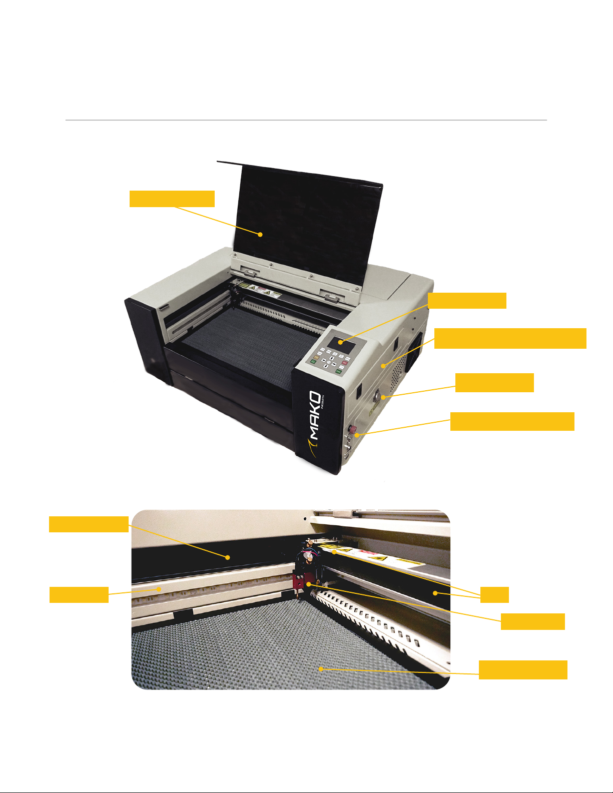
3.5 MAKO LASER DIAGRAM
14
Emergency Stop Button
Protective Cover
Control Panel
Optical Path Checking Panel
Water Cooler
Hex Cutting Bed
BeltGuide Rail
Gantry System
Laser Head

3.0 INITIAL SETUP
15
3.6 CONNECTING AIR FILTRATION TO AN STSTEM
Start by plugging in your Mako Laser Cutter into a suitable power outlet (as outlined in section 3.3
ELECTRICAL REQUIREMENTS).
Option 1 - Connect to the Mako Laser Cutter Air Filtration System
Follow the specic instructions included with your Mako Laser Cutter Air Filtration System to install it
on your laser machine. To access the instructions please click the link here.
Option 2 - Mako Laser Cutter Air Filtration System
Alternatively, you can connect your Mako Laser Cutter to your building’s existing HVAC system. To do
so, use the exible aluminum hose included with your Mako Laser Cutter, and pipe it into an existing
vent. We recommend securing the connection points with tin tape to ensure that no fumes escape.

4.0 OPERATION
4.1 POWERING ON
1. Before powering on the Mako Laser ensure that the protective cover is closed.
2. Verify the safety Emergency Stop is not engaged (if it is, rotate it clockwise until it extends to the non-
engaged position).
3. Flip the main power switch on the right side of the machine to the on position, if you are using a 80w
and 100w the main power switch will be the key slot on the right side.
Transferring Files to the Mako Laser Cutter
• Insert the USB stick into the lower port of the two USB ports on the back side of the Mako Laser
Cutter.
• On the control panel of the laser, press the “le” button. The les currently stored in the internal
memory in the laser will be displayed in a box with a series of smaller boxes to the right.
• Use the white arrow keys on the keypad to navigate over to the smaller boxes then navigate down
until you reach the box called “UDisk+”.
• Press the “Enter” button on the keypad. The display will refresh with an empty window on the left
and a new group of boxes on the right.
• Select “Read UDisk File”. The left window will populate with the names of all of the laser les stored
in the parent directory of the USB stick.
• Use the arrow keys to highlight the le you want to use.
• Use the left and right arrow keys to toggle back to the boxes on the right side of the screen.
• Navigate down to “Copy to Memory” and highlight it. Press the “Enter” button.
• Press the “ESC” button on the interface twice. This will exit the machine from le displaying mode.
• Press the “File” button once more.
• The le that was copied will now be displayed in the list of les in the box at the left of the display
screen. Use the curser to scroll up or down until the le that is needed is highlighted.
• Press the “Enter” button. The le is now in the active memory of the machine and is ready to run.
There are a limited number of le names which can be displayed on the screen at one time, so other
les in the laser cutter’s memory may only become visible when the curser keys are used to scroll up or
down through the list.
The menu option displayed on the screen will cycle from the bottom. It is not necessary to reverse
scrolling direction – the list will simply loop. Do not leave too many les loaded in the machine at one
time. It will slow the process of le selection and may completely ll the limited memory space of the
onboard computer. To delete les, select them in the left window then navigate in the right boxes to
highlight the “Delete” option. Then press Enter.
16

4.2 CALIBRATING THE MAKO LASER CUTTER
The gantry system is made up of the motors and linear rails that allow for the laser head to travel during
operation. It’s important to make sure that all body parts are out of the travel path of any moving parts.
Once the machine is powered on, use the direction keys on the keypad to move the laser head around.
It should do so relatively quietly, and at the same rate in all directions. If this is not the case, proceed to
Troubleshooting before moving on to the next steps.
4.0 OPERATION
17

4.0 OPERATION
Debugging the Light Path
The light path of the laser tube is calibrated during the manufacturing process, however it’s a good idea
to recalibrate the laser after transportation to ensure the safety performance of the machine.
The optical system of the laser cutter consists of a laser CO2 tube, three reection mirrors, 1 focus
lens, a laser head and red dot position system. Please refer to the diagram below.
Testing the Laser Tube
Ensure that the ow of water within the laser tube is in the high to low voltage direction. The water
will be owing from left to right you (from the end with the red connector to the end with the black
connector). You will be able some ow in the middle of the laser tube. Only look while the laser is not
being red.
The Mako Laser cutter works by shooting a beam of light from the laser tube, which is then reected
and by the rst, second, and third mirrors. After reecting off of the third mirror the light beam is shot
through the focus lens and reaches the work table.
It’s through the process of reecting and focusing that we’re able to achieve the best cutting and
engraving results. If the light path isn’t properly calibrated, it may damage the laser tube, reectors, lens
or result in poor cutting and engraving outcomes. Please calibrate the laser tube using the following
three steps:
18
CO2 Laser Tube
First Reection Mirror
Second Reection Mirror Third Reection Mirror
Focusing Lens
Laser Head
Red Dot
Position System

4.0 OPERATION
STEP ONE: Mirror 1 Adjustments
Open the machine lid and move the gantry system to the front of the machine. Use the Housing Keys to
open the side panel of the machine to access the laser mirrors. To align the reection of Mirror 1, place
a small amount on masking tape over the aperture of Mirror 2. With the cover and side panel closed,
use the pulse button on the control panel to send a beam of light from the laser. After a quick pulse,
open the lid and side panel to examine the location of the laser pulse on the tape of Mirror 2. Use the
knobs on Mirror 1 to make small adjustment as needed in order to align the laser beam according to the
diagram below.
STEP TWO: Mirror 2 Adjustments
To align the reection of Mirror 2, repeat the previous steps but place the masking tape on Mirror 3.
Adjust the knobs on Mirror 2 as necessary in order to align the laser beam according to the diagram
below.
19
Tape on Mirror 2 Adjust knobs on Mirror 1
Tape on Mirror 3 Adjust knobs on Mirror 2 Ideal laser beam location
Ideal laser beam location
Vertical Angle Adjuster
Horizontal Angle Adjuster

4.0 OPERATION
STEP THREE: Mirror 3 Adjustments
To align the reection of Mirror 3 you will again use the masking tape, but place it on the bottom of the
metal laser nozzle. Adjust the knobs on the top of the laser head accordingly to align with the diagram
pictured below.
It is important to ensure all three mirrors on the laser machine are adjusted accordingly in order to
ensure optimal machine performance and the life of the laser tube.
20
Tape on Laser Nozzle Adjust knobs
Ideal laser beam location
This manual suits for next models
2
Table of contents
Popular Cutter manuals by other brands


Makita
Makita BCS550 instruction manual

Clarke
Clarke CMB710 Operation & maintenance instructions

Fein
Fein SuperCut FSC 2.0-SC Parts Breakdown

Campbell Hausfeld
Campbell Hausfeld Air Cut-Off Tool operating instructions

MyBinding
MyBinding MBM BC12 instruction manual

TYROLIT Hydrostress
TYROLIT Hydrostress PPH25RR Series Operating instructions and spare parts list