Inncom B573 User manual

277 · West Main Street· Niantic, CT · USA · 860-739-4468 · www.inncom.com 1
B573 Ethernet Router and B573 Media Connector Software
TCT Router and FLN5 RS-485 Floor Bridge Applications
INNCOM’s B573 Ethernet Router
The B573 is configured by the software loaded into it at the factory to support 4 types of applications:
TCT Router (MBX) Application : Inncom related data (room temperature, occupancy, rental status, etc) to/from
the guestroom is sent through a TCT room gateway device located in each guestroom. The TCT is connected to
a network hub or switch inside the guestroom that is connected to the hotels “guest-side” (or public) network. A
single B573 connected to the “guest-side” (or public) network is programmed to rout Inncom data to and from all
of the TCT’s , and then make this data available to the Inncom software running on the Inncom server.
RS-485 FLN5 (Floor Level Network 5) Floor Bridge Application: Inncom related data (room temperature,
occupancy, rental status, etc) to/from the guestroom is sent via an RS-485 twisted pair wiring network connected
between the room gateway device (ie E528 thermostat, X529 , TCC, B485, etc) and the RS-485 Com ports on
the rear of the B573. This data is then made available to the Inncom software running on the Inncom server.
Room Gateway Application: Whereas the above mentioned TCT Router (MBX) and RS-485 FLN5 Floor Bridge
modes of the B573 are intended to rout data from all connected room gateway devices toward the Inncom Server
computer, the B573 itself can be programmed to act as an advanced room gateway device in installations
where guestrooms contain a tablet PC device. The specialized wireless communication protocols used by the
tablet PC device require a special B573 room gateway device to be installed. The B573 programmed as a Room
Gateway acts as an advanced TCT and bridges these specialized tablet PC protocols to a B573 TCT Router
(MBX), which in turn makes the information available to the Inncom Server.
FLN5 (Floor Level Network 5) Reflector Application: A B573 programmed as an “FLN5 Reflector” is used at
installations containing large, multi room suites that can not be adequately managed by the normal Inncom suite
linking functionality.
The TCT Router (MBX) and RS-485 FLN5 Floor Bridge applications are the most common. In both of these
applications, the B573 routs Inncom related messages from all connected room gateway devices to/from the
Inncom Server. The only difference being the type of physical network used to connect the room gateway device
to the B573. For the TCT MBX application, the hotels TCP/IP Ethernet network is utilized. For the RS-485
FLN5 application, a serial RS-485 twisted pair network is utilized. The TCT Router (MBX) and RS-485 FLN5
Floor Bridge applications will be covered in detail by this document.
The Room Gateway and FLN5 Reflector applications are much less commonly used and are not covered by this
document. Refer to Inncom application note “AN214 Suite Linking with Reflection” for details on the FLN5
Reflector mode, and Section 3.4 of the B573 Engineering manual for details on the B573 Room Gateway mode.
B573 User
Manual
Overview

B573 User Manual
Revision 1.2, Issued 5/15/08
277 · West Main Street· Niantic, CT · USA · 860-739-4468 · www.inncom.com 2
B573 MBX (TCT Router) Application
A single B573 configured as an "MBX" is used at a hotel that has a pre-existing TCP/IP Ethernet network
installed. An Inncom TCT "room Ethernet gateway" device is installed in each guestroom. The TCT
sends/receives Inncom related room information to and from the B573 MBX router over the “guestroom” (public)
Ethernet network.
Inncom related room information (ie temperature, control messages ,etc) sent/received between the TCT
“Room Gateway” and B573 MBX over the Guestroom Network using Layer-2 (MAC address based)
protocol via UDP Port 23210. TCT’s have NO IP address assigned. Only a unique MAC address
programmed at the factory.
“B573 Media Connector” software running on Inncom Server communicates with B573 MBX via UDP
Port 3008 to send/receive Inncom guestroom data. This link is typically routed through a Firewall
that must be configured to bi-directionally pass UDP Port 3008 traffic. If a firewall is present, it must
be configured to pass UDP Port 3008 data. The “B573 Media Connector” software also makes the
room data available to other software components running on the Inncom Server (ie WinP5PT).

B573 User Manual
Revision 1.2, Issued 5/15/08
277 · West Main Street· Niantic, CT · USA · 860-739-4468 · www.inncom.com 3
B573 FLN5 Floor Bridge Application
The B573 when configured as an FLN5 (Floor Level Network 5) Floor Bridge can maintain two RS485 twisted pair
communication links (A + B). Each RS485 link can support up to 50 "room gateway" device connections (ie TCC ,
E528, X529 , B485 or K592). The Inncom data from the "room gateway" device entering the B573 via the RS485
Com A or COM B ports is routed to the Ethernet network by the B573, where it is picked up by the "B573 Media
Connector" software running on the Inncom Server computer and made available to other Inncom software
running on the Inncom Server (ie Win P5PT) .
A B A B
Maximum 100 RS-485 connections per B573
(50 on COM_A , 50 on COM_B)

B573 User Manual
Revision 1.2, Issued 5/15/08
277 · West Main Street· Niantic, CT · USA · 860-739-4468 · www.inncom.com 4
Table of Contents:
Section 1: B573 Installation....................................................................................................................... 5
1.1 Mount the B573:.............................................................................................................................. 7
To Rack Mount the B573:................................................................................................................... 7
To Surface Mount (To a Wall) the B573:........................................................................................... 7
1.2 Connect Communication Wiring to the B573 ................................................................................. 8
1.3 Power the B573.............................................................................................................................. 11
IMPORTANT: Notes on Grounding the B573................................................................................ 12
1.4 Set the Network IP Address and Subnet Mask of the B573.......................................................... 13
“Ping” B573 IP Address From Inncom Server Computer................................................................ 14
1.5 Verify / Set the TCT Port Offset If Configuring a B573 MBX TCT Router................................. 15
1.6 Configure and Save B573 Media Connector Software Script File (B573_MC.cfg) ..................... 16
1.7 Configure and Save the WinP5PT.p5s script file to Support B573(s)........................................... 18
1.8 Start “WinP5PT.exe” and “B573_MC.exe” Programs and Verify Operation............................... 19
1.9 Verifying Room Communication ................................................................................................. 21
Section 2: Accessing and Using the B573 LCD Display Menu Screens................................................. 22
Front Panel Button Descriptions........................................................................................................... 22
Entering the B573 Main Menus............................................................................................................ 22
1. Server Menu..................................................................................................................................... 23
1.1 Trace Menu................................................................................................................................ 24
1.2 Function Menu........................................................................................................................... 26
2. Setup Menu...................................................................................................................................... 27
2.1 Network Menu............................................................................................................................ 28
2.2 Device Menu.............................................................................................................................. 29
2.3 FLN5 Test Pattern Menu ............................................................................................................ 30
3. Utility Menu.................................................................................................................................... 31
3.1 View IP Setup............................................................................................................................. 31
3.2 View Server Address .................................................................................................................. 31
3.3 Reset............................................................................................................................................ 31
3.4 View Errors................................................................................................................................. 31
B573 Troubleshooting .............................................................................................................................. 32
Technical Specifications........................................................................................................................... 38
B573 Front Panel Button and LED Descriptions...................................................................................... 39
References................................................................................................................................................. 40

B573 User Manual
Revision 1.2, Issued 5/15/08
277 · West Main Street· Niantic, CT · USA · 860-739-4468 · www.inncom.com 5
Section 1: B573 Installation
Read First:
The B573 is not a stand-alone device like its predecessor, the B572. For its intended operation as a bridge/router,
the B573 hardware relies on being “connected” to a software program called the “B573_MC.exe” (B573 Media
Connector) that must always be running on the Inncom server computer:
The B573 is “dumb” without being connected to the “B573_MC.exe” software, and only provides the ability to
locally configure its network IP address and Subnet, reset itself and a perform a few other troubleshooting
functions.
The “B573_MC.exe” software connects to the B573 using the IP address and Subnet defined in the
“B573_MC.cfg” script file that must be present in the “C:\Inncom\Scripts” folder on the Inncom server. This script
file defines the IP address(s) of any B573(s) physically installed. When the “B573_MC.exe” program first starts
up, it scans the network for the defined B573 IP addresses defined in the “B573_MC.cfg” script file. Once the
“B573_MC.exe” program connects to the defined B573(s), the room data passing through the B573(s) now
becomes available to other software running on the Inncom server, specifically the “WinP5PT.exe” program.
The “WinP5PT.exe” software on the Inncom server handles gathering and routing “process images” to/from
rooms via the above mentioned “B573_MC.exe” program. WinP5PT.exe then makes this room information
available to other software components running on the Inncom server, such as Netcom.exe, WSCon.exe
(Workstation Concentrator) and DCenter.exe (Data Center).
Single B573 “MBX”
Configured for TCT’s
Application
Multiple B573’s
Configured for “FLN5”
RS-485 Floor Bridge
Application

B573 User Manual
Revision 1.2, Issued 5/15/08
277 · West Main Street· Niantic, CT · USA · 860-739-4468 · www.inncom.com 6
Installation Considerations:
1. Determine the mounting location for the B573(s) using the following considerations:
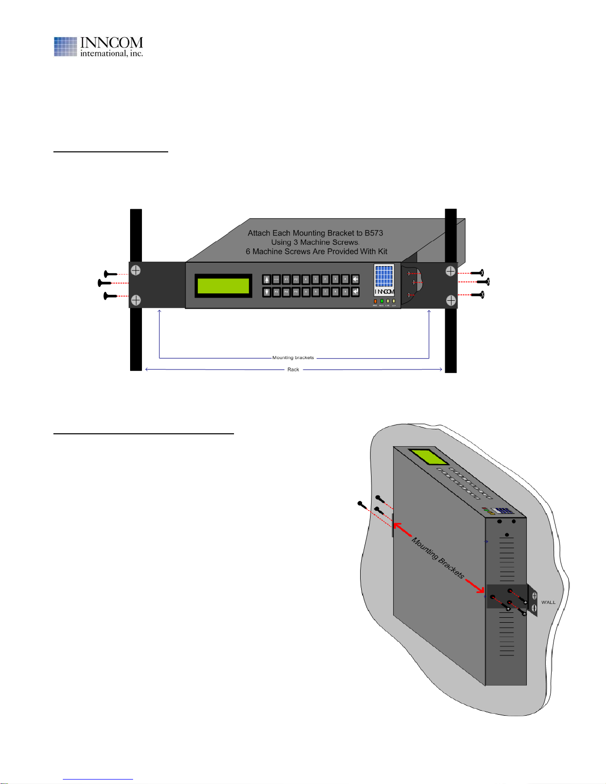
•The B573 is designed for a 1U, 19” wide rack mount installation using the brackets and bracket
mounting screws provided, but it can also be placed on a flat surface or mounted vertically on a wall.
•It should be installed so that the front panel LCD display and buttons are easily accessible.
•The mounting location should have a 100-240VAC , 1 Amp minimum power source in the vicinity of the
B573 mounting location. If the B573 has the optional 01-9981.A1 100-240VAC power supply installed, a
6 foot AC line cord is provided.
•The B573 consumes about 4 watts (300mA @ 12VDC) when powered, therefore it does not require any
forced ventilation. But, it should be mounted in a location where the ambient temperature is 50-104 F (10-
40 C).
•The B573 communicates with the Inncom Server computer via a network connection. Therefore the B573
location must provide a connection to the same network that the Inncom Server is connected to.
2. Network connectivity considerations:
•The B573 requires a fixed (static) network IP Address. This is programmed into the B573 using the front
panel LCD display and buttons. The B573 DOES NOT support DHCP. You must coordinate with the
hotels IT department to obtain a fixed IP address for each installed B573 and program it into the B573.
•The Inncom “B573_MC.exe” program running on the Inncom Server must know the IP addresses of all
B573’s in order to connect to them. The B573 IP addresses must manually be defined in the
“B573_MC.cfg” script file located in the “C:\Inncom\Scripts” folder on the Inncom Server. If any B573 IP
address is changed, the “B573_MC.cfg” script file must be updated to match and the “B573_MC.exe”
program restarted.
•The B573 communicates with the “B573_MC.exe” program running on the Inncom Server via network
UDP Port 3008. If a network Firewall is installed to separate the network that the B573 connects to and
the network that the Inncom Server connects to, the Firewall must be configured to bi-directionally pass
UDP Port 3008 traffic. This situation is typical for an installation using a B573 “MBX” with TCT room
gateway devices installed. The B573 MBX and all TCTs are connected to the guestroom (public) network,
and the Inncom Server is connected to the hotels administrative (private) network.
•If Inncom TCT “room gateway” devices are installed, the TCT’s communicate with the installed B573
MBX router via network UDP Port 23210. This Port must be open and available on the network
connecting all TCT’s to the B573 MBX, which it typically is open by default.
3. Room device connectivity considerations:
•The B573 configured as an “MBX TCT Router” can support virtually an unlimited number of TCT room
gateway connections.
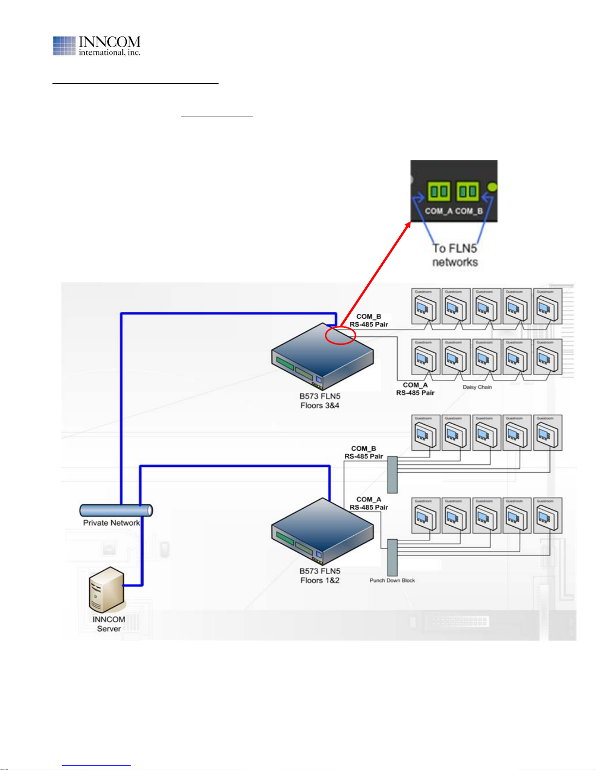
However, the B573 configured as an “FLN5 RS-485 Floor Bridge” can only support a maximum of 100
room gateway connections (50 on COM_A, 50 on COM_B). This limitation must be considered when
deciding what rooms connect to what B573 FLN5 RS-485 bridge. Note that “room gateway connection”
refers to the termination of the RS-485 wiring pair at a particular Inncom device (ie E528, B485,
X529,etc). For instance, if a hotel has an E528 and a K592 Lock Gateway installed in each room, this
counts as 2 RS-485 terminations and you would be limited to 50 total “room” connections (100 total
devices).
Typical B573 Installation Steps:
1. Install the B573 hardware.
2. Connect communication wiring to the B573.
3. Apply power to the B573.
4. Obtain and set the IP Address and Subnet into the B573.
5. Set/verify the “TCTPort Offset” in the B573 MBX (only if property has a single B573 MBX with TCTs).
6. Configure and save the “B573_MC.cfg” script file to contain the IP addresses of all B573(s).
7. Configure and save the “WinP5PT.p5s” script file to tell WinP5PT it will “locally” connect to the
“B573_MC.exe” program (they both run on the same Inncom Server computer).
8. Start (or Re-Start) “B573_MC.exe” and “WinP5PT.exe” programs and verify operation.

B573 User Manual
Revision 1.2, Issued 5/15/08
277 · West Main Street· Niantic, CT · USA · 860-739-4468 · www.inncom.com 7
1.1 Mount the B573:
The B573 is packaged in a 1U rack mount configuration, designed for a 19" server rack. It is shipped with 2
removable mounting brackets and 6 machine screws to attach the brackets to the B573 body. The brackets
enable the installer to rack-mount or wall-mount the B573. Figure 1 shows rack-mounting the B573 and Figure 2
shows a wall-mounting the B573.
To Rack Mount the B573:
•Attach the mounting brackets to the B573 body using the provided machine screws as shown in Figure 1.
Three tapped holes are on the left and right sides of the B573 near the front of the B573 to accept the
machine screws.
•Insert the B573 into the Rack and attach using the mounting screws/bolts provided with the rack.
To Surface Mount (To a Wall) the B573:
•Attach the mounting brackets to the sides of the B573 body
using the provided machine screws as shown in Figure 2.
Three tapped holes are on the left and right sides of the B573
near the middle to accept the machine screws to attach the
mounting brackets to the B573.
•Mount the B573 to the wall/surface using appropriate anchors
and screws.
Figure 1. B573 Rack-Mounted, Front View
Figure 2. B573 Wall-Mounted, Side View

B573 User Manual
Revision 1.2, Issued 5/15/08
277 · West Main Street· Niantic, CT · USA · 860-739-4468 · www.inncom.com 8
1.2 Connect Communication Wiring to the B573
For B573 MBX (TCT Router) Installation:
When the B573 is configured as a TCT router (MBX), the only communication wiring to connect is the CAT5
Ethernet patch cable that connects the B573 to the same network that has all the TCT’s attached.
Connect the network patch cable from the switch or hub that places the B573 on the TCT network to the RJ45
network jack (labeled I/O Base) on the rear of the B573

B573 User Manual
Revision 1.2, Issued 5/15/08
277 · West Main Street· Niantic, CT · USA · 860-739-4468 · www.inncom.com 9
For B573 FLN5 RS-485 Twisted Pair Floor Bridge Installation:
1. Connect the B573 COM_A and COM_B terminals to the RS-485 twisted pair wiring going out to the
appropriate room punch block(s) (“home run” wiring scheme) or room “daisy chain” wiring using the
removable 2-pin green terminal blocks provided with the B573. Read the notes on page 10.
2. Connect the network patch cable from the switch or hub that places the B573 on the same network as the
Inncom server to the RJ45 network jack (labeled I/O Base) on the rear of the B573.
B573 FLN5 RS-485 Communication Wiring Examples
Note: The sample wiring diagram below is meant to show only the general FLN5 RS-485 communication
related wiring. This example shows a “home run” type wiring scheme where the RS-485 pair from each room
terminates at a punch-down block. A “daisy-chain” scheme can also be utilized. Power and other signals that
may also be present in the cabling are not shown. Refer to the specific device documentation for details.

B573 User Manual
Revision 1.2, Issued 5/15/08
277 · West Main Street· Niantic, CT · USA · 860-739-4468 · www.inncom.com 10
IMPORTANT:
•Each B573 FLN5 COM Port (COM_A and COM_B) can typically support up to 50 RS-485 “room gateway
device” connections. Therefore 100 total connections per B573. These “room gateway devices” include:
01-9560 E528 Thermostat
TCC
B485
X485
K592C
•The FLN5 RS-485 twisted pair wiring is polarity sensitive. The two wires that make up the pair are
referred to as the “A” wire and the “B” wire. You must maintain consistency when connecting the RS-485
wiring pair as shown in the image on page 9 (ie A to A and B to B in all of the terminations).
•The wiring used for the RS-485 wiring should be twisted pair cable such as CAT5 or similar. Typical
wiring used is 22-24 AWG STP but this will depend on the length of the cable runs. The specified
maximum cable lengths for RS-485 is 4000 feet, but this may be shorter depending on quality and type of
twisted pair wiring used and the number of devices connected.
•Before making any actual termination between the RS-485 pair coming from a particular room and the
B573 COM port , verify the pair has no shorts or excessive voltage present that may indicate the wiring
pair has a problem that could damage the B573 when connected.
A Fluke meter (or similar) should be used to check the RS-485 pair from a particular room before
connecting it to the punch down block or “daisy chain” wiring connected between rooms. This check
should include measuring the resistance across “A” and “B” to verify a dead short does not exist and
measuring both AC and DC voltages across the RS-485 pair (“A” wire to “B” wire) AND from the “A” wire
to Earth ground and the “B” wire to Earth ground.
Typical Expected Values:
Resistance “A” to “B” : Greater than 1Mega Ohm (meter may indicate “open”)
AC Voltages: With meter set to measure AC voltage, there should be NO discernible AC voltage from A
to B, Ato Ground or Bto Ground. Any AC voltage > 100-200 mV AC is suspect and should be
investigated.
DC Voltages: With meter set to measure DC voltage the following typical voltages are expected with the
RS-485 wiring pair connected to the Room Gateway device ONLY (ie the device has not been connected
to any other room wiring pairs at the punch down/daisy chain or has not been connected to the B573
COM port).
Room Gateway Device “A” to “B” “A” to Ground “B” to Ground
01-9560 E528 Thermostat 3.8 VDC 4.2 VDC 0.4 VDC
TCC 0.28 VDC 0.32 VDC 0.04 VDC
B485 1.0 VDC 1.0 VDC 0.0 VDC
X485 3.8 VDC 4.2 VDC 0.4 VDC
K592C 1.0 VDC 1.0 VDC 0.0 VDC

B573 User Manual
Revision 1.2, Issued 5/15/08
277 · West Main Street· Niantic, CT · USA · 860-739-4468 · www.inncom.com 11
1.3 Power the B573
The B573 can be powered using one of the three options shown below. Please read the note on grounding the
B573 that follows the power option descriptions.
Power Option 1: B573 receives power from 12VDC power connected to the 12VDC Power jack (red circle shown
below). A 2.1mm, center pin positive DC power jack is provided at the lower right on the back of the B573 to
connect a 12VDC power supply. The 12VDC power supply used must supply at a minimum 300mA to power this
single B573. A 120VAC to dual 12VDC output power supply (Inncom P/N 04-4040) is available that can power 2
B573’s.
Power Option 2: B573 receives power via COM_D1/COM_D2 "Daisy Chain" (green circles shown below).
If installing multiple B573's in the same location, it is possible to "daisy chain" 12VDC power from one B573 (the
one connected to the 12VDC power supply or 120VAC) to additional B573's.
Note 1: If powering additional B573's via the 12VDC power daisy chain connectors COM_D1/D2, the 12VDC
power supply must be sized to provide at least 300mA per B573 (including the B573 connected to the 12VDC
power supply). For example, a minimum 900mA 12V power supply would be required to power 3 B573s.
Power Option 3: B573 has optional 100/240 VAC power supply installed (dotted yellow section in image below).
This power supply is rated at 1A DC.
Plug the AC line cord provided with the B573 into the “AC IN” socket as shown below.

B573 User Manual
Revision 1.2, Issued 5/15/08
277 · West Main Street· Niantic, CT · USA · 860-739-4468 · www.inncom.com 12
When you first apply power to the B573, the following information will appear on the B573 LCD display:
1. First, the network MAC address programmed into the B573 will
appear for a few seconds. This is programmed at the factory.
2. Next, the Network IP Address and Subnet programmed into the
B573 will appear for a few seconds. The IP Address and Subnet can
easily be changed using the LCD display and buttons on the front of
the B573. This is covered in Section 1.4 on page 13.
3. Then, the B573 type and software version of the B573 will appear:
B573 is programmed as an “MBX” TCT router and its software
version is Version 1.6.
B573 is programmed as an “FLN5 Gateway” (Floor Bridge with 2
RS-485 channels) and its software version is Version 1.10.
At this point, the B573 LCD display will remain displaying the B573 type and software version as shown in Step 3
above and the GREEN “DIAG” LED on the lower right of the B573 front panel will flash once/second UNTIL :
•The desired IP Address and Subnet values are set into the B573 using the B573 LCD and front panel
buttons. This will be covered in Section 1.4 on page 13.
•The “B573_MC.cfg” script file is created (or modified if it already exists ) to include the IP Address(s) of
any B573(s). This will be covered in Section 1.6 on page 16.
•The “B573_MC.exe” (B573 Media Connector Software) is running and has connected to the B573(s).
When the “B573_MC.exe” program connects to the B573, the GREEN “DIAG” LED will begin to flash
twice / second. This will be covered Section 1.8 on page 19.
IMPORTANT: Notes on Grounding the B573
For communication reliability and equipment protection, the B573 must be connected to earth ground.
If the B573 has the optional 120/240VAC power supply installed, the AC power source that you connect the AC
line cord from the B573 to must have a valid earth ground connection. The ground pin on the “AC In” socket on
the rear of the B573 is physically connected to the B573 metal housing and to any “common” pins on any of the
connectors on the B573.
If powering the B573 with a 120/240 VAC to 12VDC power supply via the “DC Power” input jack on the bottom left
rear of the B573 , the power supply should internally bond its 12VDC Common output to the 120/240 VAC input
Earth ground connection. Any 120/240 VAC to 12VDC power supplies provided by Inncom (including P/N 04-
4040) will have the 12V DC output common internally connected to the Earth connection.
If using a 12VDC power supply that does NOT internally bond the 12VDC common to earth,
there is a marked Earth ground connection screw and lug on the upper left on the back of the
B573 that can be used to physically connect the B573 chassis to Earth ground.

B573 User Manual
Revision 1.2, Issued 5/15/08
277 · West Main Street· Niantic, CT · USA · 860-739-4468 · www.inncom.com 13
1.4 Set the Network IP Address and Subnet Mask of the B573
The B573 does not support DHCP dynamic addressing and requires a static IP Address be programmed into it
using the B573 front panel buttons and display. . You may need to consult with the properties IT department to
obtain the IP address and Subnet to be set into the B573. If installing multiple B573's, you will need a unique
IP address for each B573. If the Subnet has not been provided to you, this is typically set to 255.255.255.0.
The B573 “2. Setup” menu is used to change the IP address and Subnet. Accessing the Setup menu requires a
password of 61959 as shown below.
Set the IP address in the B573 using the following steps :
Set the Subnet Mask in the B573 using the following steps:

B573 User Manual
Revision 1.2, Issued 5/15/08
277 · West Main Street· Niantic, CT · USA · 860-739-4468 · www.inncom.com 14
“Ping” B573 IP Address From Inncom Server Computer
With the correct IP address and Subnet programmed into the B573(s) and the B573(s) powered and connected to
the network, “Ping” the B573 IP address from the Inncom Server computer to verify network communication.
On the Inncom Server:
a. Open a DOS “Command Prompt” by selecting “Start>Run” and entering “cmd” in the input field, then click “OK”
b. Enter “ping xxx.xxx.xxx.xxx” where “xxx.xxx.xxx.xxx” is the IP address of the B573 into the DOS
window and press the Enter key.
c. If the B573 with the defined IP address replies, you will see 4 replies appear in the DOS window , here an
audible “click” from the B573 and see the IP Address of the “pinging” computer on the B573 display (see note
below) for each of the 4 replies.
This example shows “pinging” an the B573 with IP Address of “168.1.5.85” from a computer with IP Address
“168.1.1.87” and getting replies from the B573 with that IP Address.
Note: If the B573 is configured to do so , the B573 will emit an audible “click” and display the IP Address of
the computer “pinging” the B573 (see image below) when it receives a network “ping”. This feature is
enabled by default but can be disabled from B573 front panel. If you do not here an audible “click” or see the
pinging computers IP Address on the LCD display, it is possible that this has been disabled in the B573.
B573 menu item “2.2.2 Show Ping” is used to configure this feature and is covered on page 26.
d. If the B573 does not reply to the Ping, verify the IP Address you are “pinging” is matches the IP
Address programmed into the B573. Is the intended B573 powered and connected to the same
network as the Inncom Server? Was the Subnet programmed into the B573 correctly?

B573 User Manual
Revision 1.2, Issued 5/15/08
277 · West Main Street· Niantic, CT · USA · 860-739-4468 · www.inncom.com 15
1.5 Verify / Set the TCT Port Offset If Configuring a B573 MBX TCT Router
If a B573 is installed at a property that uses TCT room gateway devices, the TCT devices are supposed to
communicate with the B573 over the Ethernet network using a default “TCT Port” value of “23210”. 23210 is the
TCP/IP network port# that the B573 and the TCT’s communicate over.
The B573 MBX supports changing this TCT Port value by adding an offset value to the baseline value of 23210.
This is done to allow more than one B573 MBX to be used on the same network. However using more than one
B573 MBX is only done under special rare circumstances. This “TCT Port Offset” value stored in the B573 MBX
should ALWAYS be set to “0”, which then sets the actual TCT Port to 23210 (ie baseline 23210 + offset 0 =
23210) . The “TCT Port Offset” value is stored in the “non-volatile” memory ( NVRAM) of the B573 MBX at
NVRAM Offset “16”.
Use the following steps to verify the B573 TCT Port Offset value is set to “0”. This procedure leads you through
entering the B573 “manufacturing” menu, then selecting NVRAM offset 16 to view the current TCT Port Offset
value.

B573 User Manual
Revision 1.2, Issued 5/15/08
277 · West Main Street· Niantic, CT · USA · 860-739-4468 · www.inncom.com 16
1.6 Configure and Save B573 Media Connector Software Script File (B573_MC.cfg)
The "B573_MC.cfg" file is a text file that must be present in the "C\Inncom\Scripts" folder on the Inncom server
computer. This file tells the "B573 Media Connector" software (B573_MC.exe) running on the Inncom server the
IP addresses of any B573 devices installed. The “B573_MC.exe” program scans this file on startup for any line
that begins with “$B573:” without a semi-colon (;) in front and begins searching for the B573(s) with the defined
IP address.
** Any B573 installed must have a line item in the “B573_MC.cfg” script file defining its IP address **
The exact format of this line item is:
If using a SINGLE B573 MBX configured to support TCTs:
An installation with TCT room gateway devices installed will have only one B573 installed. The “B573_MC.cfg”
script file should only define ONE B573 IP address. The single active line (doesn’t start with a semicolon) in the
“B573_MC.cfg” script file should have the following format to define the IP address of the single MBX B573:
$B573: IP: xxx.xxx.xxx.xxx Port: 3008 Name: "Descriptive Name" Rooms: yyy
If using one or more B573(s) configured for an FLN5 RS485 twisted pair network:
A line with the following format must be placed in the "B573_MC.cfg" file for EACH B573 configure for FLN5
RS485 mode:
$B573: IP: xxx.xxx.xxx.xxx Port: 3008 Name: "Descriptive Name" Rooms: yyy FLN5: Y
•xxx.xxx.xxx.xxx is the network IP Address of the particular B573.
•Port: 3008 is the network port that the B573 communicates over to reach the “B573_MC.exe” program. DO
NOT CHANGE this value. It must be 3008.
•The text placed into the "Descriptive Name" field appears on the top line of the B573 LCD display when the
B573 Media Connector software is running and has successfully connected to the B573.
•The number of rooms defined by "yyy" in the B573_MC.cfg script file tells the WinP5PT program running on
the Inncom Server how many rooms are supposed to be communicating through that particular B573. The
actualnumber of rooms communicating through a particular B573 are displayed on the bottom line of the
B573 LCD display once the B573 has connected to the “B573_MC.exe” program. If the # rooms is not
known, set the "Rooms: yyy" field to "0" (Rooms: 0).
•If the B573 is configured for an FLN5 RS-485 twisted pair network, the line MUST end with “FLN5: Y”
A default "B573_MC.cfg" file similar to the one below will typically be present in the "C\Inncom\Scripts" folder
on a new server computer to show the required format. This default file has 2 example B573 line items showing
the format needed to connect the “B573_MC.exe” program to either a B573 MBX TCT router or a B573 FLN5
Floor Bridge. You must open and edit this file using Windows “Notepad” or “Wordpad” text editor to include
the actual IP address(s) of any B573(s). Notice both of these B573 lines are commented out (leading semi-colon).
If this file is not present in the "C\Inncom\Scripts" folder , you must create it using Notepad or Wordpad and save
it to the "C\Inncom\Scripts" folder with the exact name of “B573_MC.cfg”.
Default B573_MC.cfg file that will typically be present in the "C\Inncom\Scripts" folder:
; Test script file for B573 Media Connector
; One line per B573 connected.
; If using TCTs as room gateways, there will be only one connection.
; If using FLN5 room gateways, the FLN5 tag must be set in each line.
; If the number of rooms is not known, leave at 0. If set, B573 will display "x rooms of y", quickly showing
; how many non-communicating rooms are on that bridge.
;$B573: IP:10.101.112.255 Port: 3008 Name:"FLN5 Test" Rooms: 0 FLN5: Y
;$B573: IP:192.168.254.88 Port: 3008 Name:"TCT Test" Rooms: 0

B573 User Manual
Revision 1.2, Issued 5/15/08
277 · West Main Street· Niantic, CT · USA · 860-739-4468 · www.inncom.com 17
Example B573_MC.cfg script files:
; B573_MC.cfg script file for single B573 MBX with TCTs installed
; Park Plaza MBX will be displayed as the B573 description on the LCD display
; 425 actual rooms exist
$B573: IP:168.1.5.60 Port: 3008 Name: "Park Plaza MBX" Rooms: 425
; B573_MC.cfg script file for 3 B573 FLN5 Floor Bridges
; One line per B573 connected.
; The FLN5: Y tag MUST be at the end of each line.
; Atlantis Floor 6,7,8 displayed as B573 descriptions
; 75,63 and 80 actual rooms are scripted
$B573: IP:168.1.5.85 Port: 3008 Name: "Atlantis Floor 6" Rooms: 75 FLN5: Y
$B573: IP:168.1.5.86 Port: 3008 Name: "Atlantis Floor 7" Rooms: 63 FLN5: Y
$B573: IP:168.1.5.87 Port: 3008 Name: "Atlantis Floor 8" Rooms: 80 FLN5: Y
IMPORTANT:
•Once you create or modify the "B573_MC.cfg" script file, you must save it to the "C:\Inncom\Scripts" folder
on the Inncom server computer, and then restart the "B573_MC.exe" program (see note below) on the
Inncom server for the changes to take affect.
Note: Before manually shutting down the “B573_MC.exe” program, check to see if the “Watchdog”
program has been installed on the computer and configured to restart the “B573_MC.exe” program in case it
is closed. If that is the case, used “Watchdog” to restart the “B573_MC.exe” program.
•If the IP address of any B573 changes, the "B573_MC.cfg" script file must be updated with the new IP
address and saved. The "B573_MC.exe" program must then be re-started for the change to take effect.
•Make sure the port defined in any “$B573: ……” line is “Port: 3008.
B573 display with above B573_MC.cfg script file once the
B573_MC.exe program has connected with the B573 with
IP address 168.1.5.60 and 400 rooms communicating
B573 with IP 168.1.5.85 display with above B573_MC.cfg
script file once the B573_MC.exe program has connected
with the B573 and 75 rooms communicating

B573 User Manual
Revision 1.2, Issued 5/15/08
277 · West Main Street· Niantic, CT · USA · 860-739-4468 · www.inncom.com 18
1.7 Configure and Save the WinP5PT.p5s script file to Support B573(s)
The “WinP5PT.exe” program must be told how to establish a link with the “B573_MC.exe” (B573 Media
Connector) program. Add (or verify it is already there) the following line to the “WinP5PT.p5s” script file to do
this:
$Media: B573 IP:localhost Port: 7002
The section in the WinP5PT.p5s script file where this line belongs immediately follows the commented section
that explains Media Connections as shown below:
;******************************************************
; There can be any number of Media Connection lines for
; the B572s or other devices connecting P5PT to the rooms.
; The Media: “IP: and “Port: are required fields.
; The "IP:" field is the address assigned to each device.
; One line in the script file is required for each media
; connection. The same format is used for the B572/MBX
;******************************************************
$Media: B573 IP: localhost Port: 7002
IMPORTANT: Notice that no actual IP address for a B573 is defined in the “WinP5PT.p5s” script file. The
“WinP5PT.exe” program does not connect to the physical B573 hardware. The “WinP5PT.exe” program
connects to the “B573_MC.exe” program, which actually connects to the physical B573(s). Since both programs
run locally on the same computer , “localhost” is entered as the IP address.
Depending on the particular setup at the property, there may be one or more existing “$Media: …..” lines in the
WinP5PT.p5s script file.
a. If the property was using an older B572 MBX to support TCT’s and you are replacing it with a new B573 MBX,
there will be a pre-existiing line in the Media section of the WinP5PT.p5s script file that defined the IP
address of the existing B572 MBX similar to:
$Media: B572 IP: XXX.XXX.XXX Port: 7002 (XXX.XXX.XXX is IP address of existing B572)
This line should be removed and replaced with “$Media: B573 IP: localhost Port: 7002” as shown above.
b. If keeping the existing B572(s) and adding an additional B573 (or B573’s), leave any existing “$Media: B572
IP: XXX.XXX.XXX Port: 7002 “ lines and add a SINGLE “$Media: B573 IP: localhost Port: 7002”
line to establish the link to the “B573_MC.exe” program.
For example:
; Media connection section with 2 B572 IP addresses defined and a SINGLE line item
; for the B573 to define WinP5PT.exe and B573_MC.exe link locally
;******************************************************************
$Media: B573 IP: localhost Port: 7002
$Media: B572 IP: 168.1.5.41 Port: 7002
$Media: B572 IP: 168.1.5.40 Port: 7002
IMPORTANT:
•Once you modify the "WinP5PT.p5s" script file, you must save it to the "C:\Inncom\Scripts" folder on the
Inncom server computer, and then shutdown and restart the “WinP5PT.exe” program (see note below) on the
Inncom server for the changes to take effect.
Note: Before manually shutting down the “WinP5PT.exe” program, check to see if the “Watchdog” program
has been installed on the computer and configured to restart the “WinP5PT.exe” program in case it is closed.
If that is the case, use “Watchdog” to restart the “WinP5PT.exe” program.
•Make sure the network port defined in the “$Media: B573 IP: localhost Port: 7002” line is in fact set to
“7002”.

B573 User Manual
Revision 1.2, Issued 5/15/08
277 · West Main Street· Niantic, CT · USA · 860-739-4468 · www.inncom.com 19
1.8 Start “WinP5PT.exe” and “B573_MC.exe” Programs and Verify Operation
With the “WinP5PT.p5s” script file modified to include the “$Media: B573 IP: localhost Port: 7002” line and
the “B573_MC.cfg” script file modified to include the IP Addresses of all B573’s, start or restart the
“WinP5PT.exe” and “B573_MC.exe” programs to ensure any changes take effect.
a. When the B573 Media Connector (B573_MC.exe) program first starts, the following window will appear:
P5PT Connection: will initially indicate “Listening” because the
“B573 Media Connector” program is waiting (listening) for the
“WinP5PT.exe” program to connect.
B573 List: window section will display a list of the scripted B573
IP Addresses (ie B573 IP Addresses defined in the
“B573_MC.cfg” script file configured in Section 1.6).
Until the “B573_MC.exe” program connects to a particular
scripted B573, the “Status” will indicate “Not Connected” and
“Rooms” will indicate “0” .
b. When the “B573_MC.exe” program connects to one of the scripted B573’’s:
The “Status” for the particular B573 will indicate “Connected” and
the number of room gateway devices (ie the room device
connected to the communication network) currently connected to
that particular B573 will be displayed in the B573Media Connector
window. This number will increase as additional rooms connect.
Also, the LCD display on the actual B573 that has become
connected to the “B573_MC.exe” program will change from
displaying the B573 type and software version to displaying:
•The name scripted in the “B573_MC.cfg” script file for the
particular B573 IP address that has become connected.
•The number of room gateway devices currently connected to
the particular B573.
•The current Windows system time of the Inncom server.
If after 1-2 minutes the “Status” for a defined B573 remains “Not Connected” and the LCD display on the
particular B573 has not changed to the “connected” screen, verify the following:
•Verify the scripted IP address in the ”B573_MC.cfg” script file for the B573 matches the IP address
actually programmed into the particular B573. If you modify the ”B573_MC.cfg” script file you must restart
the “B573_MC.exe” program (see note below). If the scripted IP address is correct, verify the IP address
programmed in to the particular B573 is correct and change to match the IP address scripted in the
“B573_MC.cfg” file.
Note: Before manually shutting down the “B573_MC.exe” program, check to see if the “Watchdog”
program has been installed on the computer and configured to restart the “B573_MC.exe” program in
case it is closed. If that is the case, used “Watchdog” to restart the “B573_MC.exe” program.

B573 User Manual
Revision 1.2, Issued 5/15/08
277 · West Main Street· Niantic, CT · USA · 860-739-4468 · www.inncom.com 20
•Verify the particular B573 is configured as an FLN5 RS-485 bridge. Verify the line item for the particular
B573 in the “B573_MC.cfg” script file has “FLN5: Y” at the end of the line.
•Verify the particular B573 is actually powered and connected to the network.
•Verify the TCP/IP network Port “3008” that the “B573_MC.exe” program and the B573’s communicate
over is not being blocked by a Firewall. Port 3008 must be open (which it typically is) to allow bi-
directional traffic.
c. When the “B573_MC.exe” program connects to the
“WinP5PT.exe” program (which can typically take 1-2
minutes), the “P5PT Connection” status will indicate
“Connected”
At this point, you can start the Inncom “Netcom.exe”,
“DCenter.exe” (Data Center) and “WSCon.exe”
(Workstation Concentrator) programs if not already
running.
Also start the InnControl graphical user interface software
and verify rooms begin to appear as communicating. You
will need set the 5 digit “Room ID” in the room “gateway”
device in each room if not already done.
If after several minutes pass after starting the “B573_MC.exe” program and the “P5PT Connection” status
remains “Listening” because the “B573_MC.exe” program has not connected to the “WinP5PT.exe” program,
verify the following:
Important:
•Verify the “WinP5PT.exe” program is actually running on the Inncom server. Start it if it is not running.
•Verify the “WinP5PT.p5s” script file located in the “C:\Inncom\Scripts” folder contains the
“$Media: B573 IP:localhost Port: 7002” line as discussed on page 16. The network port defined
MUST be “7002” as shown. . If you modify the “WinP5PT.p5s” script file to correct a problem with this line,
you must save the “WinP5PT.p5s” script file and restart the “WinP5PT.exe” program.
•Verify the network “port” 7002 that the “WinP5PT.exe” program and the “B573_MC.exe” program
communicate over is not being blocked by the Windows XP Service Pack 2 built-in Firewall. Port 7002
must be open (which it typically is) to allow bi-directional traffic between the “B572_MC.exe” and
“WinP5PT.exe” programs.
Table of contents