INNO Instrument View 900 User manual

Revision 1.0

View900 Cable Antenna Analyzer User Manual
INNO Instrument Inc.
Page 1 of 69
Table of Contents
SAFETY INSTRUCTIONS ................................................................................................................... 4
Strorage.....................................................................................................................................................5
Warning.....................................................................................................................................................5
CERTIFICATION................................................................................................................................ 6
1. General Information................................................................................................................ 7
1.1. DESCRPTION ...................................................................................................................................8
Key Measurements .................................................................................................................8
Key Measurements .................................................................................................................8
1.2. THE LAYOUT OF View900 ...............................................................................................................9
2. Instrument Overview............................................................................................................. 10
2.1. Front Panel ...................................................................................................................................11
Power Key..............................................................................................................................12
Mode Key ..............................................................................................................................12
ESC Key..................................................................................................................................12
Multi-function Button ...........................................................................................................12
Navigation Button .................................................................................................................13
Rotary Knob...........................................................................................................................13
Indicator ................................................................................................................................13
Display...................................................................................................................................14
DC Power Connector.............................................................................................................14
RF Out Port ........................................................................................................................14
Ethernet Port ->.................................................................................................................14
USB Port.............................................................................................................................14
2.2. Power Adaptor .............................................................................................................................14
2.3. Battery..........................................................................................................................................14
Installing a battery.................................................................................................................15

View900 Cable Antenna Analyzer User Manual
INNO Instrument Inc.
Page 2 of 69
Charging a Battery.................................................................................................................15
LOW Bttery............................................................................................................................16
Automatic Power Off when Battery Low ..............................................................................16
Caution..................................................................................................................................16
3. Menu Decriptions .................................................................................................................. 18
3.1. Menu Descriptions .......................................................................................................................19
Cable and Antenna Analyzer mode.......................................................................................20
Calibration.............................................................................................................................22
Setting ...................................................................................................................................23
Power Sensor ........................................................................................................................26
Files .......................................................................................................................................27
Information ...........................................................................................................................29
4. CSS Measure Descriptions..................................................................................................... 30
4.1. Tap Menu......................................................................................................................................31
Measure ................................................................................................................................31
FREQ......................................................................................................................................32
AMP.......................................................................................................................................33
Sweep....................................................................................................................................34
Marker...................................................................................................................................34
4.2. Multi-Function Button..................................................................................................................35
Cal-Numeric ‘1’......................................................................................................................35
Freq/dist-Numeric ‘2’............................................................................................................40
Autoscale-Numeric ‘3’...........................................................................................................42
Peak-Numeric ‘4’...................................................................................................................43
Trace-Numeric ‘5’..................................................................................................................43
Run/Hold-Numeric ‘6’ ...........................................................................................................45
Save-Numeric ‘7’ ...................................................................................................................45
Load-Numeric ‘8’...................................................................................................................46
Limit-Numeric ‘9’...................................................................................................................47
Preset-Numeric ‘’.............................................................................................................48

View900 Cable Antenna Analyzer User Manual
INNO Instrument Inc.
Page 3 of 69
.................................................................................................................................................48
Meas-Numeric ‘0’................................................................................................................................48
System-Numeric ‘+/-‘.........................................................................................................48
5. Tap Menu & Multi Function Button Descriptions ................................................................. 52
5.1. VSWR-VSWR Measurement .........................................................................................................53
5.2. VSWR-Return Loss Measurement ................................................................................................53
5.3. DTF-VSWR Measurement.............................................................................................................54
5.4. DTF Return-Loss Measurement....................................................................................................55
5.5. Cable-Loss Measurement.............................................................................................................56
5.6. Smith Chart Measurement...........................................................................................................57
5.7. Single/Dual Display.......................................................................................................................58
5.8. RF Power Measurement...............................................................................................................58
5.9. Specifications................................................................................................................................60
Basic Specifications ...............................................................................................................60
V90 Basic Specifications (Option)..........................................................................................61
V95 Basic Specifications (Option)..........................................................................................61
5.10. Ordering Information................................................................................................................62
Supplied Accessories .........................................................................................................62
Optional Accessories .........................................................................................................63
6. Warranty Information............................................................................................................ 64
7. Appendix ................................................................................................................................ 67

View900 Cable Antenna Analyzer User Manual
INNO Instrument Inc.
Page 4 of 69
SAFETY INSTRUCTIONS
The Analyzer must be used only by skilled and specialized staff or thoroughly trained personnel with the required
skills and knowledge of safety precautions.
Carefully read through the following safety instructions before putting the Analyzer into operation. Observe all the
precautions and warnings provided in this Manual for all the phases of operation, service, and repair of the
Analyzer.
View900 complies with INSTALLATION CATEGORY II as well as POLLUTION DEGREE 2 in IEC61010–1.
View900 is MEASUREMENT CATEGORY I (CAT I). Do not use for CAT II, III, or IV.
View900 is tested in stand-alone conditions or in combination with the accessories supplied by INNO
INSTRUMENTS CO., LTD. against the requirement of the standards described in the Declaration of Conformity. If it
is used as a system component, compliance of related regulations and safety requirements are to be confirmed by
the system builder.
Never operate the Analyzer in an environment containing inflammable gasses or fumes.
Operators must not remove the cover or part of the housing. The Analyzer must not be repaired by the operator.
Component replacement or internal adjustment must be performed only by qualified maintenance personnel.
Never operate the Analyzer if the power cable is damaged.
Never connect the test terminals to mains.
Never operate the Analy ㄴㄴ zer in the environment containing inflammable gasses or fumes.
Operators must not remove the cover or part of the housing. The Analyzer must not be repaired by the operator.
Component replacement or internal adjustment must be performed by qualified maintenance personnel only.
Electrostatic discharge can damage the Analyzer when connected or disconnected from the DUT. Static charge can
build up on your body and damage the sensitive circuits of internal components of both the Analyzer and the DUT.
To avoid damage from electric discharge, observe the following:
-Always use a desktop anti-static mat under the DUT.
-Always wear a grounding wrist strap connected to the desktop anti-static mat via daisy-chained 1 MΩ
resistor.
-Before operating, connect clamp on the body of the Analyzer to the body of the DUT.
Observe all general safety precautions related to the equipment operation powered by mains.

View900 Cable Antenna Analyzer User Manual
INNO Instrument Inc.
Page 5 of 69
The protection provided by the equipment may be impaired if the equipment is used in a manner not specified by
the manufacturer. The definitions of safety symbols used on the instrument or in the Manual are listed below.
Strorage
Before first use, store your equipment in the factory package from 0 to +50ºС and relative humidity up to 95% (at
25ºС).
After removing the factory package, store the equipment from +10 to +35ºС and relative humidity up to 80% (at
25ºС).
Ensure that storage facilities are kept free from dust, fumes of acids and alkalis, aggressive gases, and other
chemicals, which can cause corrosion.
Warning
Refer to the user’s manual if the instrument is marked with this symbol
Direct Current
Alternating Current
Power On
Power Off
A chassis terminal: a connection to the instrument’s chassis, which includes all
exposed metal structure

View900 Cable Antenna Analyzer User Manual
INNO Instrument Inc.
Page 6 of 69
CERTIFICATION

View900 Cable Antenna Analyzer User Manual
INNO Instrument Inc.
Page 7 of 69
1. GENERAL INFORMATION

View900 Cable Antenna Analyzer User Manual
INNO Instrument Inc.
Page 8 of 69
1.1. DESCRPTION
The wireless market continues to evolve. Service providers need to upgrade existing legacy networks. Cable antenna
analyzer serves to installation and maintenance of cell sites. View900, INNO Cable Antenna Analyzer checks for
defects and losses in various types of cell sites transmission line.
A reliable and cost effective cable antenna analyzer is required to manage cell sites more safely and efficiently.
View900 is the most reliable and accurate cable antenna analyzer including the functions of VSWR, Return Loss, DTF,
Cable Loss, Smith Chart, Power Sensor.
View00 covers a wide range of frequencies from 5 MHz to 6 GHz and sets up trace data point up to 2049. It
features user friendly graphic interface, GUI, 7-inch wide and bright LCD monitor for user-centered convenience
that is available in any environment. It weighs 2.1 kg and light, portable measurement instrument. The 5.5 hour
battery capacity and field replaceable lithium ion battery ensures enough and continuous working
KEY MEASUREMENTS
High resolution VSWR Measurements
Distance-to-Fault (DTF) Measurements
Return Loss Measurements
Cable Loss Measurements
RF Power Measurements (Requires External Power Sensors)
KEY MEASUREMENTS
5 MHz~6 GHz frequency range
7-inch TFT color display
Dual display
Quick Access button to all required measurements
Up to 2049 data points to locate long-range problems
Built-in cable menus contains >90 cables’ characteristics
User friendly GUI
Save user setups, traces, screens into internal memory
USB Port (USB 2.0)
Very light weight
Fast one-touch selection of menu item or positioning marker
Smart Battery management can be used to check Battery capability
Field replaceable Lithium Ion battery with over 5.5 hours operation time
Backlight keypad for easier use in low light environments

View900 Cable Antenna Analyzer User Manual
INNO Instrument Inc.
Page 9 of 69
1.2. THE LAYOUT OF View900
Front View Rear View
Top View

View900 Cable Antenna Analyzer User Manual
INNO Instrument Inc.
Page 10 of 69
2. INSTRUMENT OVERVIEW

View900 Cable Antenna Analyzer User Manual
INNO Instrument Inc.
Page 11 of 69
2.1. Front Panel
The front view of View900 is represented in Figure 1.1. The front panel is equipped with the following parts:
Key button
-Rotary knob
-Navigation Button
-ESC Button
-Multi Function Button
-Power Button
-Menu Button
LED Indicator
-Green LED
-Red LED
-Operating Status
-Instrument is Charging

View900 Cable Antenna Analyzer User Manual
INNO Instrument Inc.
Page 12 of 69
POWER KEY
Function
Use to turn a device “On” or “Off”
Operation
To turn on the instrument, press a power button for 2-3 seconds. Press the button again for 2-3
seconds to turn “Off.”
MODE KEY
Function
Display modes
ESC KEY
MULTI-FUNCTION BUTTON
Multi-Key has two functions to input numbers and to operate specific function allocated to each number.
Function
A function to input numbers
Operation of each unique function
Unique functions allocated to each key are as follows:
Number
Multi Key (Silk)
Description
1
Cal
Calibration Menu
2
Freq/dist
Frequency / Distance setting
3
Autoscale
Change the Amplitude to fit to the measurement
4
Peak
Find a peak valule
5
Trace
Trace Menu
6
Run/Hold
Run or Hold sweep (toggle)
7
Save
Save Menu
8
Load
Load Menu
9
Limit
Limit Menu
Function
Use to cancel previous inputs or close pop-up window

View900 Cable Antenna Analyzer User Manual
INNO Instrument Inc.
Page 13 of 69
0
Meas
Measure Menu
.
Preset
Preset Menu
+/-
System
System Menu.
NAVIGATION BUTTON
The Navigation button is used to move the marker or change the value through an input window. Enter key is used
to set the value.
Function
Move the marker
Adjust the value of an input window
Select a list item
[Operation in an input window]
Change the set value to higher than the current value.
Change the set value to lower than the current value.
Change the set value to lower than the current value.
Change the set value to higher than the current value.
Enter
Set the value in the current input window.
[Operation of Marker]
No operation
No operation
Move the marker to the left by (Data Point)/10 from the set place.
Move the marker to the right by (Data Point)/10 from the set place.
Enter
No operation
ROTARY KNOB
The Rotary Knob provides easy navigation to change menu, value and move the marker.
Function
Move the set marker
Adjust the value of an input window
Select a list item
INDICATOR
Green and Red LEDs are on the left of the front power key. The information displayed by each LED is as follows:
Color
Status
Indication
Green
On
Power On, Booting
Off
Power Off
Red
On
Battery Charging
Off
-

View900 Cable Antenna Analyzer User Manual
INNO Instrument Inc.
Page 14 of 69
DISPLAY
View900 has 7-inch-wide color LCD with a full-touch capability for easier access to all required measurment
settings.
Note
Avoid to touch screen with sharp object such as a pen or screwdriver. Touchscreen can be damaged.
DC POWER CONNECTOR
Function
Supply DC power to an instrument
Note
If AC/DC jacks are connected to a connector, shaking a jack may damage the connector.
RF OUT PORT
Function
RF Output port, 5 MHz~6 GHz, 50ohm Type-N Female
Note
Max Input Power +25dBm
ETHERNET PORT ->
Function
Debug port.
USB PORT
Function
Save or copy files to an external USB thumb drive.
Connect an electrical calibration kit and a power sensor or optional products.
2.2. Power Adaptor
View900 uses the following power unit:
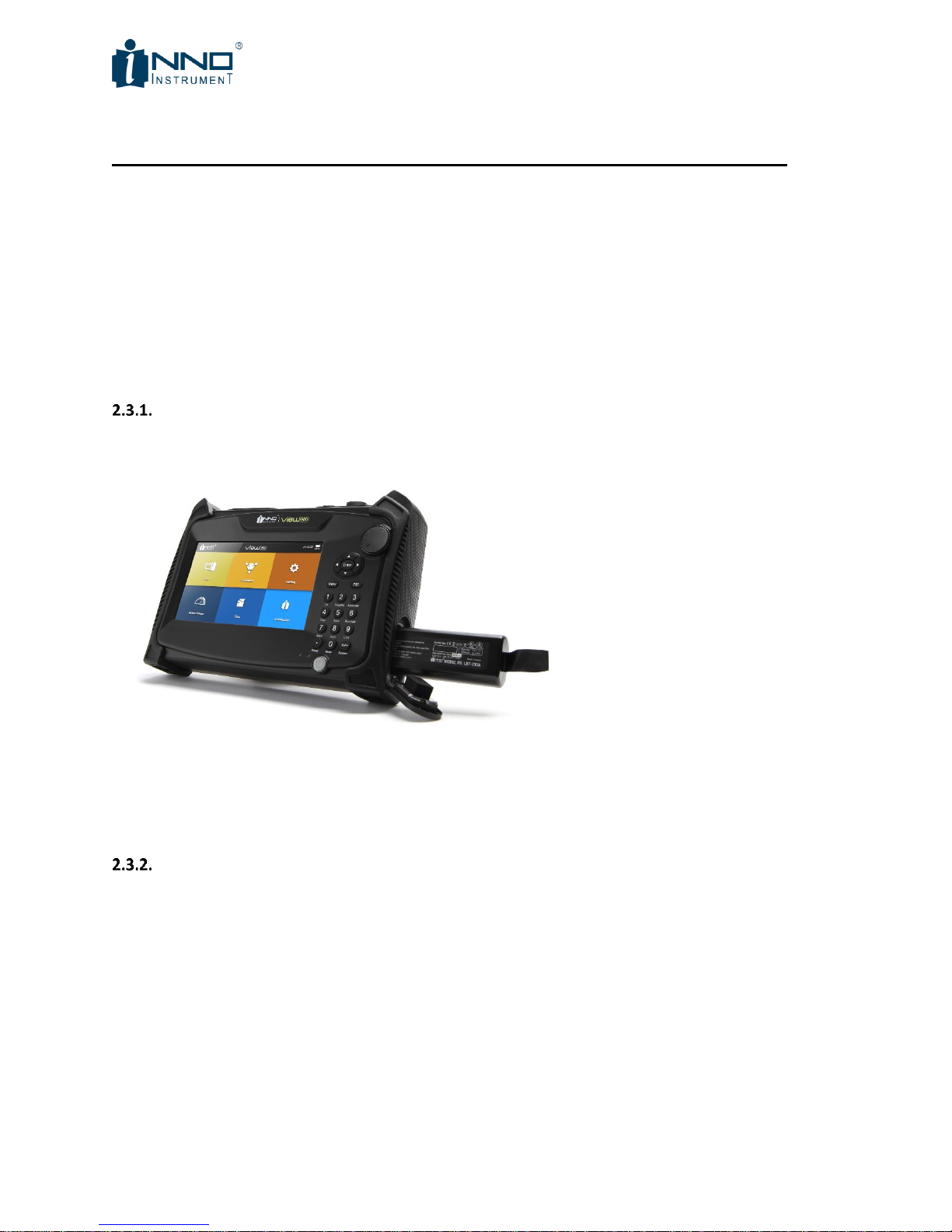
2.3. Battery
View900 uses the following Battery Pack:
Product
BATTERY PACK
Model No.
LBT-230A
Power Supply
7.4Vd.c. 7800MAh, 57.72Wh
Manufacturer
INNO INSTRUMENT (CHINA) INC.
Product
Power Unit
Model No.
INNO-PU-8
AC Input
100-240 Va.c. 50-60Hz
DC Output
12.0Vd.c. 3.0A Max
Manufacturer
INNO INSTRUMENT (CHINA) INC.
View900 Cable Antenna Analyzer User Manual
INNO Instrument Inc.
Page 15 of 69
Note
RISK OF EXPLOSION IF BATTERY IS REPLACED BY AN INCORRECT TYPE.
DISPOSE OF USED BATTERIES ACCORDING TO THE MANUFACTURER’S INSTRUCTIONS.
①When the “TEST” button on the battery is pressed, the remaining battery volume will appear
in the battery icon next to the “TEST” button.
②Each level of the battery indicates 20% of the battery charging status. (e.g. level 3 indicates
upto 60% charge.
③Insert the battery pack with the folloiwng instruction.
INSTALLING A BATTERY
Caution: Fully charge the battery before first using the instrument.
1. Slide down and pull battery cap to Open
2. Insert the battery pack
3. Close the battery cap
CHARGING A BATTERY
1. Insert a battery
2. Provide AC-DC Adaptor
3. Press power button to turn on
4. Check if a battery icon is displayed on the screen
View900 Cable Antenna Analyzer User Manual
INNO Instrument Inc.
Page 16 of 69
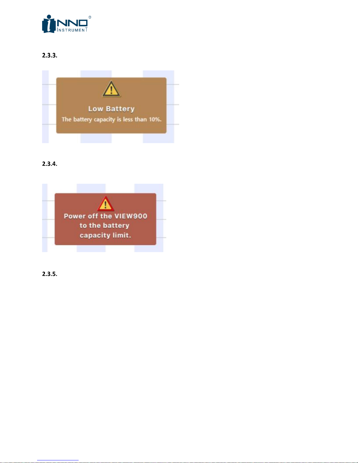
LOW BTTERY
Charge the battery or provide AC/DC adaptor immediately when the following lowe-battery warning appears:
AUTOMATIC POWER OFF WHEN BATTERY LOW
When the battery power is lower than 5%, the power will be off with the following message:
CAUTION
Do not store the battery pack in the high humidity and heat.
If electrolyte from the battery pack is leaking or the battery pack smells strangely, keep the battery pack
away from fire.
In case that electrolyte from the battery pack is touched by any part of the human body, wash it
immediately and go to hospital to prevent potential damage.
Use the authorized charger only.
Do not abandon the battery pack in the car in the summer.
Avoid any shock to the battery pack.
Avoid placing the battery pack near heating sources of on the place near windows.
If the battery is unused for a long time, separate it from the unit.
Keep this battery pack away from children
<French>
Ne pas stocker la batterie dans un niveau élevé d'humidité et de chaleur.
En cas de fuite d'électrolyte de la batterie ou si la batterie dégage une odeur étrange, éloignez la batterie
du feu.
Au cas où une partie quelconque du corps humain touche l'électrolyte de la batterie, lavez-la
immédiatement et rendez-vous à l'hôpital pour éviter des dommages potentiels.

View900 Cable Antenna Analyzer User Manual
INNO Instrument Inc.
Page 17 of 69
Utilisez uniquement le chargeur autorisé.
Ne pas abandonner la batterie dans une voiture en été.
Évitez tout choc sur la batterie.
Évitez de placer la batterie à proximité de sources de chaleur ou de fenêtres.
Si la batterie est inutilisée pendant une longue période, séparez-la de l'unité.
Gardez cette batterie hors de portée des enfants.

View900 Cable Antenna Analyzer User Manual
INNO Instrument Inc.
Page 18 of 69
3. MENU DECRIPTIONS
View900 Cable Antenna Analyzer User Manual
INNO Instrument Inc.
Page 19 of 69
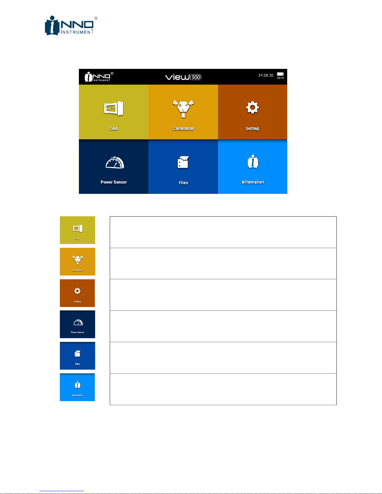
3.1. Menu Descriptions
-Run a ‘Cable & Antenna Analyzer mode
-Run ‘Calibration.’
-Select either Mechanical (OSL) Calibration or Electrical Calibration.
-Settings’ to configure measurement parameters
-‘Power Measurement with an external power Sensor.’
-‘Files’ menu to view saved data
-‘Information’ of the instrument
Table of contents
Other INNO Instrument Measuring Instrument manuals


