TechnipFMC Smith Meter Ultra C Series Operating and safety instructions

Smith Meter®
Ultra™ Series C Liquid Ultrasonic
Flowmeters
& MPU™ Series C Ultrasonic
Flowmeters
SoM Replacement Manual
Bulletin MN0A005 Issue/Rev. 0.0 (4/22)

Important
All information and technical specifications in this document have been carefully checked and
compiled by the author; however, we cannot completely exclude the possibility of errors.
TechnipFMC is always grateful to be informed of any errors; contact us at TechnipFMC.com.
Technical Support
Field Service Response Center
24/7 Technical Support/Schedule a Technician: +1 844.798.3819
System installation supervision, startup, and commissioning services are available.
Customer Support
Customer Service
TechnipFMC
Measurement and Production Solutions
1602 Wagner Avenue
Erie, PA 16510 USA
+1 814.898.5000
TechnipFMC.com
Literature Library
info.smithmeter.com/literature
SoM Replacement Manual
Bulletin MN0A005 Issue/Rev. 0.0 (4/22) ii

Contents
1 Introduction 1
1.1 Weights and Measures Requirements 1
1.2 Product Description 1
1.2.1 SoM Upgrade Kit Contents 2
1.3 Receipt of Equipment 2
1.4 Storage Instructions 3
1.5 Warnings and Precautions 3
1.5.1 Hazardous Locations 3
1.5.2 Electrostatic Discharge Precautions 4
2 Replacing the SoM 5
2.1 Required Tools 5
2.2 Backing Up Existing SoM Database 6
2.3 Removing the UMCB 6
2.4 Exchanging the SoM 8
2.5 Replacing Labels 10
2.5.1 Serial Number Label 10
2.5.2 Firmware Version Label 10
2.6 Re-Assembling the UMBC 11
2.7 Restoring the Database 11
3 Related Publications 12
SoM Replacement Manual
Bulletin MN0A005 Issue/Rev. 0.0 (4/22) iii

1 Introduction
This manual provides instructions for replacing the system on module (SoM) using the
SoM Upgrade Kit, located on the Ultrasonic Meter Control Board (UMCB) of the
following meters:
lUltra Series C Liquid Ultrasonic Flowmeter
lMPU Series C Ultrasonic Gas Flowmeter
This procedure assumes the appropriate Ethernet or fiber-optic communications
cabling are accessible in a safe area for connection between a PC and the sealed
UMCB enclosure that is mounted in the hazardous area.
1.1 Weights and Measures Requirements
TechnipFMC's Ultra and MPU series of ultrasonic meters are used in a global market.
Requirements regarding weights and measures may vary depending on the region of
installation and type of installation. In the majority of cases in which the meter is
controlled by a weights and measures certificate, the software version is defined and
controlled.
In the case of a controlled measurement application, users are required to verify that
the TechnipFMC Ultrasonic meter is configured and operated in a manner consistent
with the controlling certificate and local codes, and that proper notification (permit for
use) or registration has been filed with the local authority or jurisdiction. This
requirement also pertains to software updates of the meter.
Weights and measures authorities rely on either physical sealing or electronic sealing
with password protection to secure metrological parameters for use in legal trade
applications. For instructions on setting a passwords for metrological parameters and
information about physically sealing the electronic enclosure and specific meter
components, refer to the Ultra Series C Liquid Ultrasonic Flowmeters Installation,
Operation, and Maintenance Manual (MNLS005) or MPU Series C Installation,
Operation, and Maintenance Manual (MNKS025).
1.2 Product Description
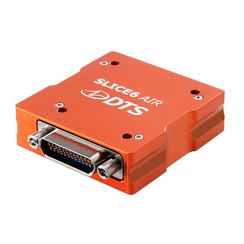
The SoM Upgrade Kit enables you to upgrade your SoM to run Ultrasonic Software
versions 2.0 and above. Ultrasonic Software version 2.0 improves critical processes,
Bulletin MN0A005 Issue/Rev. 0.0 (4/22) 1
SoM Replacement Manual

such as Ultrasonic Software updates, to be faster and more reliable.
Multiple SoM upgrade kits are available, depending on the version of your UMCB:
lP8000019905 SoM 2.0 upgrade kit for use in UMCB version 4.0 and UMCB-W
version 3 and above
lP8000019988 SoM 2.0 upgrade kit for use in UMCB version 3.0 and UMCB-W
version 2 and below
lP8000020133 SoM 2.0 upgrade kit (special Modbus) for use in UMCB version 3.0
and UMCB-W version 2 and below
P8000020134 SoM 2.0 upgrade kit (special Modbus) for use in UMCB version 4.0
and UMCB-W version 3 and above
The process of replacing the SoM is the same for all upgrade kits.
1.2.1 SoM Upgrade Kit Contents
All SoM upgrade kits include the following items:
lA new SoM programmed for Ultrasonic Software 2.0
lSoM-specific serial number label for placement on UMCB assembly
lAn anti-static wrist strap
lTweezers
lA PH1 Phillips head (cross-head) screwdriver
lUMCB shield SoM upgrade label
lTwo SoM mounting screws (spares)
lTwo SoM Spacers (spares)
1.3 Receipt of Equipment
When you receive your SoM Replacement Kit, you should check the exterior packing
case for any shipping damage.
If the packing case is damaged, contact the shipping carrier immediately regarding
their liability.
Bulletin MN0A005 Issue/Rev. 0.0 (4/22) 2
SoM Replacement Manual

Carefully remove the control board module from the exterior packaging and inspect it
for damaged or missing parts. For a list of parts included in the SoM Replacement Kit,
see Section 1.2.1: SoM Upgrade Kit Contents. The SoM module is packaged in an
antistatic, sealed, zipper storage bag; it should not be opened or the SoM should not
be handled without using the antistatic wrist strap.
Prior to installation, the unit should be stored in its original packaging and protected
from adverse weather conditions and abuse.
If the control board module is damaged or parts are missing, a written report must
be submitted to:
TechnipFMC
c/o Inside Sales Department, Measurement Solutions
PO Box 10428
Erie, PA 16514
1.4 Storage Instructions
To ensure your replacement SoM is not damaged by moisture or water before being
installed, it must be properly stored in a cool, dry, protected location and remain in its
resealable zipper antistatic bag.
1.5 Warnings and Precautions
Before you begin the process to replace the SoM, please read all of the following
warnings and cautions to reduce the risk of injury, equipment damage, or malfunction.
1.5.1 Hazardous Locations
The Ultrasonic Meter Control (UMC) assembly is approved for use in an explosive
environment or hazardous location. This manual only provides information pertaining
to the installation of the SoM replacement.
To maintain equipment safety, it is required to keep the front cover of the enclosure
bolted tightly while power is applied when operating in a hazardous location. The
closing and sealing of the enclosure is the key to maintaining explosion protection. It is
imperative that servicing be performed by a qualified individual who is familiar with
associated risks involved with the operation and maintenance of electrical equipment
in hazardous (classified) locations. This individual must have knowledge of local and
national electrical codes, in addition to ordinances concerned with hazardous location
Bulletin MN0A005 Issue/Rev. 0.0 (4/22) 3
SoM Replacement Manual

safety requirements. It is recommended (and may be required in some jurisdictions)
that the final installation be verified and inspected by the authority having jurisdiction
before placing the equipment back into service. Electrical installations in hazardous
areas have features specifically designed to make them suitable for use in such
locations and it is the operator’s responsibility to maintain the integrity of those special
features.
Warning: The electronics inside the explosion-proof enclosure are not suitable for
exposure in a hazardous area while power is applied. Proper precautions must be
taken before opening the enclosure when the meter and its electronics are
installed in a hazardous area. The area must be verified that hazardous gases or
vapors are not present, and all power to the equipment has been removed.
1.5.2 Electrostatic Discharge Precautions
The UMCB printed circuit board assembly is susceptible to damage by static
discharge. To minimize the risk of damage, the following precautions should be
followed:
lBefore touching a circuit board with hands or tools, personnel and tools should be
grounded using a wrist strap.
lAvoid touching components or traces on the circuit boards and handle by the
edges or mounting holes.
lCircuit boards should be kept in static control packaging, such as static shielding
bags, when not installed.
lProvisions should be made to protect against electrostatic discharge (ESD) in work
spaces when handling circuit boards.
Bulletin MN0A005 Issue/Rev. 0.0 (4/22) 4
SoM Replacement Manual

2 Replacing the SoM
Use the following process to replace a SoM using a SoM Replacement Kit.
Caution: Before working with the UMCB, ensure that the system is made safe for
work, removing energy sources, and tagging out, as required.
2.1 Required Tools
The tools needed to replace the SoM include:
lAn anti-static wrist strap (included in the SoM Replacement Kit)
lTweezers (included in the SoM Replacement Kit
l5 millimeter (mm) hexagon key wrench
l2.5 mm slotted (flat blade) screwdriver
l6.5 mm slotted screwdriver
lPH1 Phillips head screwdriver (included in the SoM Replacement Kit)
lPersonal computer (PC) with a web browser (Google Chrome is recommended)
lEthernet connection
lTechnipFMC Plotter Tool for Series C Ultrasonic Flow Meters version usmplot-
0.5.7-BETA or newer (contact your TechnipFMC service representative to get a
copy of this software)
Note: The external Ethernet connection should be available in an area where it is
safe to use a laptop computer. If this is not available, the UMCB board must be
removed the from the enclosure and taken to a safe area where it can be powered
on and connected to a PC. This procedure is based on performing the upgrade at
the meter's location; if the board needs to be removed to be taken to a safe area,
you should modify the steps below accordingly.
Bulletin MN0A005 Issue/Rev. 0.0 (4/22) 5
SoM Replacement Manual

2.2 Backing Up Existing SoM Database
Before replacing the SOM in the UMCB, you should back up the database to preserve
and verify the parameters so they can be restored to the new SOM after completing
the installation.
You will need a PC with a web browser (Google Chrome is recommended) and the
TechnipFMC Log Plotter Tool.
Complete following steps to back up the database:
1. Connect to the meter using a web browser and download the parameters to a USC
file; this file will be used to configure the new SoM to the meter.
2. Using the TechnipFMC Log Plotter Tool, open the USC file and determine whether
any parameters are missing. Missing parameters are highlighted in red; the status
bar indicates the number of missing parameters. If parameters are missing,
download the USC file again and re-verify.
When uploading this parameter file to the new SOM, the meter tag name will not
transfer. You must program this using a web browser after uploading the
parameters.
2.3 Removing the UMCB
Complete the following steps to remove the UMBC from the meter’s electronics
enclosure:
1. Verify that all power to the explosion proof enclosure is removed.
2. Remove the 10 M8 1.25 x 25 mm socket-head cap screw cover bolts with a 5 mm
hexagon key wrench and open the electronics enclosure.
3. Following the instructions on the anti-static wrist strap’s packaging, ground the
strap by attaching one end of the anti-static strap to your wrist and attaching the
other end of the strap to a suitable grounding point in the area close to the
enclosure.
Bulletin MN0A005 Issue/Rev. 0.0 (4/22) 6
SoM Replacement Manual

Figure 1: Grounded Anti-Static Wrist Strap
4. Using a 2.5 mm slotted screwdriver, loosen the two captive screws from the
UMCB’s power supply connector CN1 and unplug the connector. This step can be
done for the remaining field wiring connectors if you need to remove cable
connections to allow removal of the UMCB board from the enclosure housing.
5. If equipped, loosen the two captive screws for the touch screen’s connectors using
a 2.5 mm slotted screwdriver.
It is important to remember or make a note of the position of all cable
connectors removed from the UMCB board assembly so you can replace them
in the proper location after the SoM replacement procedure.
6. Remove any additional cables connected to the UMCB, such as any Ethernet or
fiber-optic communications cables.
Do not disconnect the transducer cables.
Bulletin MN0A005 Issue/Rev. 0.0 (4/22) 7
SoM Replacement Manual

Figure 2: UMCB
7. While supporting the UMCB with one hand, remove the four mounting screws
using the 6.5 mm slotted screwdriver.
8. Remove the UMCB from its enclosure (without disconnecting the transducer
cables) and gently rotate it to set it down on the cover of the meter.
2.4 Exchanging the SoM
Complete the following steps to exchange the SoM:
When removing the SoM, do not touch the gold-plated contacts.
1. Ensure the UMCB is placed with the bottom of the board facing up and supported
on the flat, top surface of the meter cover.
2. Using a PH1 Phillips head screwdriver, remove the two screws that secure the
SoM to the UMCB.
3. The SoM also is secured with a spring latch connector. Carefully push both sides
of the connector’s clips outward at the same time to release the SoM from the
UMCB.
The SoM can inadvertently pop out of the connector when removing it.
Bulletin MN0A005 Issue/Rev. 0.0 (4/22) 8
SoM Replacement Manual

Figure 3: Removing the Old SoM
4. Remove the SoM from the connector, ensuring that you only touch the edges of
the module.
5. Remove the two spacers between the SoM and the UMCB.
Failing to remove these spacers may result in damage to the circuit boards
when installing the new SoM.
6. Slide the new SoM into the module connector at a slight angle. The SoM is
correctly placed when its connection to the board is completely in the socket.
Figure 4: Inserting the New SoM
Bulletin MN0A005 Issue/Rev. 0.0 (4/22) 9
SoM Replacement Manual

7. Gently press the SoM down until the two clips snap into place. Ensure that you do
not force the SoM into place.
8. After the SoM is seated, re-position the spacers using tweezers. The spacers must
be placed between the boards and aligned with the screw holes.
9. Using a PH1 Phillips head screwdriver, re-insert the two screws that secure the
SoM to the PCB. Be sure not to over-torque the screws.
10. Verify the position of the spaces to ensure they are properly aligned with the pads;
improper alignment can damage the PCB or SoM traces.
2.5 Replacing Labels
Two new labels, a serial number label and a firmware revision label, are packaged
with the programmed SoM to be used when it is permanently attached to the UMCB
board assembly. The serial number for the SoM will be read from the Meter Info page
in the web browser.
2.5.1 Serial Number Label
The serial number is on the first line and the software version and check sum are on
the second line. For example,
Figure 5: Firmware Revision and CRC Label
This label should be placed over the old label located on the fiber-optic converter.
2.5.2 Firmware Version Label
The firmware version label with a QR code should be placed over the old QR code
label located on the UMCB shield.
Figure 6: Firmware Version Label
Bulletin MN0A005 Issue/Rev. 0.0 (4/22) 10
SoM Replacement Manual

2.6 Re-Assembling the UMBC
After replacing the SoM, complete the following steps to re-assemble the UMBC:
1. Verify that the power is turned off.
2. Gently rotate the PCB and place it into the enclosure.
3. While supporting the UMCB with one hand, attach the four mounting screws using
a 6.5 mm slotted screwdriver.
4. Connect the Ethernet cable.
5. Re-attach any additional cables connectors that were previously removed.
6. Using a 2.5 mm slotted screwdriver, tighten the two captive screws to attach the
UMCB’s power supply connectors.
Ensure that all connectors are re-attached in their original position and the
captive screws are tightened.
7. Using a 2.5 mm slotted screwdriver, tighten the two captive screws to attach the
touch screen’s connectors (if equipped).
8. Using a 5 mm hexagon key wrench, close the electronics enclosure and secure it
with the 10 M8 1.25 x 25 mm socket-head cap screw cover bolts.
2.7 Restoring the Database
Restoring the database requires an external Ethernet connection available in an area
that is safe to use a laptop computer. If this is not available, the UMCB board must be
removed the from enclosure and taken to a safe area where it can be powered on and
connected to a PC.
Complete the following steps to restore the backed-up database:
1. Power up the UMCB. Be sure to follow the precautions noted in section 1.5.1:
Hazardous Locations.
2. Connect to the meter using a web browser (Google Chrome is recommended) and
upload the parameter file from the previously created USC file.
When uploading this parameter file to the new SOM, the meter tag name will not
transfer; you will need to program this a the web browser after uploading the
parameters.
Bulletin MN0A005 Issue/Rev. 0.0 (4/22) 11
SoM Replacement Manual

3 Related Publications
The following literature can be obtained from TechnipFMC Measurement Solutions
Literature Fulfillment at Measureme[email protected] or online at
info.smithmeter.com/literature/online_index.html.
When requesting literature, please reference the appropriate title and document
number, as follows:
lUltra Series C Liquid Ultrasonic Flowmeters Installation, Operation, and
Maintenance Manual (MNLS005)
lMPU Series C Installation, Operation, and Maintenance Manual (MNKS025)
Bulletin MN0A005 Issue/Rev. 0.0 (4/22) 12
SoM Replacement Manual

Notice
All procedures, data, information, drawings, specifications or other material, whether accompanying this document or separately supplied in
furtherance of this document, contain confidential and proprietary information which (i) is the property of TechnipFMC plc (TechnipFMC) and its
subsidiaries, (ii) is disclosed by TechnipFMC only in confidence, and (iii) except as TechnipFMC may otherwise permit in writing, is to be used,
disclosed or copied only to the extent necessary for the evaluation and use thereof by the recipient.
The foregoing shall not apply to any such material to the extent that the contents (i) are now or subsequently become available to the public
without payment, (ii) were previously known to the recipient, or (iii) subsequently become otherwise known to the recipient without restriction.
This document is based on information available at the time of its publication. While efforts have been made to be accurate, the information
contained herein does not purport to cover all details or variations in hardware and software, nor to provide for every possible contingency in
connection with installation, operation and maintenance.
TechnipFMC makes no representation or warranty, either expressed or implied, with respect to, and assumes no responsibility for, the
accuracy, completeness, or sufficiency of the information contained herein. No warranties of merchantability or fitness for a particular purpose
shall apply.
Smith Meter is a registered trademark. The TechnipFMC logo is a trademark.
This document takes precedence over and supersedes in their entirety all previous versions or revisions.
Bulletin MN0A005 Issue/Rev. 0.0 (4/22)
Copyright © 2022 TechnipFMC plc. All rights reserved.
TechnipFMC.com
TechnipFMC Corporate Headquarters
13460 Lockwood Road
Building S01
Houston, TX 77044 USA
+1 281.591.4000
USA Operations
1602 Wagner Avenue
Erie, PA 16510 USA
+1 814.898.5000
Germany Operations
Smith Meter GmbH
Regentstrasse 1
25474 Ellerbek, Germany
+49 4101 304.0
This manual suits for next models
1
Table of contents
Other TechnipFMC Measuring Instrument manuals

TechnipFMC
TechnipFMC Smith Meter PRIME 4 User manual
TechnipFMC
TechnipFMC Smith Meter AccuLoad IV Series Manual
TechnipFMC
TechnipFMC Smith Meter MPU C Series Instruction manual
TechnipFMC
TechnipFMC Smith Meter AccuLoad IV Instruction Manual
TechnipFMC
TechnipFMC Proline Promass F 500 Instruction Manual
TechnipFMC
TechnipFMC Smith Meter User manual
TechnipFMC
TechnipFMC Smith Meter C2 User manual
TechnipFMC
TechnipFMC Smith Meter Genesis Series User manual
TechnipFMC
TechnipFMC Smith Meter JB10 S1 User manual

TechnipFMC
TechnipFMC Smith Meter Instruction manual
