INNO Instrument View 8+ User manual

User's Manual
Version:V0.01

User’s Manual
INNO Instrument, Inc.
01
PAGE
Preface....................................................................................................................................4
Chapter1 Technical Parameters.................................................................................................5
Applicable Fiber Type....................................................................................................................5
Splice Loss....................................................................................................................................5
Splice Mode...................................................................................................................................5
Heat Oven.....................................................................................................................................5
Power Supply.................................................................................................................................5
Size and Weight.................................................................................................................6
Environmental Conditions.........................................................................................................6
Others............................................................................................................................................6
Battery precautions...................................................................................................................6
Chapter 2 Installation.....................................................................................................................7
Safety Warning and Precautions...................................................................................................7
Safety Warnings......................................................................................................................7
Maintenance and External Care Precautions........................................................................8
Transport and Storage Precautions..........................................................................................8
Installation upon Delivery............................................................................................................8
Unpacking the Splicer................................................................................................................8
Overview of External Parts ...........................................................................................................9
Power Supply Method............................................................................................................10
Chapter 3 Basic Operation.......................................................................................11
Turn On the Splicer.................................................................................................11
Adjust Monitor Angle...............................................................................................11
Adjust LCD Backlight Brightness......................................................................12
Preparing the Fiber..........................................................................................13
How to Make a Splice...........................................................................................14
Put the optical fiber in..........................................................................................14
Contents

User’s Manual
INNO Instrument, Inc.
02
PAGE
Inspecting the Fibers........................................................................................14
Splicing............................................................................................................15
How to Protect the Splice.......................................................................................15
Steps for Heating....................................................................................................15
Chapter 4 Splice Mode..........................................................................................17
Displaying the Current Splice Mode......................................................................17
Selecting a Splice Mode......................................................................................18
Steps of Normal Splicing Program........................................................................19
Pre-Fusion............................................................................................................19
Fusion.....................................................................................................................19
Splicing Process.....................................................................................................19
Parameters for Normal Splicing Process.................................................................20
Chapter 5 Splice Option.....................................................................................22
Splice Mode Setting..........................................................................................22
Chapter 6 Heater Mode.............................................................................24
Select Heat Mode.......................................................................................24
Edit Heater Mode..........................................................................................25
Delete Heat Mode....................................................................................26
Heater Mode Parameters........................................................................26
Chapter 7 Maintenance Menu...........................................................................27
Replace Electrodes..........................................................................................27
Replacement Procedure..................................................................................27
Stabilize Electrodes..........................................................................................28
Operation Procedure..........................................................................................28
Diagnostic Test.....................................................................................................28
Operation Procedure..........................................................................................28
Dust Check...................................................................................................29
Operation Procedure....................................................................................29

User’s Manual
INNO Instrument, Inc.
03
PAGE
Motor Calibration..........................................................................................29
Operation Procedure..........................................................................................30
Arc Calibration........................................................................................................30
Operation procedure..........................................................................................30
Electrode Setting....................................................................................................30
Update Software..........................................................................................30
Chapter 8 Other Functions & Utilities.....................................................................31
WIFI Connection.....................................................................................................31
Data Storage..........................................................................................................34
Display Splice Record..........................................................................................34
Delete Splice Record...........................................................................................34
Cancel Data Storage..........................................................................................34
System Setting.......................................................................................................34
Monitor Position.................................................................................................35
Power Save Option..........................................................................................36
System Information..........................................................................................36
Appendix I............................................................................................................37
Appendix II............................................................................................................39
Appendix III............................................................................................................42

User’s Manual
INNO Instrument, Inc.
04
PAGE
Thank you for choosing VIEW8+ Arc Fusion Splicer from INNO Instrument. VIEW8+
adopts innovative product design and exquisite manufacturing technology so as to
deliver unprecedented splicing experience to customers.
The totally new technology greatly reduces splicing and heating time, and
advanced estimation method and alignment technique ensure the accuracy of
splice loss estimation. The simple-but-trendy product design, sophisticated internal
structure and reliable durability make the splicer be suitable for any operating
environment. Dynamic operation interface and automatic splice mode provide users
great convenience.
For more information of VIEW8+, please visit our ofcial website at
www.innoinstrument.com
Equipped with FH-40 ber holder
(Standard package)
Model: FH-40
This User Manual explains the use, performance characteristics, and cautions
about VIEW8+ fusion splicer and how to install and operate it. The primary goal of
this manual is to make the user as familiar with the splicer as possible.
Important!
INNO Instrument recommends all users to read this manual before operating
VIEW8+ fusion splicer.
Preface

User’s Manual
INNO Instrument, Inc.
05
PAGE
* SM(ITU-TG.652&G.657)/MM(ITU-TG.651)/DS(ITU-TG.653)/NZDS(ITU-
TG.655)
* Fiber count: Single
* Applicable fiber / cable diameter: 0.25mm to 3.0mm/Indoor Cable
* Applicable fiber diameter: Cladding diameter: 80mm to 150μm / Coating
diameter:125 to 1000μm
Same ber is spliced, measured by cut-back method relevant to ITU-T standard.
The typical values of splice loss are:
*SM:0.02dB
*MM:0.01dB
*DS:0.04dB
*NZDS:0.04dB
*G.657:0.02dB
* 5 kinds of applicable protection sleeve: 20mm, 30mm, 40mm, 50mm, 60mm
* Heating time: 20 to 900s optional.
* Typical heating time: 20s.
* Fast heating time: 9s.
* Heating mode: various in-built heat modes available
* Heater: Specific heater for VIEW8+ fusion splicer.
* It can be preset 45 kinds of splice mode.
* It can store 10000 records of the latest splice results.
* Splice time: SM Quick mode: 6s.
Chapter1 Technical Parameters
Applicable Fiber Type
Heat Oven
Splice Loss
Splice Mode
* Standard AC power voltage: AC 100 to 240V, 50 to 60Hz;
* Standard DC power voltage: DC 19V to 3.42A
Power Supply
* Size:Length×width×height= 157mm×144mm×162mm
* weight:2.78kg (battery included)
Size and Weight

User’s Manual
INNO Instrument, Inc.
06
PAGE
* Operating conditions: altitude: 0 to 5000m, relative humidity: 0 to 95%,
temperature: -10 to50 ℃ , the maximum wind velocity: 15m / s;
* Storage conditions: relative humidity: 0 to 95%, temperature: -20 to 60 ℃ ,
battery: -20 to 30 ℃ for long-term storage
* Observation and display: Two cameras, 5.0-inch color LCD display
* 320x magnification for single X or Y view, or 180x magnification for both X and Y
view.
* Tensile test:1.96 to 2.25N.
* Terminals: USB2.0/MINI USB
1) Do not touch or hit battery with pointed or sharp items.
2) Do not transport or store the battery together with metals.
3) Do not throw, drop, impact, or bend battery, or any knock or stomp on the battery is
forbidden.
4) Do not connect the anode and cathode terminals of the battery with metals such as
electric wire for fear of short circuit trouble.
5) Do not allow battery’s anode or cathode terminal to touch with the aluminum layer
of package made from aluminum laminated plastic film material for fear of short-circuit.
6) In no case the battery cell can be dismantled.
7) Do not immerse the battery into water or seawater, because the battery cell cannot
bear moist environment.
8) Do not place or use the battery beside or near the heat source such as fire or heater.
9) Do not heat battery or throw it into water.
10) Do not directly solder the battery.
11) Do not charge battery near or beside the fire or in a very hot environment.
12) Do not place the battery into microwave oven or any high pressure vessel.
13) Do not allow the battery work or place it in hot temperatures such as in strong
sunshine or hot environment in car for a long time, for fear that battery might be
overheated, on fire, weakened functionally, or shortened in life.
14) Any usage of the damaged battery is forbidden. The battery should be kept away
from fire source when electrolyte leakage occurs or the battery emits electrolyte smell
for fear battery might catch on fire or explode.
Environmental Conditions
Other
Battery precautions

User’s Manual
INNO Instrument, Inc.
07
PAGE
As VIEW8+ is designed for fusion splicing silica glass optical bers, it is very important
that the splicer should not be used for any other purposes. The splicer is a precision
instrument and must be handled with caution. Therefore, you must read the following
safety rules and general precautions in this manual regarding the use and handling of
VIEW8+ at any time. Any behaviors that do not follow the warnings and cautions will
break the safety standard about design, manufacture, and usage of the fusion splicer.
INNO Instrument will not take the responsibility for those consequences caused by
misuse!
①Never operate the splicer in an environment where flammable liquids or vapors
exist.
②DO NOT touch the electrodes when the splicer is on.
Note: Only use specified electrodes for the fusion splicer. Select
[Replace electrode] in maintenance menu to replace electrodes, or turn
off the splicer and disconnect the AC power source or remove battery
before replacing electrodes. Discharging is prohibited before the
electrodes are placed as a pair.
Chapter 2 - Installation
Safety Warning and Precautions
Operational Safety Warnings
③ DO NOT disassemble or modify any components of the splicer without approval, except for
the permitted-to-disassemble / modify components or parts by users stated in this manual.
Component replacement and its internal adjustment must be implemented by INNO or its
authorized technicians or engineers.
④ Never operate the splicer in an environment where fammable liquids or vapors exist.
Risk of dangerous fire or explosion could result from the splicer’s electrical arc in such an
environment. DO NOT operate the splicer near heat source or in high temperature and dusty /
humid atmosphere, or when condensation is present on the splicer. This may result in electric
shock, splicer malfunction, or poor splicing performance.
⑤ Safety glasses should always be worn during fiber preparation and splicing operation. Fiber
fragments can be extremely dangerous if they come into contact with the eye, skin, or are
ingested.
⑥ Take out the battery immediately if the followings are observed when using the splicer:
* Fumes, bad smell, abnormal noise or over heat.
*Liquid or other matter falls into cabinet
*The splicer is damaged or dropped.
If any of these faults occurs, please contact our service center immediately. Leaving the splicer
in a damaged state without any prompt measures may cause equipment failure, electric
shock, or fire and may result in injury or death.
⑦ Do not use compressed gas or canned air to clean the splicer. They may contain
flammable materials that could ignite during the electrical discharge.
⑧ Please use VIEW8+ specific standard battery only. Using an improper AC power source
may cause fuming, electric shock or equipment damage and may even result in fire, injury or
death.
⑨ Please use VIEW8+ specific charger only. Do not place any heavy objects on the AC
power cord. Keep the power cord away from heat source. Using an improper cord or a
damaged cord may cause fuming, electric shock or equipment damage and may even result
in fire, injury or death.

User’s Manual
INNO Instrument, Inc.
08
PAGE
Maintenance and External Care Precautions
Transport and Storage Precautions
Unpacking the Splicer
① Always avoid using hard objects to clean V-grooves and electrodes.
② Always avoid using acetone, thinner, benzol or alcohol when cleaning any part of
the splicer, except for the places advised.
③ Use a dry cloth to remove dust and dirt from the splicer.
④ If the outside of the splicer is dirty, plunge a soft cloth into diluted neutral
washing up liquid, wring out the cloth and clean. Dry the splicer with a dry cloth but
DO NOT use furniture polish or other cleaning agents.
⑤ Always follow the maintenance instructions in this manual.
① When the splicer is moved from cold to warm environment, you should allow the
splicer to warm up gradually. Otherwise, the condensation generated inside will
bring harmful effects to the splicer.
② Pack the fusion splicer well for long time storage.
③ Keep the splicer clean and dry.
④ The splicer is precision adjusted and aligned. Always keep the splicer in its
carrying case to protect from damage and dirt. Put cushion package outside the
carrying case for long distance transportation.
⑤ Always avoid leaving the splicer in direct sunlight or expose to excessive heat.
⑥ DO NOT store the splicer in dusty or humid environment. This may result in
electric shock, splicer malfunction or poor splicing performance.
⑦ Keep the humidity to a minimum level where the splicer is stored. The humidity
must not exceed 95%.
Hold the handle upwards, and then lift the splicer out of the carrying case. As
shown below.
Important!
Follow these instructions carefully.
Installation
User’s Manual
INNO Instrument, Inc.
09
PAGE
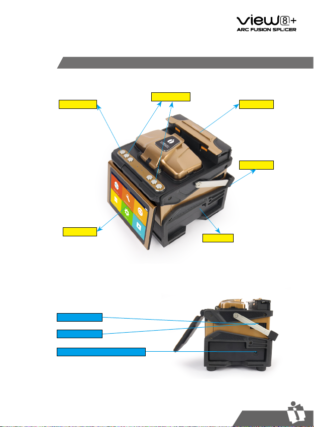
Overview of External Parts
Heat oven
Display
Battery
Handle
ON/OFF button
Control buttons
MINI USB
Power supply connector
USB 2.0
User’s Manual
INNO Instrument, Inc.
10
PAGE
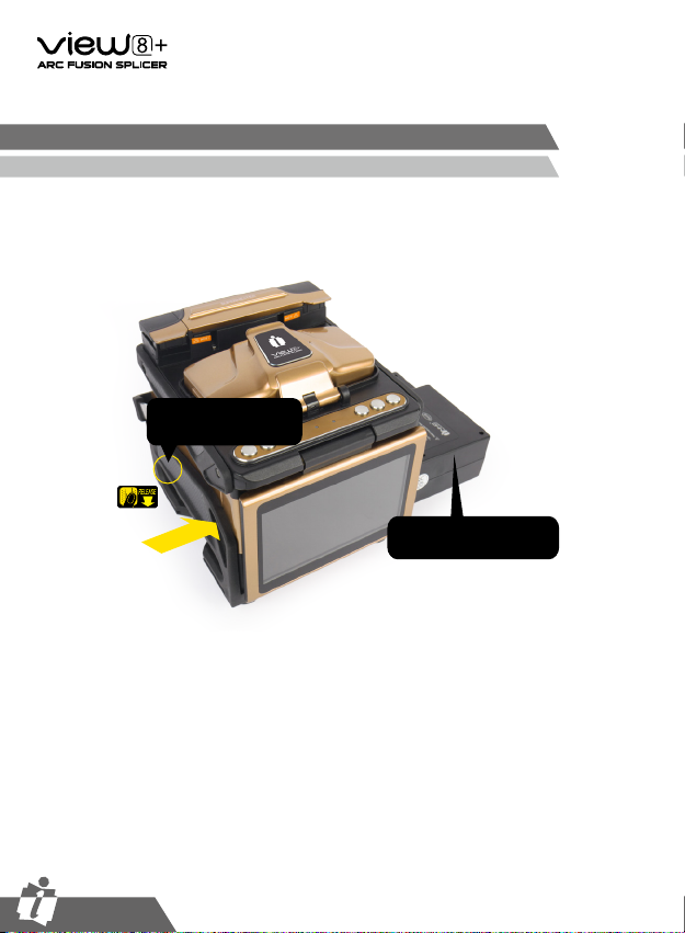
1. Following is the way of installing a battery.
Power Supply Method
Battery
Shut off fusion splicer. Press on
release button at lateral, drawing
power supply unit out of the
fusion splicer.
Place power supply unit into power
unit slot until you push it into the
right place.
Draw power supply unit
Release Button

User’s Manual
INNO Instrument, Inc.
11
PAGE
Chapter 3 - Basic Operation
Turn On the Splicer
Users can adjust the monitor position by moving it with a desired angle for purpose
of operation convenience.
Press button on the operation panel, and wait the splicer to be turned on and
move to Workbench page.
Adjust Monitor Position

User’s Manual
INNO Instrument, Inc.
12
PAGE
In the initial interface,press 【O】button on the operation panel to enter monitor
brightness adjustment interface, and press and to adjust the brightness until
a clear image can be seen.
Note: The LCD monitor is a precise component produced by
manufacturing factory under strict quality control. However,
some tiny dots in different colors may still remain on the screen.
Meanwhile, the screen brightness may not appear uniform,
depending on its viewing angles. Note that these symptoms are
not defects, but are natural phenomenon.
Users can zoom in the fiber image by double tapping on the screen so as to
observe the splicing result and check the splicing condition.
Fiber Zoom Function on Screen

User’s Manual
INNO Instrument, Inc.
13
PAGE
Note: always remember to slip a
heat-shrinkable sleeve onto either
end of the fibers at the beginning
of each fiber preparations.
3 steps should be carried out before splicing:
1. Stripping
Remove at least 50mm of secondary coating (valid for both tight and loose tube
secondary coating) and approximately 30~40mm of primary coating with an
appropriate stripper.
2.Clean bare fibers with pure alcohol-soaked gauze or lint-free tissue.
3.Cleave the fiber
In order to ensure the best splicing result, cleave the fbers with high precision
cleaver such as INNO Instrument V series fiber cleaver, and strictly control the
cleaving lengths shown as below.
Preparing the Fiber
Important!
Make sure that the bare fiber and its
cleaved section are clean.
-Avoid putting the fibers down on a
dusty working surface
-Avoid waving the bers around in the air
-Check if the V-grooves are clean; if
not, wipe them clean with pure alcohol-
soaked cotton swab.
-Check whether the clamps are clean; if
not, wipe them clean with pure alcohol-
soaked cotton swab.
use blue V-grooves
(Clamping on bare fiber)
User’s Manual
INNO Instrument, Inc.
14
PAGE
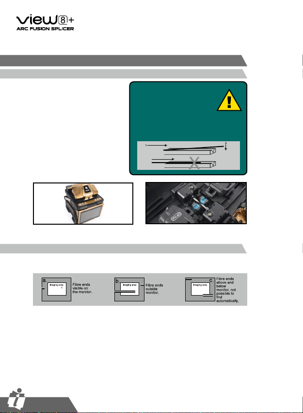
① Open the safety shield.
② Raise the fiber clamps.
③Position the fibers into V-grooves.
Make sure the fiber ends are
between the V-groove edges and
the electrode tip.
④ Clamp the fiber in position by
lowering both sets of fiber clamps.
⑤ Close the safety shield.
Before continuing with splicing, inspect the fibers whether they are clean and well-
cleaved. If any defects are found, please remove the fibers and prepare again.
How to Make a Splice
Put the optical ber in
Inspecting the Fibers
Note: Make sure to avoid sliding
the fibers along V-grooves,
but rather position them over
V-grooves and tilt them down
into place (as shown below).

User’s Manual
INNO Instrument, Inc.
15
PAGE
① Select any appropriate
splice mode.
② Start splicing by pressing
“SET” button.
After splicing, put the fiber with heat-shrink sleeve into the heat oven. Press [H]
button to execute heat-shrink process to strengthen the splice point.
① Open the heat oven lid
② Lift the left and right fiber holders on the splicer. Hold the heat-shrink sleeve
(previously placed onto the fiber). Lift the spliced fibers and hold them taut. Then
move the heat-shrink sleeve to the splice point.
③ Place the fiber with heat-shrink sleeve in the heat oven clamp.
④ Press [H] button to start heating. Upon completion, the heating LED indicator will
go off with buzzing.
Lip
Note:The fibers are checked automatically
when you press Set button. The splicer
automatically focuses the fibers and checks
for damage or dust particles.
Note: If the splicer is set as “Auto mode”,
splicing will start automatically once the
safety shield is closed.
Splicing
Heating Procedure
How to Protect the Splice

User’s Manual
INNO Instrument, Inc.
16
PAGE
Splicing position
move into heat oven clamp
Open the heat oven lid

User’s Manual
INNO Instrument, Inc.
17
PAGE
VIEW8+ has an intuitive and simple but very powerful program structure to operate.
Splice programs dene arc currents, splice times as well as various parameters
used when performing a splice. Therefore, it is essential to select the correct
splice program. There are a number of “Preset” splice programs for common
ber combinations. Therefore, it is much easier to modify and further optimize the
parameters for more unusual ber combinations.
Displaying the Active Splice
The active splice program is always displayed at the top of the screen (see below).
Displaying the active splice program
Chapter 4 Splice Mode

User’s Manual
INNO Instrument, Inc.
18
PAGE
①Select [Splice mode]
from the main menu.
②Select [Splice mode]
and select [Select splice
mode].
③ Select an appropriate
splice mode
④Selected splice mode
appears on the screen.
Press [RESET] button to
return to initial interface
page.
Selecting a Splice Mode

User’s Manual
INNO Instrument, Inc.
19
PAGE
General Splicing Steps
This section explains the steps involved in automatic splicing process and
describes how various program parameters are related to this process. The normal
splicing process can be divided into two sections: pre-fusion and fusion.
During pre-fusion, the splicer performs automatic alignment and focusing, where
the bers are subjected to a low pre-fusion current for cleaning purposes; a pre-
fusion image is also taken. At this point, the user is informed of any problems
recognized in the pre-fusion image, such as a poorly prepared ber. The splicer will
then issue a warning before the bers are fused together.
During fusion, the bers are joined together and subjected to ve different currents
as illustrated below. An important parameter, which changes during splicing, is
the distance between the bers. During Pre-fusion, the bers are apart. With the
current phase changing, bers are spliced gradually.
Arc power and arc time are considered as the two most important parameters (as
shown in the gure below). The name and purpose of those parameters as well as
the effect and importance of the parameters will be described in the next section
“Splice program parameters under general splicing process”. The below figure
shows the arc discharge conditions (relationship between “Arc power” and “Motor
motion”). These conditions can be modied by changing the splicing parameters
listed below. However, depending on the splice mode, certain parameters cannot
be changed.
Diagram of ARC discharge condition
A: Pre-fuse power B: Arc1 power C: Arc2 Power D: Cleaning Arc
E: Pre-fuse Time F: Forward Time related to Overlap G: Arc1 time
H: Arc2 ON time I: Arc2 OFF time J: Arc2 time
K: Taper Splicing Wait Time L: Taper Splicing Time
M: Taper Splicing speed N:Rearc Time
Pre-Fusion
Fusion
Splicing Process
Table of contents
Other INNO Instrument Welding System manuals


Popular Welding System manuals by other brands


Lincoln Electric
Lincoln Electric Power MIG 215 Operator's manual

Ritmo
Ritmo STARGUN SOLO 20 Operation and Maintenance Handbook

Lincoln Electric
Lincoln Electric Pro-Cut 55 Service manual

NewArc
NewArc Viper2500s instruction manual

Hot Max
Hot Max ARC100 Operator's manual

Juba
Juba BX1-B Series Operation manual