INNO Instrument IFS-10 User manual

1
Please read this manual before operating your
fusion splicer, and keep it for future reference.
2013/06 Rev.1.0
ARC Fusion Splicer
IFS-10 User Manual

1
IFS-10
User Manual

2

3
Contents
Introduction
Scope and purpose of the manual
The reader
IFS-10 Arc fusion splicer
Chapter 1: Installation
Safety warnings and precautions
Operational safety warnings
Maintenance and external care precautions
Transport and storage precautions
Installation upon delivery
Unpacking the splicer
The IFS-10 splicer standard
Optional accessories for IFS-10
Overview of external parts
The power connection
General
Mounting the power source
The power supply
General
Charging the battery
Power source and battery status
The heat oven
Chapter 2: Basic Operation
Quick guide
Preparing the splicer
Connecting the power supply
Cleaning V-grooves
Replace electrodes
7
7
7
7
8
8
9
9
9
10
10
10
11
12
13
13
13
13
13
14
15
16
17
17
18
18
18
18

4
Preparing the ber
How to strip the ber
How to clean the ber
How to cleave the ber
How to make a splice
Inserting the bers
Inspecting the bers
Splicing
How to protect the splice
Prepare to move ber from the splicer to the oven
Moving the ber to the heat oven
Shrinking
Resetting the ber movement motors
Chapter 3: Splice Programs
General
Displaying the active splice program
Selecting a splice program
Editing a splice program
Copying a splice program
The steps of the normal splicing process
Pre-fusion
Fusion
Summary
Splice program parameters, normal splicing process
Chapter 4: Other Functions & Utilities
General
Heater mode
Selecting heater mode
Referring or editing heater mode
Splice option
Data storage
System setting
18
19
19
20
21
21
21
22
22
22
23
24
24
25
25
26
26
26
27
27
27
28
28
28
31
31
32
32
33
34
35
36
Contents

5
Monitor position
Power save
Maintenance menu
Replace electrodes
Stabilizing electrodes
Diagnostic test
Dust check
Motor calibration
Arc calibration
Operation procedure
System information
Troubleshooting
Power supply
Splicing operation
Tube-heating operation
Supervising
Other functions
37
37
38
38
39
40
41
41
42
42
43
44
44
45
47
47
48
Contents

6
Important: INNO Instrument strictly recommends all users to read this manual
before operating IFS-10 splicer.
This manual is valid for the following software version:

7
Introduction
Scope and purpose of the manual
This User Manual explains how to install and operate IFS-10 fusion splicer. The
primary aim of this manual is to make the user as familiar with the splicer as
possible. Basic maintenance procedures are also described in Chapter 6
“Maintenance” to enable the user to keep the IFS-10 in excellent working
condition.
The reader
Inexperienced users can learn how to carry out basic splicing with IFS-10 as
described in Chapter 2 ‘Basic operation’. Experienced users will be able to extend
their knowledge by learning how to change parameters, implement utilities, etc.
Once the main routines and procedures have been learned, “Quick guide” in
Chapter 2 serves as a fast reminder of how to use IFS-10.
IFS-10 Arc fusion splicer
The most advanced eld fusion splicer from INNO Instrument, the IFS-10
delivers ultra fast splicing time and has an incredibly short shrinking time. The
prole alignment technique is combined with extremely accurate splice loss
estimation to ensure a precise alignment process. A new shrinking technology
means that the shrink time is greatly reduced, thus resulting in an extremely fast
total cycle time. The splicer is designed to withstand harsh environmental
conditions. Its lightweight, yet robust, compact and ergonomic design allows
users to easily carry or move. IFS-10 has a menu-driven user interface with
dynamic function buttons and a fully automatic splice process. For more product
information, contact your local distributor or visit our website at
www.innoinstrument.com

8
Installation
Scope and purpose of the manual
This chapter contains the following information:
•Safety warnings and precautions
•Operational safety warnings
•Maintenance and external care precautions
•Transport and storage precautions
•Installation upon delivery
•Unpacking the splicer
•Removing the cover
•IFS-10 splicer standard delivery kit
•Optional accessories
•Tool set
•Overview of external parts
•Power connection
•Mounting the power source
•Power supply
•Battery
•Charging the battery
•Power source and battery status
•Heat oven
•Mounting the heat oven
Safety warnings and precautions
As IFS-10 is designed for fusion splicing silica glass optical bers, it is very
important that the splicer should not be used for any other purpose. The splicer
is a precision instrument and must be handled with caution. Therefore, you must
observe the following safety rules and general precautions regarding the use and
handling of IFS-10 at any time.
1

9
Operational safety warnings
•Do not use the splicer in places where there is a risk of explosion.
•Do not touch the electrodes when the splicer is switched on.
•To avoid an electric shock, Do not open the back of the splicer or the power
supply. There are no user-serviceable parts inside the splicer, so refer any service
of the splicer to qualied personnel.
•Handle the main supply cable carefully. Pull out the cable from the electrical
socket by holding only the wall plug and not by pulling the cable. Always ensure
this cable to be in good condition. Otherwise, there is a risk of re or electrical
shock.
•To prevent any re or electrical shock, Do not expose the splicer to rain or damp
conditions.
•Be cautious when handling ammable solvents - always read the manufacturer’s
instructions.
Maintenance and more care precautions
•Always avoid using hard objects to clean V-grooves and electrodes.
•Always avoid using acetone, thinner, benzol or alcohol when cleaning any part
of the splicer, except for the places advised.
•Use a dry cloth to remove dust and dirt from the splicer.
•If the outside of the splicer is very dirty, plunge a soft cloth into diluted neutral
washing up liquid, wring out the cloth and clean. Dry the splicer with a dry cloth
but Do not use furniture polish or other cleaning agents.
•Always follow the maintenance instructions in this manual.
Transport and storage precautions
•When the splicer is moved from cold to warm environment, you should allow
about an hour for acclimatization. By this time, any condensation should
disappear.
•Put the cover on the splicer when it is not in operation.
•Keep the splicer clean and dry.
•Always keep the splicer in its carrying case to protect from damage and dirt.
•Always avoid leaving the splicer in direct sunlight or expose to excessive heat.
•Keep the humidity to a minimum level where the splicer is stored. The humidity
must not exceed 95%.
Chapter 1 Installation

10
Installation upon delivery
Important: Follow these instructions carefully.
Unpacking the splicer
Raise the handle upwards and with a rm grip, lift the splicer upward and out of
the carrying case. Place the handle of the splicer downwards.
IFS-10 splicer standard kit
IFS-10 is delivered in a portable case together with a basic set of tools and this
manual.
①IFS-10 Splicer
②High Precision Cleaver
③Cleaver Pouch
④Battery Pack
⑤CD
⑥Shoulder Strap
⑦Carrying Case
⑧Carrying Case Key
⑨Cooling Tray
⑩Cigarette Lighter Cable
⑪Extra Eletrodes
⑫RS-232 Cable
⑬Power Cable
⑭AC Charger
Chapter 1 Installation

11
Documents (not shown)
•User manual
•Supplier’s declaration of conformity
•Test protocol
Optional accessories for IFS-10
•AC adapter pack
Note: AC adapter pack should also be mentioned as standard or optional
accessories
Chapter 1 Installation

12
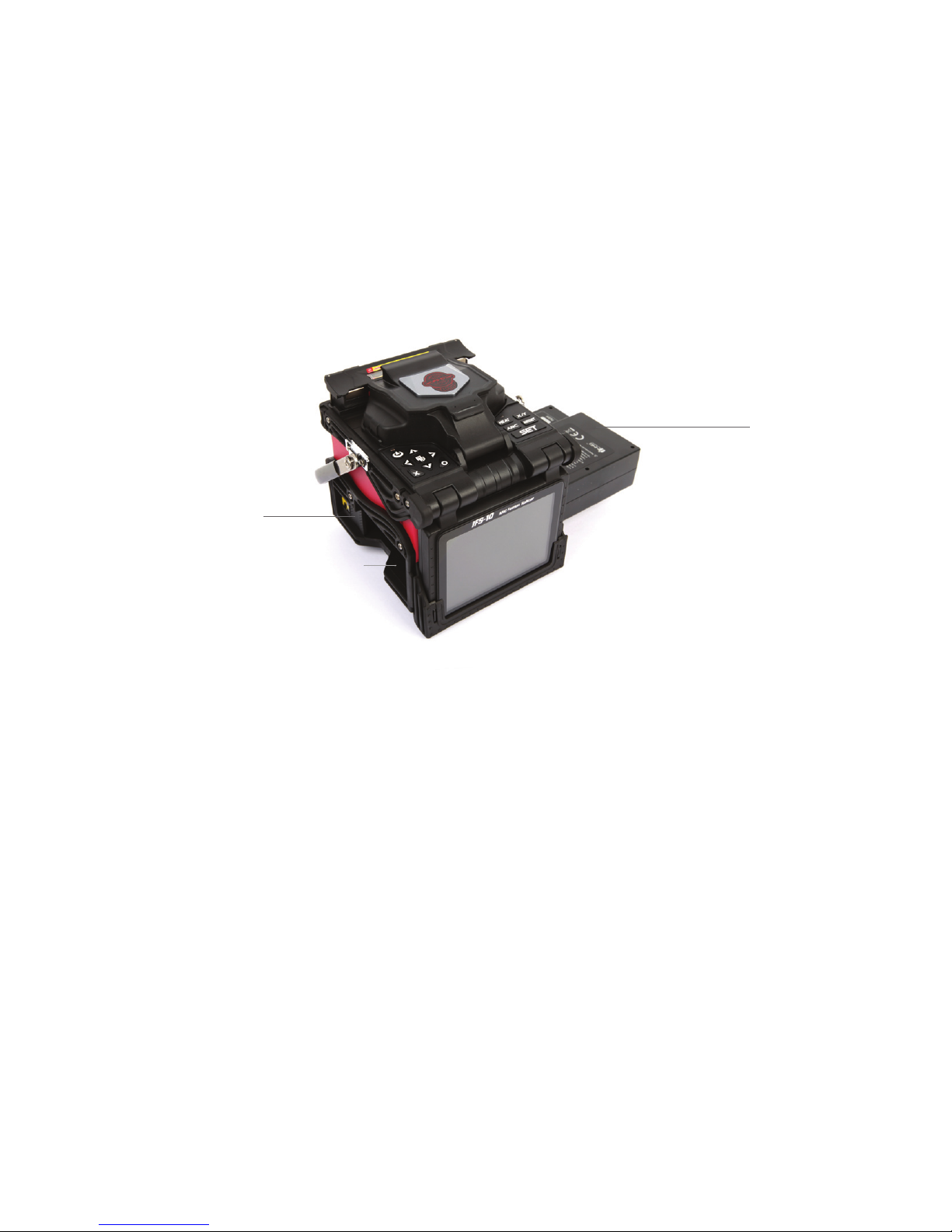
Overview of external parts
Heat oven
On / Off button
Control buttons
Display
USB Terminal
Serial port
Connector for charging battery
Safety shield
Power supply / Battery
Splicer handle
Chapter 1 Installation
13
Power connection
General
The splicer can be powered from the power supply connected to the main outlet,
or from the battery. In either case, the power source is mounted underneath the
splicer.
Mounting the power source
Battery charger
General
The battery charger connects to a main outlet through a standard power cable.
A green LED, located is lit when the power supply is in operation.
Insert the Battery unit into the power unit dock until it clicks into place.
Insert
Release button
Draw power supply module out
Chapter 1 Installation

14
Charging the battery
Charging progress is indicated by ve red LEDs continuously sweeping from 20%
to 100% on the battery indicator. As charging proceeds, one LED is lit when 20%
charged. When it’s fully charged, all ve LEDs are lit (i.e. 100%)
Battery indicator
It is available to charge the battery in three different ways. When the battery is
detached from the splicer, it can be charged with AC charger.
Chapter 1 Installation

15
Charging the battery
The splicer can be charged in two different ways (see step1 and 2 below). The
power source which is used to charge the splicer is indicated by a special icon on
the bottom right-hand corner of the monitor (see below) If the battery is connected
to the slicer, then its charging level appears. If the battery is being used to charge
the splicer by the power supply, the charging level will appear in green color.
However, if the charge level drops under 20%, then the light will appear in red.
5%
10%
30%
50%
70%
100%
Step 1 Step 2
Chapter 1 Installation

16
Heat oven
Heat oven - Lid open Cooling tray
Chapter 1 Installation

17
Basic Operation
Scope and purpose of the manual
This chapter contains the following basic information:
•Quick guide
•Preparing the splicer
•Preparing the ber
•How to make a splice
•How to check the splice strength
•How to protect the splice
Quick guide
2
•Preparing the splicer
•Connecting the power supply
•Cleaning V-grooves
•Cleaning electrodes
•Preparing the ber
•How to strip the ber
•How to clean the ber
•How to cleave the ber
•How to splice
•Inserting the bers
•Inspecting the bers
•Splicing
•How to protect the splice
•Moving the ber to the heat oven
•Shrinking
•Resetting the ber movement motors
18
18
18
18
18
19
19
20
21
21
21
22
22
23
24
24

18
Preparing the splicer
Connecting the power supply
•Connect the splicer to the main by inserting the power cable into the socket on
the left side of power supply of the splicer.
Note: If the splicer is powered with a fully charged battery, then the main power
supply is not necessary.
•Press the On / Off button on the side of the splicer unit on the top left of the
front panel. If the LED becomes green, then the power is on. Press and hold the
On / Off button until the LED ashes, then release the button and the splicer will
power off.
Cleaning V-grooves
•Clean V-grooves, if necessary (see chapter 4 “Maintenance”)
Replace electrodes
•Check and make sure there are no ber within the splicer and close the safety
shield.
•From the main menu press:
•In the replace electrodes, press: “Conrm” to replace the electrodes.
Preparing the ber
There are three basic preparatory steps to be completed before the bers can be
placed in the splicer:
•Stripping
•Cleaning
•Cleaving
Chapter 2 Basic operation

19
Note: Always remember to slip a heat-shrinkable sleeve onto either end of the
bers at the beginning of each ber preparations.
Important: Preparing the bers for splicing is one of the most important factors
in the splicing process and must be carried out with the utmost care to minimize
splice loss. Poorly cleaned and cleaved bers will normally result in high splice loss
and low mechanical strength.
How to strip the ber
•Remove at least 50mm of secondary coating (valid for both tight and loose tube
secondary coating) with an appropriate stripper (see A, and B).
•Remove approximately 30mm of primary coating with an appropriate stripper
(see C).
Important: Do not put extra stress on the bers by bending or crimping them. (see
illustrations of different strippers below.)
How to clean the ber
Clean bare bers with a tissue or a pair of cotton swabs soaked in propanol or
ethanol.
Important: From this point, you must be very careful with the bers to ensure
that they do not become dirty again. (for example, avoid putting them down on a
dusty working surface, or even waving them around in the air). Also check if the
V-grooves are clean, if not, wipe them clean.
Loose tube
secondary coating
Tight secondary coating Primary coating coating
1 2 3
Chapter 2 Basic operation
Other manuals for IFS-10
1
Table of contents
Other INNO Instrument Welding System manuals


Popular Welding System manuals by other brands


Hobart Welding Products
Hobart Welding Products AirForce 375 owner's manual

GF
GF MSA 330 instruction manual

Hakko Electronics
Hakko Electronics FX-888D instruction manual

Abicor Binzel
Abicor Binzel ABIPLAS WELD 100 W operating instructions

EWM
EWM Taurus 355 Basic TDM operating instructions

Thermal Dynamics
Thermal Dynamics PakMaster 100 XL plus operating manual


