Innodisk nanoSSD PCIe 3TE7 Series User manual

PCIe 3TE7 Series
Customer:
Customer
Part
Number:
Innodisk
Part
Number:
Innodisk
Model Name:
Date:
Innodisk
Approver
Customer
Approver

nanoSSD PCIe 3TE7
2Rev 1.7 TPS, Apr., 2022
Table fo contents
LIST OF FIGURES ........................................................................................................ 7
1. PRODUCT OVERVIEW .............................................................................................. 8
1.1 INTRODUCTION OF INNODISK NANOSSD PCIE 3TE7 ..................................................... 8
1.2 PRODUCT VIEW AND MODELS .................................................................................... 8
2. PRODUCT SPECIFICATIONS..................................................................................... 9
2.1 Capacity and Device Parameters ........................................................................ 9
2.2 PERFORMANCE ........................................................................................................ 9
2.3 Electrical Specifications .................................................................................... 10
2.3.1 Power Requirement .................................................................................... 10
2.3.2 Power Consumption.................................................................................... 10
2.4 ENVIRONMENTAL SPECIFICATIONS ........................................................................... 10
2.4.1 Temperature Ranges................................................................................... 10
2.4.2 Humidity ..................................................................................................... 11
2.4.3 Shock and Vibration.................................................................................... 11
2.4.4 Mean Time between Failures (MTBF) .......................................................... 11
2.5 ROHS COMPLIANCE ............................................................................................... 11
2.6 Reliability ......................................................................................................... 12
2.7 TRANSFER MODE ................................................................................................... 12
2.8 Ball and Signal Description ............................................................................... 13
2.9 Power Supply & Sequence ................................................................................ 17
2.10 Mechanical Dimensions .................................................................................. 18
2.11 Seek Time....................................................................................................... 18
2.12 NAND FLASH MEMORY ........................................................................................ 18
3. THEORY OF OPERATION ........................................................................................ 19
3.1 OVERVIEW .......................................................................................................... 19
3.2 ERROR DETECTION AND CORRECTION ........................................................................ 19
3.3 WEAR-LEVELING .................................................................................................. 19
3.4 BAD BLOCKS MANAGEMENT..................................................................................... 20
3.5 POWER CYCLING .................................................................................................. 20
3.6 GARBAGE COLLECTION ........................................................................................... 20
3.7 TRIM ................................................................................................................ 20
3.8 POWER MANAGEMENT............................................................................................ 20
4. INSTALLATION REQUIREMENTS ............................................................................ 21
4.1 REFERENCE DESIGN .............................................................................................. 21
4.2 PRODUCTION GUIDE.............................................................................................. 21
4.2.1 Preheat ....................................................................................................... 21
nanoSSD PCIe 3TE7
4Rev 1.7 TPS, Apr., 2022
REVISION HISTORY
Revision
Description
Date
Rev. 1.0
First Released
Sep., 2020
Rev. 1.1
Update MSL Declaration
Oct., 2020
Rev. 1.2
Update 512GB
Nov., 2020
Rev. 1.3
Remove AES and TCG Opal support
Jun., 2021
Rev. 1.4
Updates:
- pin layout drawing
- pin assignment for Y19
- device parameters (user capacity)
- mechanical dimensions 32GB-256GB, 512GB and
bottom view
- RoHS and REACH declaration
Jul., 2021
Rev. 1.5
Updates:
-performance
-feature list
-storage temperature
-power consumption
Remove:
RoHS, REACH and MSL
Jul., 2021
Rev 1.6
Update nanoSSD PCIe 3TE7 pin assignment for C10,
D10, and C6
Update block diagram
Mar., 2022
Rev 1.7
Update mechanical drawing and PN rule table
Apr., 2022

nanoSSD PCIe 3TE7
5Rev 1.7 TPS, Apr., 2022
Features: Power Requirements:
PCIe Gen.3 x 2
Industrial 3D TLC 64-layer NAND
Standard & Wide-temperature
Dynamic Thermal Management
Hybrid Write
Performance: Reliability:
Sequential Read up to 1,650 MB/s
Sequential Write up to 1,350 MB/s
*2years duration after 100% (3000) P/E cycles at 55℃
For warranty details, please refer to:
https://www.innodisk.com/en/support_and_service/warranty
Input Voltage
3.3V± 5%
Max Operating
Wattage
1.6W
Idle Wattage
0.4W
Capacity
[Client]
TBW
[Client]
DWPD
32GB
64GB
128GB
256GB
512GB
19
38
76
152
304
0.81
0.81
0.81
0.81
0.81
Data Retention
Years
Warranty
2 Years*

nanoSSD PCIe 3TE7
6Rev 1.7 TPS, Apr., 2022
List of Tables
TABLE 1: DEVICE PARAMETERS.....................................................................................................................................9
TABLE 2: PERFORMANCE ................................................................................................................................................9
TABLE 3: INNODISK NANOSSD PCIE 3TE7 POWER REQUIREMENT................................................................10
TABLE 4: POWER CONSUMPTION ...............................................................................................................................10
TABLE 5: TEMPERATURE RANGE FOR NANOSSD PCIE 3TE7.............................................................................10
TABLE 6: SHOCK/VIBRATION TESTING FOR NANOSSD PCIE 3TE7 ...............................................................11
TABLE 7: NANOSSD PCIE 3TE7 MTBF..................................................................................................................11
TABLE 8: INNODISK NANOSSD PCIE 3TE7 PIN ASSIGNMENT ........................................................................13

nanoSSD PCIe 3TE7
7Rev 1.7 TPS, Apr., 2022
List of Figures
FIGURE 1: INNODISK NANOSSD PCIE 3TE7 ..........................................................................................................8
FIGURE 2: INNODISK NANOSSD PCIE 3TE7 PIN LAYOUT ................................................................................16
FIGURE 3: INNODISK NANOSSD PCIE 3TE7 BLOCK DIAGRAM........................................................................19

nanoSSD PCIe 3TE7
8Rev 1.7 TPS, Apr., 2022
1. Product Overview
1.1 Introduction of Innodisk nanoSSD PCIe 3TE7
InnoDisk nanoSSD PCIe 3TE7 is an NVM Express storage device designed as the standard
11.5*13.0 mm2 ball grid array (BGA) package form factor with PCIe interface. The nanoSSD
supports PCIe Gen III x2 within a tiny dimension, and it is compliant with NVM 1.3 providing
excellent performance. Moreover, it adopts industrial 3D TLC NAND Flash providing high
endurance and reliability, as well as low power consumption and high reliability. It offers an ideal
solution for embedded, automotive, medical, gaming and most industrial applications.
CAUTION TRIM must be enabled.
TRIM enables SSD’s controller to skip invalid data instead of moving. It can free up significant amount of
resources, extends the lifespan of SSD by reducing erase, and write cycles on the SSD. Innodisk’s handling of
garbage collection along with TRIM command improves write performance on SSDs.
1.2 Product View and Models
Innodisk nanoSSD PCIe 3TE7 is available in follow capacities:
nanoSSD PCIe 3TE7 32GB nanoSSD PCIe 3TE7 64GB
nanoSSD PCIe 3TE7 128GB nanoSSD PCIe 3TE7 256GB
nanoSSD PCIe 3TE7 512GB
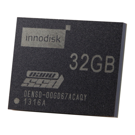
Figure 1: Innodisk nanoSSD PCIe 3TE7

nanoSSD PCIe 3TE7
9Rev 1.7 TPS, Apr., 2022
2. Product Specifications
2.1 Capacity and Device Parameters
nanoSSD PCIe 3TE7 device parameters are shown in Table 1.
Table 1: Device parameters
Capacity
LBA
User Capacity
(MB)
32GB
62533296
30533
64GB
125045424
61057
128GB
250069680
122104
256GB
500118192
244198
512GB
1000215216
488386
2.2 Performance
Burst Transfer Rate: 6.0Gbps
Table 2: Performance
Capacity
32GB
64GB
128GB
256GB
512GB
Sequential
Read (Max)
300 MB/s
600 MB/s
1,150 MB/s
1,600 MB/s
1,650 MB/s
Sequential
Write (Max)
130 MB/s
280 MB/s
550 MB/s
1,100 MB/s
1,350 MB/s
4KB Random
Read (QD32)
26,000
52,000
101,700
155,000
157,000
4KB Random
Write (QD32)
30,000
64,000
126,000
132,000
136,000
Note: * Performance is based on CrystalDiskMark 6.0.2 with file size 1000MB of Queue Depth 32

nanoSSD PCIe 3TE7
10 Rev 1.7 TPS, Apr., 2022
2.3 Electrical Specifications
2.3.1 Power Requirement
Table 3: Innodisk nanoSSD PCIe 3TE7 Power Requirement
Item
Symbol
Rating
Unit
Input voltage
VIN
+3.3 DC +- 5%
V
2.3.2 Power Consumption
Table 4: Power Consumption
Voltage Rail
Rating
Power Consumption (W)
Main power supply
3.3 V ± 5%
1.6
Flash IO supply
1.8 V ± 5%
0.3
Controller core supply
1.2 V ± 5%
0.6
* Target: nanoSSD PCIe 3TE7 512GB
2.4 Environmental Specifications
2.4.1 Temperature Ranges
Table 5: Temperature Range for nanoSSD PCIe 3TE7
Temperature
Range
Operating
Standard Grade: 0°C to +70°C
Industrial Grade: -40°C to +85°C
Storage
-40°C to +85°C
Below are some recommendations for PCB design to lowest effect of thermal.
Maximize copper thickness and trace width for all pins to thermal features such as thermal vias,
thermal side rails, and thermal conduction screw holes.
Copper ground/supply planes in the PCB can provide very effective heat dissipation for the IC
package. To maximize effectiveness, thermal vias should be added to connect the package’s
mechanical ground balls to the ground plane. There should be at least one thermal via
allocated for each MGB of the package. The plating thickness of vias should be maximized to
optimize thermal conduction.

nanoSSD PCIe 3TE7
11 Rev 1.7 TPS, Apr., 2022
2.4.2 Humidity
Relative Humidity: 10-95%, non-condensing
2.4.3 Shock and Vibration
Table 6: Shock/Vibration Testing for nanoSSD PCIe 3TE7
Reliability
Test Conditions
Reference Standards
Vibration
7 Hz to 2K Hz, 20G, 3 axes
IEC 68-2-6
Mechanical Shock
Duration: 0.5ms, 1500 G, 3 axes
IEC 68-2-27
2.4.4 Mean Time between Failures (MTBF)
Table 7 summarizes the MTBF prediction results for various nanoSSD PCIe 3TE7 configurations.
The analysis was performed using a RAM Commander™failure rate prediction.
‧Failure Rate: The total number of failures within an item population, divided by the total
number of life units expended by that population, during a particular measurement interval
under stated condition.
‧Mean Time between Failures (MTBF): A basic measure of reliability for repairable items:
The mean number of life units during which all parts of the item perform within their specified
limits, during a particular measurement interval under stated conditions.
Table 7: nanoSSD PCIe 3TE7 MTBF
Product
Condition
MTBF (Hours)
Innodisk nanoSSD PCIE 3TE7
Telcordia SR-332 GB, 25°C
>3,000,000
2.5 RoHS Compliance
nanoSSD PCIE 3TE7 is fully compliant with RoHS directive.

nanoSSD PCIe 3TE7
12 Rev 1.7 TPS, Apr., 2022
2.6 Reliability
Parameter
Value
Read Cycles
Unlimited Read Cycles
Flash endurance
3,000 P/E cycles
Wear-Leveling Algorithm
Support
Bad Blocks Management
Support
DIE RAID Recovery
Support
Error Correct Code
Support
TBW* (Total Bytes Written)
Capacity
Client workload
32GB
18.75
64GB
37.5
128GB
75
256GB
150
512GB
300
* Note:
Client: Follow JESD218 Test method and JESD219A Workload, tested by
ULINK. (The capacity lower than 64GB client workload is not specified in
JEDEC219A, the values are estimated.)
2.7 Transfer Mode
nanoSSD PCIe 3TE7 supports following transfer modes:
PCIe Gen III 8Gbps
PCIe Gen II 4Gbps
PCIe Gen I 2Gbps

nanoSSD PCIe 3TE7
13 Rev 1.7 TPS, Apr., 2022
2.8 Ball and Signal Description
The following table provides the pin definition of nanoSSD PCIe 3TE7 345-balls.
“P” and “N” in differential signals, e.g. PTXP1 and PTXN1, mean positive-end signal and
negative-end signal.
In signal names with “#”, e.g. PCLKREQ#, PRESET#, RESET# and JT_TRST#, the “#” means
“active low”.
Table 8: Innodisk nanoSSD PCIe 3TE7 Pin Assignment
Signal Name
Ball Number
Pin Type *
Description
PCIE_REFCLKP
AA4
I
PCIe
interface
PCIe Reference Clock P
PCIE_REFCLKN
AA5
I
PCIe Reference Clock N
PTXP1
AA16
O
PCIe Lane 1 Transmitter Differential Signal P
PTXN1
AA17
O
PCIe Lane 1 Transmitter Differential Signal N
PRXP1
Y13
I
PCIe Lane 1 Receiver Differential Signal P
PRXN1
Y14
I
PCIe Lane 1 Receiver Differential Signal N
PTXP0
Y10
O
PCIe Lane 0 Transmitter Differential Signal P
PTXN0
Y11
O
PCIe Lane 0 Transmitter Differential Signal N
PRXP0
Y7
I
PCIe Lane 0 Receiver Differential Signal P
PRXN0
Y8
I
PCIe Lane 0 Receiver Differential Signal N
PCLKREQ#
W3
I/O
PCIe Clock Request, Active Low
PRESET#
W4
I
PCIe Interface Hardware Reset, Active Low
XTAL_OUT
W18
O
Crystal
Crystal Output
XTAL_IN
W19
I
Crystal Input
RZQ_1
L2
N/A
ZQ
Memory or NAND calibration resistor
RZQ_2
L19
N/A
Memory or NAND calibration resistor
RESET#
B4
I
Reset
Power-on Reset, Active Low
TEST_MODE
D5
I
Test
ATE Test Mode Select
TP
B5
O
Analog Test Output

nanoSSD PCIe 3TE7
14 Rev 1.7 TPS, Apr., 2022
Signal Name
Ball Number
Pin Type *
Description
GP0
D4
I/O
Debug GPIO
(1.8V)
General Purpose Input and Output 0
GP1
C4
I/O
General Purpose Input and Output 1
GP2
C5
I/O
General Purpose Input and Output 2
GP3
C12
I/O
General Purpose Input and Output 3
GP4/LED_1#
Y2
I/O
General Purpose Input and Output 4 / Signal
output to drive an external transistor to
provide status indication via LED device
(Output, Active Low)
SDA/SMB_DATA
C11
I/O
I2C/SMBus
(1.8V)
I2C Data / SMBus Data - Open Drain
SCL/SMB_CLK
D11
I/O
I2C Clock / SMBus Clock - Open Drain
UTX/UAO
C13
O
UART
(1.8V)
UART Transmitter / UART Output
URX/UAI
D12
I
UART Receiver / UART Input
JT_TMS
C14
I
JTAG
(1.8V)
JTAG Mode Select
JT_TDI
C15
I
JTAG Data Input
JT_TRST#
D13
I
JTAG Reset, Active Low
JT_TDO
D14
O
JTAG Data Output
JT_TCK
D15
I
JTAG Clock
VCC
H2, H3, H18,
H19, J2,
J3, J18, J19,
K3, K18
Power (3.3V)
External Power Supply
VCCQ
D2, D3, D18,
D19, E2, E3,
E18, E19, F2,
F3,F18, F19,
T3, U3
Power (1.2/1.8V)
External Power Supply
VDDI
M3, M18, N2,
N3, N18,N19,
P2, P3, P18,
Power (1.2V)
Power Supply for internal LDO

nanoSSD PCIe 3TE7
15 Rev 1.7 TPS, Apr., 2022
P19
VDD
B6
Power (0.9V)
LDO Output - Core Power
1V8
T2, T18, T19,
U2, U18,U19
Power (1.8V)
Power for PCIe/PLL/Digital Input and Output,
Power Supplier Used by ATE
Signal Name
Ball Number
Pin Type *
Description
GND
A1, A2, A3, A6, A9, A12, A15, A18, A19, A20, AA1,
AA2, AA3, AA6, AA9, AA12, AA15, AA18, AA19,
AA20, AB1, AB2, AB3, AB6, AB9, AB12, AB15,
AB18, AB19, AB20, B1, B2, B3, B9, B12, B15, B19,
B20, C1, C2, C3, C18, C19, C20, E1, E4, E17, E20,
F4, F17, G2, G3, G4, G18, G19, H1, H17, H20, J4,
K2, K17, K19, L1, L3, L4, L18, L20, M1, M2, M17,
M19, M20, N4, P17, R1, R2, R3, R4, R18, R19, R20,
T17, U4, U17, V1, V2, V3, V4, V17, V18, V19, V20,
W5, W6, W7, W8, W9, W10, W11, W12, W13, W14,
W15, Y1, Y3, Y4, Y5, Y6, Y9, Y12, Y15, Y16, Y17,
Y18, Y20
Ground
Ground
HSB
E5, E6, E7, E8, E9, E10, E11, E12, E13, E14, E15,
E16, F5, F6, F7, F8, F9, F10, F11, F12, F13, F14,
F15, F16, G5, G6, G7, G8, G9, G10, G11, G12, G13,
G14, G15, G16, G17, H4, H5, H6, H7, H15, H16, J5,
J6, J8, J9, J10, J11, J12, J13, J15, J16, J17, K4, K5,
K6, K8, K13, K15, K16, L5, L6, L8, L13, L15, L16,
L17, M4, M5, M6, M8, M13, M15, M16, N5, N6, N8,
N13, N15, N16, N17, P4, P5, P6, P8, P9, P10, P11,
P12, P13, P15, P16, R5, R6, R15, R16, R17, T4, T5,
T6, T7, T8, T9, T10, T11, T12, T13, T14, T15, T16,
U5, U6, U7, U8, U9, U10, U11, U12, U13, U14, U15,
U16, V5, V6, V7, V8, V9, V10, V11, V12, V13, V14,
V15, V16
NC
Host specific balls
RFU
C7, C8, C9, D6, D7, D8, D9, D16, W16
NC
Reserved for future use
NC
B16, B17, B18, C6, C10, C16, C17, D10, D17, W2,
W17, Y19
NC
Not Connect
*Note: I - Input Only, O - Output Only, I/O - Input and Output

nanoSSD PCIe 3TE7
16 Rev 1.7 TPS, Apr., 2022
Figure 2: Innodisk nanoSSD PCIe 3TE7 Pin Layout

nanoSSD PCIe 3TE7
17 Rev 1.7 TPS, Apr., 2022
2.9 Power Supply & Sequence
Input voltage
Voltage Rail
Specification
VCC
3.3V± 10%
VCCQ
1.8V ± 5%
VDDI
1.2V ± 5%

nanoSSD PCIe 3TE7
18 Rev 1.7 TPS, Apr., 2022
2.10 Mechanical Dimensions
Bottom View (345-ball)
2.11 Seek Time
Innodisk nanoSSD PCIe 3TE7 is not a magnetic rotating design. There is no seek or rotational
latency required.
2.12 NAND Flash Memory
Innodisk nanoSSD PCIe 3TE7 uses 3D TLC NAND flash memory, with 3,000 program & erase cycles,
which is non-volatility, high reliability and high-speed memory storage.

nanoSSD PCIe 3TE7
19 Rev 1.7 TPS, Apr., 2022
3. Theory of Operation
3.1 Overview
Figure 2 shows the operation of Innodisk nanoSSD PCIe 3TE7 from the system level, including the
major hardware blocks.
Figure 3: Innodisk nanoSSD PCIe 3TE7 Block Diagram
Innodisk nanoSSD PCIe 3TE7 integrates a PCIe Gen 3x2 controller and NAND flash memories.
When connected with a host, the nanoSSD uses the integrated controller with four NAND channels
x 4 native CE and PCIe Gen3 x2 interface to manage the embedded NAND flash array consisting of
either 1/2/4/8/16 NAND dies
3.2 Error Detection and Correction
Innodisk nanoSSD PCIe 3TE7 is designed with hardware LDPC ECC engine with hard-decision and
Soft-decision decoding. Low-density parity-check (LDPC) codes have excellent error correcting
performance close to the Shannon limit when decoded with the belief-propagation (BP) algorithm
using soft-decision information.
3.3 Wear-Leveling
Flash memory can be erased within a limited number of times. This number is called the erase
cycle limit or write endurance limit and is defined by the flash array vendor. The erase cycle
limit applies to each individual erase block in the flash device.
Innodisk nanoSSD PCIe 3TE7 uses a static wear-leveling algorithm to ensure that consecutive
writes of a specific sector are not written physically to the same page/block in the flash. This
spreads flash media usage evenly across all pages, thereby extending flash lifetime.

nanoSSD PCIe 3TE7
20 Rev 1.7 TPS, Apr., 2022
3.4 Bad Blocks Management
Bad Blocks are blocks that contain one or more invalid bits whose reliability are not guaranteed.
The Bad Blocks may be presented while the SSD is shipped, or may develop during the life time of
the SSD. When the Bad Blocks is detected, it will be flagged, and not be used anymore. The SSD
implement Bad Blocks management, Bad Blocks replacement, Error Correct Code to avoid data
error occurred. The functions will be enabled automatically to transfer data from Bad Blocks to
spare blocks, and correct error bit.
3.5 Power Cycling
Innodisk’s power cycling management is a comprehensive data protection mechanism that
functions before and after a sudden power outage to SSD. Low-power detection terminates data
writing before an abnormal power-off, while table-remapping after power-on deletes corrupt data
and maintains data integrity. Innodisk’s power cycling provides effective power cycling
management, preventing data stored in flash from degrading with use.
3.6 Garbage Collection
Garbage collection technology is used to maintain data consistency and perform continual data
cleansing on SSDs. It runs as a background process, freeing up valuable controller resources while
sorting good data into available blocks, and deleting bad blocks. It also significantly reduces write
operations to the drive, thereby increasing the SSD’s speed and lifespan.
3.7 TRIM
The TRIM command is designed to enable the operating system to notify the SSD which pages no
longer contain valid data due to erases either by the user or operating system itself. During a
delete operation, the OS will mark the sectors as free for new data and send a TRIM command to
the SSD to mark them as not containing valid data. After that the SSD knows not to preserve the
contents of the block when writing a page, resulting in less write amplification with fewer writes to
the flash, higher write speed, and increased drive life.
3.8 Power Management
- Support multi-level power states: PS0, PS1, PS2, PS3, PS4
- Support thermal throttling with configurable temperature threshold.
Table of contents
Other Innodisk Storage manuals

Innodisk
Innodisk InnoAGE 2.5" SATA SSD 3TI7 User manual

Innodisk
Innodisk 3ME Series User manual

Innodisk
Innodisk 3SR-P Series User manual

Innodisk
Innodisk nanoSSD Series Guide

Innodisk
Innodisk SATADOM-MV 3ME3 Series User manual

Innodisk
Innodisk 3MG-P Series User manual

Innodisk
Innodisk 3SE-P Series User manual

Innodisk
Innodisk 3TS6-P Series User manual

Innodisk
Innodisk 3MR2-P 8GB User manual

Innodisk
Innodisk 3TR6-P Series User manual