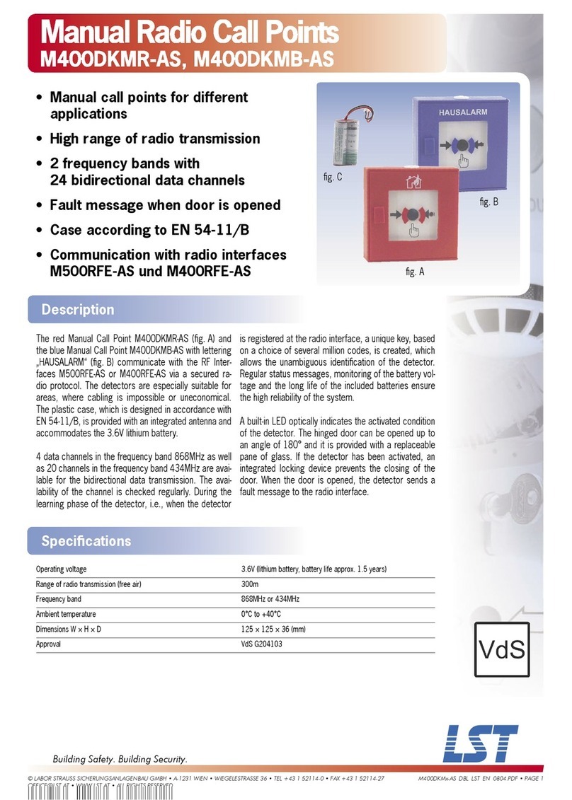
Innohome SGK4030 User manual

For indoor use only.
Do not use in a professional kitchen.
The Control Unit must be installed by
an authorised electrician.
REFERENCE AND
INSTALLATION
MANUAL
INSTALLATION P. 4–13 USER GUIDE P. 14–21 TECHNICAL SPECIFICATIONS
P. 22–24
1 2
INNOHOME
STOVE GUARD
SGK4030
3
770-00041-A2

Thank you for choosing Innohome Stove Guard!
Safety rules
Stove Guard does not prevent all potentially dangerous situations, but it makes the use of the cooker signicantly safer.
Never leave the cooker unattended. Always check compliance with local regulations.
• For indoor use only.
• Do not use in a professional kitchen.
• Do not hold the Heat Sensor close to the ear. It can
cause hearing damage when in alarm or test mode.
• Do not leave children alone with the product or any
of its parts or packaging. There is a risk of choking.
• Do not disassemble the product.
• Do not immerse the Heat Sensor in water.
• The Stove Guard will not emit an alarm if the tem-
perature of the cooker is too low to identify a dan-
gerous situation, or if the cooker has an automatic
limitation of temperature increase.
• The Stove Guard will not completely isolate
the cooker. It must never be used to turn o the
cooker's power supply for service/repair.
• Do not short-circuit, charge, open or heat the
batteries. There is a risk of explosion.
The operating instructions, accessories and stickers must accompany the product. Follow the safety guidance for safe
use of Stove Guard. If you have questions about the product, ask a specialist or refer to innohome.com
Innohome Stove Guard is a safety product for domestic kitchens. The Stove
Guard consists of a state-of-the-art Heat Sensor that monitors the cooker from
the top, and a Control Unit that cuts the power if a dangerous situation occurs.
The Control Unit is installed behind the cooker or inside the kitchen cabinet next
to the cooker. Ensure to read this manual prior to commencing installation.
SALES PACKAGE CONTENTS:
• Heat Sensor SGS1030
• Battery (CR2032)
• IR lens extension
• Control Unit SGC430-1U3-50
• Main manual
• Cupboard sticker
2
INSTALLATION 4–13
Installation of the Heat Sensor 5
Installation of the Control Unit 12
Function test 13
CONTENTS
1
2
3
1a
Installation under cooker hood
1b Wall mounting
1c
Ceiling mounting
USER GUIDE 14–21
Getting started with Innohome Stove Guard 15
Read before using Innohome Stove Guard 16–17
Avoiding false alarms 16
After alarm: Cookers with mechanical controls 16
After alarm: Cookers with touch controls 16
Dislocation alarm 16
Action in the event of an alarm 17
Other settings 18–19
Changing the sensitivity level 18
Checking the sensitivity level 19
Resetting the Heat Sensor to factory settings 19
Pairing devices 19
Frequently asked questions 20–21
TECHNICAL SPECIFICATIONS 22–24
The Stove Guard 22
Warranty 23
Disposal 23
Applied standards 23
P. 6 -7 P. 8-9 P.10-11
RECOMMENDED
OPTIONAL
3

INSTALLATION
1
Installing the Stove Guard
To install correctly, follow the instructions.
STEP 1:
Installation of
the Heat Sensor
p. 5-11
STEP 2:
Installation of
the Control Unit
p. 12
STEP 3:
Function test
p. 13

INSTALLATION
OF THE HEAT SENSOR
The recommended place to install the Heat Sensor is directly above the centre
of the cooker, under the cooker hood. The Heat Sensor can also be mounted on
a wall with a mounting bracket or on the ceiling. Follow these instructions for
correct installation.
Installation plate
with adhesive tape
Heat Sensor
Optional IR lens
extension (black)
INSTALLATION LOCATIONS
1a
Installation under cooker hood
1b Wall mounting
1c Ceiling mounting
RECOMMENDED OPTIONAL
Mounting bracket SAI1000-FBS
required for wall installations
- available separately.
For ceiling installations,
the supplied IR lens
exten-
sion must also be tted.
See page 10.
5

15cm
COOKER
HOOD
Select the mounting location
Measure the installation height. The Heat Sensor should be centred
above the cooker, preferably within Zone 1 (see the diagram below).
It can be attached to the grease lter. It is important to ensure the
minimum distance from the light underneath the hood is 4" (10cm)
(2" (5cm) is enough for LED lamp).
Zone 1 is recommended for best performance.
Mount the Heat Sensor
The Heat Sensor might beep at
this stage indicating that it is not
properly placed on the installa-
tion plate. As this happens, no
further action is required.
If there is a metal mesh grease
lter on the cooker hood, make
sure it is greaseless and dry. Press
at least for a minute from the
opposite side while attaching
adhesive.
Carefully remove the protective
lm from the installation plate.
Attach the Heat Sensor with the
LED facing the user.
Attach the installation plate
while the Heat Sensor is on it.
1 2
1a
Zone 2 Zone 1
Radius 6"
(15cm)
Min 4" (10cm)
Min 2" (5cm)
for LED lamp
Zone 1 is immediately
above the middle of the
cooker plates. Max 6"
(15cm) from the centre.
INSTALLATION
Zone 1
6

INSTALLATION UNDER
COOKER HOOD
Allow the Heat Sensor to reach room temperature before use. The power
to the cooker must be switched o (at the consumer unit). See the table
below for the mounting location and follow instructions 1–4.
Starting the Heat Sensor
Insert the battery and place the
Heat Sensor on the installation
plate.
Press the button shortly.
(LED ashes green).
Check installation height
If the distance from cooker to Heat Sensor is more than 24" (60cm), the
Heat Sensor's sensitivity level must be adjusted manually.
Please refer to the table underneath together with the information on
page 18, alternatively watch the lm on sensitivity conguration.
3 4
7
DISTANCE FROM COOKER
TO HEAT SENSOR
MOUNTING LOCATION SENSITIVITY LEVEL CONFIGURATION
0"–24" (0–60cm)
wide cooker
25"–36" (61–90cm)
wide cooker
Sensitivity Acknowledgement "beep(s)"
33"–40" (81–100cm) Zone 1 & Zone 2 Zone 1 3 presses
31"–32" (76–80cm)
Zone 1
Zone 2*
Zone 1*
4 presses
29"–30" (71–75cm) 5 presses
27"–28" (65–70cm) 6 presses
25"–26" (61–64cm) 7 presses
18"–24" (45–60cm)
Factory setting
8 presses
* The installation may not in all cases meet all EN standard requirements.
See FAQ, page 22, point 4
Please note: the sensitivity level of the Heat Sensor is
conrmed by the appropriate sound pattern sequence
only and not the LED ashes.
Watch the lm:
https://vimeo.com/321503955
Setting sensitivity
Watch the lm:
https://vimeo.com/321502592
Sensor installation

Select the required location and mount the bracket
Wall mounting requires a bracket (SAI1000-FBS), sold separately. The
bracket is fastened on the wall using adhesive tape or screws.
See the mounting instructions in the bracket package. Make sure that
the bracket is positioned correctly so that the Heat Sensor faces towards
the centre of the cooker.
Mount the Heat Sensor
The Heat Sensor might beep at
this stage indicating that it is not
properly placed on the installa-
tion plate. As this happens, no
further action is required.
Press at least for a minute while
attaching adhesive.
Carefully remove the protective
lm from the installation plate.
Attach the Heat Sensor with the
LED facing the user.
Attach the installation plate
while the Heat Sensor is on it.
2b
21
Mounting height on the wall above the cooker
Max 36" (90cm) wide cooker.
Recommended: 32" (80cm)
Alternatively: 26"–31" * (65–79cm)
See mounting instructions provided separately with the bracket.
* For wall mounting with a distance less than 32" (80cm) between the
Heat Sensor and the cooker, the installation will not in all cases meet all
EN standard requirements.
INSTALLATION
1b WALL
3
8

WALL MOUNTING
WITH BRACKET
Allow the Heat Sensor to reach room temperature before use. The power to the
cooker must be switched o (at the consumer unit). See the table below for
the mounting location and follow instructions 1–5.
Starting the Heat Sensor
Insert the battery and place the
Heat Sensor on the installation
plate.
Press the button shortly.
(LED ashes green).
Set the sensitivity level
Set the Heat Sensor's sensitivity level according to the mounting height
(as described in the table) by evenly pressing the Sensor's button.
Please refer to the table underneath together with the information on
page 18, alternatively watch the lm on sensitivity conguration.
DISTANCE FROM COOKER TO HEAT SENSOR
SENSITIVITY LEVEL CONFIGURATION
Sensitivity Acknowledgement “beep(s)”
28"–32" (70–80cm) *3 presses
26"–27" (65–69cm) *4 presses
* 32" (60cm) recommended. For wall mounting with a distance less than 32" (60cm)
between the Heat Sensor and the cooker, the installation will not in all cases meet
all EN standard requirements.
Please note: the sensitivity level of the Sensor is conrmed by the
appropriate sound pattern sequence only and not the LED ashes.
4 5
9
Watch the lm:
https://vimeo.com/321503955
Setting sensitivity
Watch the lm:
https://vimeo.com/321502592
Sensor installation

Replace lens
Carefully lift the lens with a
screwdriver. Press down the
IR lens extension (included)
as shown in the picture. The
extension should point directly
upwards at an angle of 90°. If the
extension moves around, check
that it has been inserted
the right way round.
Finding the mounting
position
Measure the distance between
the cooker and ceiling. Place the
Heat Sensor directly above the
center point of the cooker. Make
sure that the surface is clean
and dry.
Mount the Heat Sensor
The Heat Sensor might beep at
this stage indicating that it is not
properly placed on the installa-
tion plate. As this happens, no
further action is required.
Make sure that ceiling is grease-
less and dry. Press at least for a
minute while attaching adhesive.
Carefully remove the protective
lm from the installation plate.
Attach the Heat Sensor with the
LED facing the user.
Attach the installation plate
while the Heat Sensor is on it.
CEILING
1 2
INSTALLATION
1c
3
10

Allow the Heat Sensor to reach room temperature before use. The power
to the cooker must be switched o (at the consumer unit). See the table
below for the mounting location and follow instructions 1–5.
Starting the Sensor
Insert the battery and place the
Heat Sensor on the installation
plate. Press the button shortly.
(LED ashes green).
Set sensitivity level
Set the sensitivity level according to the mounting height (as described
in the table) by evenly pressing the Sensor's button. The Heat Sensor's
sensitivity level must be always adjusted when installing it to the ceiling.
Please refer to the table underneath together with the information on page
18, alternatively watch the lm on sensitivity conguration).
DISTANCE FROM COOKER TO HEAT SENSOR
SENSITIVITY LEVEL CONFIGURATION
Mounting height above the
cooker
0–36" (0–90cm) wide cooker Sensitivity Number of
"beep(s)"
64"–80" (160–200cm) Recommended: Immediately above
the middle of the cooker.
Alternatively: Farther out into the
room with bracket. See the bracket
package for mounting instructions.
1 press
2 presses
Mounting height above the
cooker
0–36" (0–90cm) wide cooker
56"–63" (140–159cm) Recommended: Immediately above
the middle of the cooker.
Alternatively: Farther out into the
room with bracket. See the bracket
package for mounting instructions.
Please note: the sensitivity level of the Sensor is conrmed by the appropriate sound pattern sequence only and not the LED ashes.
CEILING MOUNTING
WITH IR LENS EXTENSION
3 4
11
Watch the lm:
https://vimeo.com/321503955
Setting sensitivity
Watch the lm:
https://vimeo.com/321502592
Sensor installation

It is a statutory requirement that the Control Unit is installed by an authorized
electrician. The power to the cooker must be disconnected throughout the entire
installation.
Disconnect the power
Switch o the power at the
consumer unit.
Note! Do not turn on the
Consumer unit before the Heat
Sensor is set and ready for a
function test.
Connect to the Control Unit
• Unplug the cooker.
• Connect the cooker to the Control Unit.
• Plug the input cord of the Control Unit
to the cooker wall outlet.
CONTROL UNIT
1
INSTALLATION
POWER
OFF 2
12

The installation is completed when the test has been passed.
The Heat Sensor will then give an alarm. This user manual, accessories
and stickers should be left with the product for future reference.
Return the power
Switch on the power at the
consumer unit.
Perform function test
Wait 30 seconds after switching
on the power. Press and hold
the button until the Heat Sensor
emits a “beep” ( ) and the red
LED ashes. Release the hold.
The Control Unit will switch o
the cooker and give an alarm
signal every 5 seconds. The Heat
Sensor will also emit a test alarm
after a few seconds.
Note! Check that there is no
power going to the cooker.
Reset the alarm
It is important to reset the alarm
after a function test to ensure
power to the cooker. Reset the
test alarm by pressing the button
once.
Check that the cooker can be
turned on (or that there is
voltage in the Control Unit).
If the Heat Sensor does not
respond or if the test alarm
cannot be reset, see page 20,
points 5 and 6.
FUNCTION TEST
1 2 3
Installation is now ready.
When connecting the Stove Guard for the rst time it is advisable to wait 15 minutes before normal
cooker use to allow the Stove Guard to perform nal system checks.
POWER
ON
13
Watch the lm:
https://vimeo.com/321504308
Test alarm

2USER
GUIDE

The cooker is ready for use 15 minutes after completing the installation
of the Stove Guard. However, at the beginning, it may start to signal
during normal cooking. This is because the Heat Sensor learns what
the normal temperature ranges are during cooking.
GETTING STARTED
The Heat Sensor may start
making short“beeps” every ve
seconds while it is being used
(“pre-alarm”).
Press the button to indicate that
it is not a dangerous situation.
The Heat Sensor has then learned
more about your cooking habits
and you can continue cooking.
Please note:
When installing the Heat Sensor on the ceiling, the learning function will not be operational. The Heat
Sensor will automatically sound and switch the cooker o in the event of an increased heat condition.
The Heat Sensor learns and adjusts, when the user resets the pre-alarm. See FAQ page 21, point 14.
In order to reset the system, turn all controls o. The Stove Guard will automatically reset itself after
the heat condition has cleared and the cooker cooled.
15

READ BEFORE
Avoiding false alarms
Use a pan that covers the entire hotplate to prevent
false alarms. Using a lid is recommended.
Always use the cooker hood if you have one.
If you have a freestanding cooker or an oven under
the hob, the oven controls must also be turned o
once the power supply to the cooker or hob has been
switched o by the alarm.
After alarm
Mechanical controls
If the Stove Guard has turned the cooker o, rst turn
all cooker controls to ‘0’, then press the Heat Sensor
button once. After this, the cooker can be used nor-
mally. With ceiling installation, reset button is needed
to return the power.
Touch controls
If the Stove Guard has turned the cooker o, press the
Heat Sensor button once. After this, the cooker can
be used normally.
In some cases you must wait until the cooker has
cooled down to continue to use.
Dislocation alarm
Removing the Heat Sensor from the installation plate
cuts o the power to the cooker. Returning the
Sensor back to the installation plate returns the
power to the cooker. Press the Heat Sensor button
once.
USER GUIDE
16

SOUND MEANING MEASURES
Heat Sensor
4 “beeps”with a 1-second
interval.
Dislocation Alarm
The Heat Sensor is
removed from the
installation plate.
Return the Heat Sensor to the installation plate with the
LED facing the user.
Heat Sensor
Short “beeps” with
5-second intervals.
...
Pre-Alarm
The Heat Sensor sounds
an alert to danger
before
disconnecting the cooker.
If the alarm was triggered during normal cooking:
press the Heat Sensor button once while the pre-alarm
sounds. The alarm is turned o and the sensitivity
adjusts slightly.
Heat Sensor
Many quick “beeps” followed
by a long, very loud sound.
... !!!!
Switch-o Alarm
The cooker is switched
o.
Make sure that the controls are set to “0”. Press the Heat
Sensor button once to return the power to the cooker.
Control Unit
Short “ring”with 5-second
intervals.
No power
The power to the
cooker has been cut o.
Make sure that the controls are set to "0". Wait until the
cooker has cooled down after it has been disconnected
then press the Heat Sensor button once to return the
power. If the cooker cannot be switched back on, see
FAQ, question 9, page 21.
Control Unit
Continuous "rings".
No power
The cooker is too hot for
the power to be turned
back on.
Make sure that the controls are set to "0". Wait until the
cooker has cooled down and the Control Unit starts emit-
ting a short "ring" with 5-second intervals as described
in the section above, or press the Heat Sensor button
once to reconnect the cooker. If the alarm does not stop,
follow the instructions on page 21, FAQ question 9, and
press again.
Control Unit
Short and long “ring”with
10-second intervals.
No power due to
Auto-diagnostics
Alarm
The cooker has been
disconnected due to a
temporary fault (auto-
matic error diagnosis).
Make sure that the controls are set to "0". Wait until the
cooker has cooled down after it has been disconnected
then press the Heat Sensor button once to return the
power. If the cooker cannot be switched back on, see
FAQ, question 3, page 20.
Heat Sensor
One “beep” per minute.
Or
Control Unit
One “ring” per minute.
Battery Alarm
The Heat Sensor has a
low battery.
The Heat Sensor battery is low and needs to be replaced.
Pressing the button once at this time delays the alarm
for at least 12 hours.
Action in the event of an alarm
The cooker will automatically be ready for use after the Stove Guard has detected that the hazardous
situation is over, and all the controls are set to “0”. See the alarm overview below for actions.
17

Change the sensitivity level
Due to dierences in kitchen environments, the sensitivity level of the
Heat Sensor may have to be set manually.
1. Remove the Sensor from the installation plate
The Heat Sensor emits 4 “beeps” ( ). The cooker is turned o.
2. Adjust the sensitivity level
See pages 7–11 for sensivitity levels to be applied.
Place the Heat Sensor on the table (as shown in the picture). Press and hold in the button until 2 “beeps” ( )
are heard. Release the hold. The correct sensitivity can now be applied.
Note: When selecting the correct sensitivity level it is important the process is not rushed. Ensure the sensor
button is pressed rmly down each time, holding for a period of 1 second before releasing.
Ensure to pause for 1 second between each press.
3. Conrmation of setting
After 5–15 seconds, the Heat Sensor will conrm the sensitivity setting with the same number of “beeps”.
In case of error, start from step 2 again. Please note that the sensitivity level is conrmed by the appropriate
number of "beeps" only and not the LED ashes.
4. Activate the Sensor
Return the Heat Sensor correctly onto the installation plate. Press the button once.
USER GUIDE
OTHER SETTINGS
“BEEP” .... “BEEP”
18
Watch the lm:
https://vimeo.com/321503955
Setting sensitivity

Checking the
sensitivity level
1. Remove the Sensor from the
installation plate. (The Sensor
gives 4 “beeps” ( ) and the
cooker is switched o.)
2. Press and hold the button
(approx. 10 sec.) until 2 “beeps”
( ) are heard.
3. An unadjusted Sensor’s sensi-
tivity setting is level 8, and when
checking the level, the Sensor
gives a set of“beeps” as follows:
8 - 8 - 5 - 8. If the sensitivity was
adjusted to level 4, the sensor
would give“beeps”: 4 - 4 - 5 - 4.
Reset the Heat Sensor
to factory settings
Remove the Sensor from the
installation plate. (The Sensor gives
4 “beeps” ( ) power is cut o
to the cooker).
1. Remove the battery lid.
2. Press the button once.
3. Return the battery lid. The Heat
Sensor shall make a "beep".
4. Press and hold the button until
the three "beeps" are heard.
Release.
If three "beeps" cannot be heard,
something went wrong. Repeat
from Step 1. Return the Heat Sensor
to its installation plate and press the
button once.
“BEEP”“BEEP”“BEEP”
1
2
3
4
“BEEP”“BEEP”
19
Note! The Heat Sensor must be
placed on the mounting plate
during pairing.
1. Switch o the power for 15
seconds and switch it back on.
2. Within one minute from the
power reset, sweep the side of
Control Unit with the bottom
magnet of the mounting plate
so that the Control Unit makes
a buzzing sound. The Control
Unit is now ready to be paired.
3. Press and hold the button of
the NEW Heat Sensor until
it emits a “beep” and a red
LED ashes. The Control Unit
makes now a buzzing sound.
4. After 5 seconds, the Heat
Sensor gives an alarm (rst
one "beep" and after a while
continuous beeping).
The Control Unit and the Heat
Sensor are now successfully
paired.
5. Reset the test alarm by press-
ing shortly the Heat Sensor
button. Check that the cooker
can be turned on. If the Heat
Sensor does not respond or
if the test alarm cannot be
reset, rst repeatthe pairing
procedure
and then see FAQ,
page 22, points 5 and 6.
Pairing devices
The units are already paired at the factory.
When replacing the Heat Sensor or the
Control Unit, the devices must be paired again.
Watch the lm:
https://vimeo.com/321504101
Checking sensitivity
Watch the lm:
https://vimeo.com/321504446
Factory settings

1. I cannot turn on the cooker, and there is no
signal from the Control Unit.
ANSWER 1: The Heat Sensor has been removed or
placed
incorrectly on the installation plate. The Heat
Sensor shall be positioned parallel to the installation
plate and it is recommended to have LED facing to the
user.
ANSWER 2: If the Heat Sensor is correctly positioned
on the installation plate, the Control Unit’s overheat-
ing protection has switched the cooker’s power o.
The cooker can be switched on again by turning o
the power supply for a few seconds using the cook-
er’s fuse (in the consumer unit). If the overheating
protection fails again, move the Control Unit to a
cooler or better-ventilated place.
2. The Stove Guard emits alarms during normal
cooking.
ANSWER 1: As the Heat Sensor is positioned lower than
36" (90cm) above the cooker, it has a learning func-
tion (see page 15). Pressing the Heat Sensor button
during the pre-alarm lowers the sensitivity slightly.
Other causes of alarms during normal cooking:
• A pot is removed from a hot hotplate
• A kettle/pot does not cover the hotplate
• Cooking without a lid
• A hot frying pan placed on the hotplate
ANSWER 2: If measures to prevent unnecessary alarms
have been performed a few times and the Heat
Sensor still emits alarms in the same situation, the
sensitivity should be adjusted less sensitive manually,
for example from level 4 to level 5. See page 18.
3. The Auto-diagnostics alarm was not reset by
pressing the Heat Sensor button once.
ANSWER 1: The Auto-diagnostics alarm (Control
Unit emits one short and one long "ring" every ten
seconds) may be triggered if the Heat Sensor is not
on the installation plate, if it is positioned incorrect-
ly, or if it is covered by dirt or grease. It can also be
triggered by a problem with the radio connection or
malfunction of the Control Unit.
ANSWER 2: Make sure that the Heat Sensor is rmly
attached to the installation plate and that it is posi-
tioned correctly. The LED shall be facing the user (see
page 5). Clean the Heat Sensor with a lint-free cloth
moistened with soapy water. Press the Heat Sensor
button once.
ANSWER 3: Turn o the cooker’s power from the
consumer unit for 15 seconds.
ANSWER 4: If the fault diagnosis switches o the
cooker again, contact the retailer. If the cooker is still
turned o due to the fault diagnosis, it can only be
used for 5 minutes at a time by turning the power o
for 15 seconds as described in answer 2 above (EN
requirements).
4. Placing of the Heat Sensor in zones that do not
necessarily match all EN standard requirements.
ANSWER: According to the EN standard, the Heat
Sensor should "see" the base of the pot in order to
measure the temperature. In these zones (see the
tables on pages 7,9 and 11), the Heat Sensor cannot
see the bottom
of pots with high edges and may
identify a hazardous
situation somewhat more slow-
ly, but is still safe to use.
5. During the function test, the Heat Sensor does
not emit a sound when the button is pressed.
ANSWER: Make sure that the battery has power and
is inserted properly, "plus-side" up.
6. The test alarm cannot be reset.
ANSWER: First try the function test, see page 13. If this
does not x the problem, turn o the cooker’s power
at the consumer unit for 15 seconds and repeat the
function test. Wait for 5 seconds before resetting the
alarm.
7. The Stove Guard did not give an alarm in a
dangerous situation.
ANSWER 1: It is possible that the temperature was
not high enough to be identied as a dangerous
situation. The Heat Sensor takes dierent cooking
FREQUENTLY ASKED
QUESTIONS
USER GUIDE
20
This manual suits for next models
2
Table of contents
Other Innohome Home Safety Product manuals