1. Installation and testing
STOVE GUARD SGK430
INSTALLATION MANUAL
Compatibility:All electric ranges. Max. hob width 36'' (90 cm).
Additional installation parts required:
-
Wall installation:
Mounting bracket, part no. SAI500-ABX
For indoor use only.
Not suitable for use in professional kitchens.
Disconnect power before installation.
Ensure correct location. Carry out test alarm.
STEP 1 - Install the Intelligent Heat Sensor
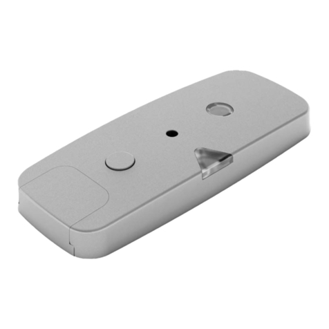
Install the Intelligent Heat Sensor underneath the range hood or on the wall.
Range hood installation
• See tables above for your required installation zone. Zone 1 (see image
1): above the central point of the burners (max. 6'' (15 cm) tolerance to
the side). Zone 2: see image 1.
• At minimum 4'' (10 cm) distance from range hood lights – 2'' (5 cm) for
LED lights.
• On a horizontal surface so that it is pointing directly downwards.
is clean (from dirt and grease) by using a detergent. Dry well prior to attaching
the Sensor.
1.
the protective backing from the Sensor mounting plate and stick the Sensor to
the underside of the range hood. Ensure that the LED on the side of the Sensor
points towards you (see image 2, A). Remove the Sensor from the plate (Sensor
2. Remove the red battery disconnection piece from the Sensor (see image
2, B), save for possible later use. Put the Sensor back on the mounting plate,
ensure that it goes the right way round, and ts tightly on the plate so that
there are no gaps.
3. Measure the distance between the range top and the range hood. For
standard distances between 18'' and 24'' (45 cm - 60 cm), no sensitivity level
adjustment is necessary. For all other distances set the Heat Sensor sensitivity
manually, see instructions on the reverse of this sheet.
Image 1
Image 2
Battery
disconnection
piece
Zone 1: above the central point of the cooker (max. 6” tolerance to the side).
6” (15cm)
B
A
Hob width 24'' (60 cm) - Heat Sensor installation options
Options
(height measured from range top)
Location
Range hood
(horizontal hoods only)
18'' – 32'' (45 – 80 cm)
Zone 1 (see image 1).
Range hood
(horizontal hoods only)
32'' – 40'' (80 - 100 cm)
Zones 1 and 2
(see image 1).
Wall
26 - 32'' (65 - 80 cm)
Mounting bracket required
(purchased separately).
Hob width 36'' (90 cm) - Heat Sensor installation options
Options
(height measured from range top)
Location
Range hood
(horizontal hoods only)
32'' – 40'' (80 - 100 cm)
Zone 1 (see image 1).
Wall
28 - 32'' (70 - 80 cm)
Mounting bracket required
(purchased separately).
STEP 2 - Install the Control Unit
Disconnect power. Connect the Control Unit between the range and the
power outlet
STEP 3 - Test the Stove Guard
1. Reconnect power. Wait for that control unit emits a ringing sound or approx.
30 seconds, then press the Sensor cover until the Sensor emits a beep.
2. Check that the Control Unit emits ringing sound. After a moment, the Heat
Sensor emits an alarm signal. Check that the cooker has no power, then return
power by pressing the Sensor cover once.
3. Check that the range turns on.
If the Heat Sensor does not respond, see troubleshooting, below.
The installation is now ready.
Instructions for wall installations are found in the mounting
bracket manual.
The Sensor can be attached also to the grease lter grid. Ensure that the surface
Allow the Intelligent Heat Sensor to rst adjust to room temperature. Remove
will emit a beep). Press the mounting plate rmly towards the surface to ensure
a secure t.
