Innokin iTaste DRV Instruction manual

WARNING:
1. The iTaste DRV is only intended for use by people
of legal smoking age (18+). The iTaste DRV is NOT
to be used by non-smokers, children, pregnant or
depression or asthma. The iTaste DRV is neither
intended for use, nor marketed as, a smoking
2. This unit may include small parts; Keep out of
reach of children and pets.
P
iTaste DRV as you damage may be caused to the
outer shell or inner components. The DRV is
-
dled.
D
damage or personal injury may occur.
I T
DRV
P
I
iTaste DRV.
Y T DRV P
P
sources of heat may damage your iTaste DRV. Do
DRV
8. Innokin is not responsible for DRV or Tank
T T
DRV uses 12/24DCV only
P DRV
The DRV and DRV Cord should not block or
• The Pedals or any of the controls in your car.
Y
T A I
P I
I
WARNING:
A
D DRV
• You should be able to reach the DRV easily
A
U
endanger those around you.
T S
Power supply: Car charger light socket 12/24DCV
Standby current: 5mA max
Fuse: 5A/250VAC
Maximum output voltage: 6.4V (unloaded)
Maximum output current: 5.0A
M W W
Resistance of clearomizer: 1.0 Ohm (minimum)
L 9.6V
O V W 2600m Ah
S C P 0.6 +/-0.2 ohm
P
carefully before using your iTaste DRV. Warranty
Quick User Guide
1. Connect the output cable to the DRV body. Insert the
DRV into a DC12V or DC24V car charger socket. The
LED
P ONOFF T
A
4.2V, 4.4V, 4.6V, 4.8V, 5.0V, 5.2V, 5.4V, 5.6V, 5.8V,
6.0V, 6.2V, 6.4V
4.
A T
LED
T OFF P ONOFF T
T DRV
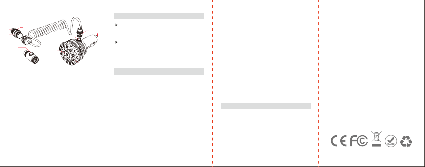
S C P I
1:A
2:Output port
3:Working indicator light
4:Output board
5:Output port
6:Output cable
7:Input port
8:Main body output
9:R
10:ONOFF
11:P LED
12:R
13:Main body
14:I
15:I
16:M
T
4.2V, 4.4V, 4.6V, 4.8V, 5.0V, 5.2V, 5.4V, 5.6V, 5.8V,
6.0V, 6.2V, 6.4V
S
FEATURES:
OPERATION GUIDE:
Scale Display Voltage:
Variable Voltage:
P
T
DRV
O T LED
T LED
T
W
W T DRV
M
2.
I
is correctly set in place.
I
DRV
LED
I
DRV
P
I
I
ONOFF
C DRV
F L
ONOFF LED
I
A I V
TROUBLESHOOTING:
12
3
4
5
16
6
715
14
13
8
9
10
11
12
Other Innokin Vaporizer manuals

Innokin
Innokin COOLFIRE IV User manual

Innokin
Innokin Z Biip User manual

Innokin
Innokin MVP User manual

Innokin
Innokin PRISM T18 CLEAROMIZER User manual

Innokin
Innokin iTaste SVD 2.0 User manual

Innokin
Innokin iTaste SVD 2.0 User manual

Innokin
Innokin itaste mvp 2.0 User manual

Innokin
Innokin Z BiiP User manual


