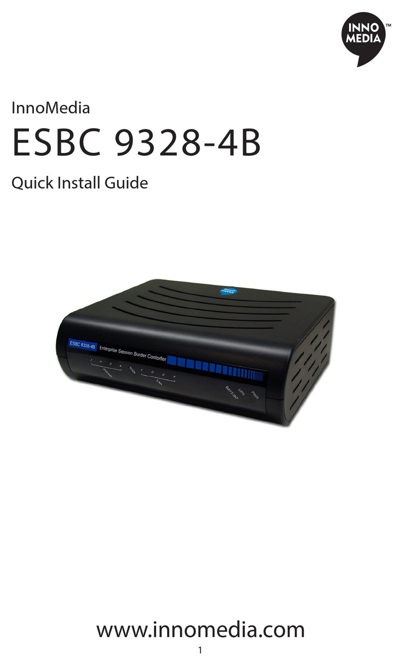
InnoMedia MTA 8328-1W User manual

www.innomedia.com April 2017
InnoMedia
MTA 8328-1W
Quick Install Guide
The InnoMedia MTA8328-1N is an integrated device providing telephony
service over a broadband network. This guide will help you to quickly install
and configure your unit so that you can start placing calls right away.
Package Contents
MTA8328-1N
12V Power Supply
Ethernet Cable and Phone Cable
Getting to Know Your MTA
MTA Out of the Box Setup
Before starting the Installation, make sure your broadband Internet access
device is powered on and your connection is up.
Plug the supplied power adapter into the MTA8328. The power LED will
show steady green.
Connect your phone into the PHONE port on the MTA using the
supplied Phone Cable.
Setup the MTA to connect to your Home Router.
For Ethernet Connection. If your MTA is located close to your
Home Router, connect the yellow Ethernet cable (supplied) into
the WAN port on the MTA and connect the other end into an
available Ethernet port on your router or LAN network. Then
proceed to step directly.
For WiFi Connection. Alternatively, connect the MTA to the Home
Router through a WiFi connection. Press the round button on the
top of the unit for about 5 seconds, the MTA will switch to “Setup
Mode” and the WiFi LED will change to solid yellow. Connect your
smart phone or PC to the MTA’s pdreset SSID shown on the back
of the unit, i.e., MTA8328-xxxxxx, product name followed by the
last 6 digits of MAC address. The MTA welcome portal web page
will show up on your smart phone/PC. If this page does not popup,
open the web browser and type in the following address:
http://192.168.199.1/wifisetup/
During setup, follow the instructions on the welcome portal. You
will need to select the WiFi SSID of your WiFi Access Point and
input the WiFi passphrase. For detailed instructions, please see
Error! Reference source not found..
Confirm that the MTA is successfully connected to the Home
Router and acquires an IP address as follows:
For Ethernet Connection. The WAN LED shows green for 100BT
connection, or shows amber for 10BT.
For WiFi Connection. The WiFi LED shows green. If it is not green,
repeat step .
Once the MTA connects to the voice service provider network, and
completes the registration and service provision process, you should
see a solid green PHONE LED light displayed.
Wireless Connection Optimizer (WCO)
The WCO test is designed to determine an ideal location for the MTA by
performing voice quality validation thru a WiFi connection.
1
One of the
following results will be displayed/announced after the WCO test is
completed:
Your device location is Excellent|Good|Not Good
If the test result is “Not Good”, one or more of the following steps are
recommended before running the WCO test again until the result is “Good”
or “Excellent”:
Change the location of the MTA. Decrease the distance between the
MTA and the WiFi router and/or avoid any large obstructions between
the MTA and WiFi router.
Switch to another WiFi channel.
Change WiFi frequency between 2.4GHz and 5 GHz to improve
reception.
1
Note that some WiFi routers may drop WCO packets for strict security
configurations.

www.innomedia.com April 2017
Note:
The WCO test can only be invoked when the WAN Ethernet is not
connected.
Run the WCO test only when the WiFi LED displays solid green as its
initial state.
The WCO test will run for 30 seconds. During a test period, the WiFi
LED changes its state to “blinking yellow” (0.5 sec ON | 0.5 sec OFF).
Execute the WCO test using any of the following two approaches:
Method 1: Dial ***8 from the phone connected to the MTA.
Off hook the phone, dial ***8, and the MTA interactive voice response (IVR)
will play “Wireless connection optimizer test is in progress, please wait…”
After the test is complete, the IVR will then announce the test result, as
well as displaying it through its respective LED state, as shown in Error!
Reference source not found.
Method 2: Double click the round button on the top of the MTA box.
Double click the round button on the top of the unit. After the WCO test
is complete, the result is displayed through its respective LED state.
Method 3: Device WEB console. Login to the MTA administrative web
console. Navigate to Telephony > Wireless Connection Optimizer page, and
click the <Start Test> Button. The test result will be displayed on the WEB
GUI page as well as through its respective LED state.
Making Calls
You are now ready to place calls. * Note that the MTA8328-1N
supports FAX transmission.
Accessing the MTA WEB Management Console
Once the MTA is connected to your Home Router, you may proceed to
access the MTA via the Web Browser from a PC connected to the same
router as the MTA.
Press ***1 on the phone which is connected to the MTA and get the
IP address of the MTA.
Type in the following address: http://<MTA-IP-Address>
The default username is: user, and default Password is: welcome
LED Representation
WCO Test State
WiFi LED Representation
WCO Initial State
Solid Green
WCO Result State (last for 20 secs)
Excellent
Solid Green
Good
Alternates between solid yellow and
solid green.
Not Good
Solid yellow
LEDs
Blinking State
MTA8328 LED States
PWR
Steady Green
Powered ON.
Off
Powered OFF.
WAN
Solid or Blinking
Green
WAN Ethernet 100BT link is active,
blinks with activity.
Solid or Blinking
Yellow
WAN Ethernet 10BT link is active,
blinks with activity.
Off
WAN Ethernet link is not connected.
Fast Blinking
Green
(0.25 secs on,
0.25 secs off)
WAN Ethernet 100BT link is active but
is unable to reach the Internet.
Fast Blinking
Yellow
(0.25 secs on,
0.25 secs off)
WAN Ethernet 10BT link is active but
is unable to reach the Internet.
Medium-Slow
Blinking Green (1
sec on, 1 sec off)
Device firmware is being upgraded.
The PHONE LED blinks in unison with
the WAN LED.
LAN
Solid Green
LAN Ethernet 100BT link is active.
Solid Yellow
LAN Ethernet 10BT link is active.
Off
LAN Ethernet link is not connected
LEDs
Blinking State
MTA8328 LED States
WiFi
Solid or Blinking
Green
WiFi is connected successfully and link
is active. Blinks with activity.
Medium-Slow
Blinking Yellow (1
sec on, 1 sec off)
WiFi is in the process of being setup
via the welcome portal.
Fast Blinking
Green
(0.25 secs on,
0.25sec off)
WiFi link is active but device is unable
to get an IP address, OR is unable to
reach a public IP address. This is the
same condition in which the "no
Internet connection" IVR is played.
Solid Yellow
WiFi is attempting to connect to the
AP.
Off
WiFi is disabled.
PHONE
Off
- No power, OR
- Device is initializing, OR
- Failed to register for voice services,
OR
- This line is disabled.
Steady Green
The device is ready to make calls.
Slow Blinking
Green (3 secs on,
1 sec off)
There are new voicemail messages.
Medium-Fast
Blinking Green
(0.5 secs on, 0.5
secs off)
The device is registered and ready to
make calls, and the line is in use.
Fast Blinking
Yellow (0.25 secs
on, 0.25 secs off)
One or more line diagnostics tests (GR-
909) failed. This state is cleared when
the GR-909 tests are run again and all
tests pass, or when the device is
rebooted.
Medium-Slow
Blinking Green (1
sec on, 1 sec off)
Device firmware is being upgraded.
The PHONE LED blinks in unison with
the WAN or WiFi LED.

www.innomedia.com April 2017
Troubleshooting
Problem 1: When the network is not connected, the MTA IVR (Interactive
Voice Response) system announces messages such as: “Your Internet cable
is not connected,” or “Check to see if your Internet service is down.”
Recommendations: Ensure that all cables (power, Ethernet) are properly
connected to the MTA. Make sure your broadband access device is
properly set up.
Problem 2. When the Network is connected, but there is no phone service
available, the MTA IVR announces the message: “Your device is not
registered with your service provider.”
Recommendations: Report the failure to your voice service provider for
their attention.
Federal Communication Commission
Interference Statement
The MTA8328 series products have been tested and found to comply with
the limits for a Class B digital device, pursuant to Part 15 of the FCC Rules.
These limits are designed to provide reasonable protection against harmful
interference in a residential installation. This equipment generates, uses
and can radiate radio frequency energy and, if not installed and used in
accordance with the instructions, may cause harmful interference to radio
communications. However, there is no guarantee that interference will not
occur in a particular installation. If this equipment does cause harmful
interference to radio or television reception, which can be determined by
turning the equipment off and on, the user is encouraged to try to correct
the interference by one of the following measures:
Reorient or relocate the receiving antenna.
Increase the separation between the equipment and receiver.
Connect the equipment into an outlet on a circuit different from that
to which the receiver is connected.
Consult the dealer or an experienced radio/TV technician for help.
This device complies with Part 15 of the FCC
Rules. Operation is subject to the following
two conditions: (1) This device may not cause
harmful interference, and (2) this device must
accept any interference received, including
interference that may cause undesired
operation.
IMPORTANT NOTE:
FCC Radiation Exposure Statement:
This equipment complies with FCC radiation exposure limits set forth for an
uncontrolled environment. This equipment should be installed and
operated with minimum distance 20cm between the radiator & your body.
Copyright Notice:
© 2017, InnoMedia Inc., All rights reserved. This documentation is the
proprietary intellectual property of InnoMedia Inc.
Other InnoMedia Gateway manuals

