InnotechRV JET-M-400C User manual

InnoTechRV
(For Rvs )and Trucks
InnoTechRV.com (A Division of WiPath Communications, LLC)
Add: 4845 Dumbbarton Ct., Cumming, GA 30040
Tel: 770 844 6218
Fax: 770 844 6574
E-mail:
Web:
info@innotechrv.com
www.InnoTechRV.com
www.InnoTechRV.com

SENSOR
2
TYRE GUARD
1
TYRE GUARD
JET-M-400C
(MONITOR)
JET-M1-400C
(MONITOR)
JET-M2-400C
(MONITOR)
1 Introduction
2 Function
Units Conversion Formulae
Temperature
F=9C/5+32
Note: C = Celsius; F = Fahrenheit
Pressure
1 Bar=14.5 psi
1 Bar=100 kPa
2
1 Bar=1.02 kgf/cm
“ ” button
“” button
SET button
Congratulations on purchasing the new InnoTechRV TPMS-X
Tire Pressure Monitoring System.This system is a safety system
for monitoring the vehicle’s tire pressure and temperature. It
consists of externally mounted wireless sensors, fitted to the
vehicles wheel tire valves, and a hand-held monitor. The sensor
will monitor the tire’s air pressure and temperature. The sensor
transmits the tire pressure and temperature information to the
dash-mounted/hand held monitor.
The monitor can be placed on the dashboard, on the sun visor or
mounted in any convenient place in the vehicle using the window
mount included.
PSI
KPa
Bar
2
Kgf/cm
Pressure
sensor
monitor
TempLeaking TEMPERATURE CONDITION icon
BATTERY CONDITION icon
Bar icon
KPa icon
PSI icon
Kgf/cm2 icon
˚C icon
˚F icon
NUMERICAL
INDICATING
SECTION
MONITOR icon
SENSOR icon
PRESSURE CONDITION icon
LEAKAGE icon
C
F
InnoTechRV InnoTechRV
The monitor’s function is to receive the temperature and pressure information
transmitted from the sensors fitted to each tire and display this information on the
screen in the specific units of measurement of your choice.
The monitor will emit an alarm when a tire pressure or temperature varies
markedly from the targeted tire pressure and/or temperature (refer section 4.)
The system will detect high or low air pressure as well as high temperature or
rapid leakage from the tires. The monitor will flash a red warning LED lamp and an
alarm will sound to remind the operator to check if the tires are high or low in air
pressure, there is leakage, a high temperature condition, the monitor ’s battery is
low, or there is a problem with a sensor. This advanced tire monitoring system
offers these great features and benefits, is reliable, lightweight and compact.
3 Installation & Operating Instructions
The following graphics identify the icons on the monitor.
Important; before installing the tire sensors:
a. ensure you have inflated the vehicle’s tires to your required pressures. Note: It
is recommended to set tire pressures at those recommended by the
manufacturer or listed in the vehicle’s handbook,
b. ensure the monitor battery is fully charged and is in the tire alignment mode,
c. ensure batteries have been fitted to each sensor.

Hold down the middle button of the monitor for 5 seconds to enter into Standard
Settings Mode (left graphic below). The first tire position will be selected. Press
the “ ” or “ ” button to set the required pressure for this tire position then press
the middle button to select the next tire and repeat this sequence to set the
standard pressure on each of the remaining tires.
4
TYRE GUARD
3
TYRE GUARD
Installation of the Sensor and anti-theft device
A
Valve Anti-theft
Devce
Driver
c
The sensors of the INNOTECHRV TPMS-X have
an optional anti theft ring to prevent the sensors
being stolen. If you wish to fit these then, with
the sensor off the valve stem, place the anti-
theft ring over the valve stem, with keyed face
facing out, replace the sensor and then with the
anti-theft ring knobs fitted to the slots of the
sensor tighten the grub screws with the hex key
provided.
Programming Standard Settings
Bar
Pressure Temp
Bar
Pressure
C
Installation of the Monitor
InnoTechRV InnoTechRV
Tire alignment mode
Hold down the buttons simultaneously on the monitor for 5 seconds to enter
tire alignment mode, and press either “ ” or “ ” button to select the specific tire that
needs to be aligned.
Screw a sensor to the Tire valve stem and the current pressure will be displayed against the
corresponding flashing Tire icon on the screen. Once the Tire is aligned successfully the
green light appears on the monitor. The red LED light appears on the monitor if the sensor
hasn’t been aligned and “- - -” also appears on the monitor.
When all tire sensors have been aligned with the monitor, exit tire alignment mode by again
holding down the “ ” and “ ”, buttons simultaneously on the monitor until the monitor
beeps (approx 5 seconds).
To check the pressures and temperatures, scroll through the selected tire positions using the
left or roght buttons. The monitor will indicate the pressure and then the temperature of each
tire. After your checks are completed, the backlight will go out and the monitor will indicate
the Tire pressure of the selected Tire.
“ ” and “ ”
Note: If the sensor is to be removed from one valve and fitted to another valve, you must
delete the current setting on the monitor and realign this sensor to the new tire. To delete an
aligned sensor from a tire, whilst in tire alignment mode, select the tire position and then hold
down the middle button until “- - -“ appears on the monitor.
Note: The monitor may initially show abnormalities until you have set your required pressures
and units of measurement. These will be done in the Standard Pressure Setting and unit
selection setting below.
Note:
1. Always install the sensor when the Tire is cold
2. Please check each Tire valve is not damaged.
3. Check to ensure there are no leaks and the
sensors are firmly secured to each Tire valve.
The monitor may be mounted using the pedestal supplied. The monitor can be
fixed to a suitable surface in the vehicle, sun visor, dashboard etc. It has a built-in
lithium battery or you may wish to use the charger provided to power the monitor
continuously.
Once you have completed setting all the tire pressures, then set your preferred
units of temperature and pressure measurement, “kpa”, “Bar”, “PSI” and “kgf/cm2”
for pressure units and “F” and “C” for temperature, by pressing the “ ” or “ ”
buttons. Hold down the middle button for 5 seconds to exit the Standard Settings
mode.
TYRE GUARD
5
TYRE GUARD
6
Sensor battery replacement
Note:
Power up
BATTERY
B
SENSOR SENSOR COPING
“+” POLE OF BATTERY
C
Reading Current Tire Conditions
A
Bar C
Pressure Temp
D
Battery Low Indicators of the Monitor and Sensor
monitor
sensor
A
Charging the Monitor
Note: Please keep the monitor in a cool environment when charging.
A B C
monitor monitor monitor
InnoTechRV InnoTechRV
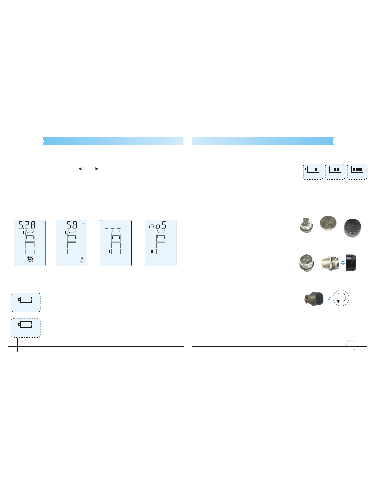
Whilst in Standby mode, press “ or “ button to check the air pressure and
temperature of each of the tires in turn starting with the front left tire (graphics A &
B right).
The monitor indicates “- - -” if a specific sensor ’s alignment is lost from the
monitor. Refer to Tire Alignment Mode to realign sensor (graphic C right).
The monitor will indicate the “no S” signal whenever a sensor is either out of
range or may be faulty. (graphic D right).
” ”
C
B
When the monitor battery charge is low, the battery icon and
“MONITOR” icon on the screen flash, the beeper gives a 10
second intermittent alarm. The monitor will then beep every 30
seconds when it is within 5 minutes of total discharge.
When a tire sensor has a low battery, the battery icon and
“SENSOR” icon together with the corresponding tire icon flash
on the screen and a 10 second intermittent alarm will sound. If
the power of any of the sensors becomes too low, please
replace the corresponding battery immediately.
The built-in lithium battery of the monitor is re-
chargeable. Please connect the 12/24V DC
charger into the port at base of the monitor, and
then insert the adapter plug into the port of the
vehicle's 12/24V DC accessory port. It takes
approximately 6 hours to fully charge the monitor.
The battery icon cycles as it is charging (as above) and the monitor will give beep
and the charging icon will disappear once charging is complete. Note: Please
keep the monitor in a cool environment when charging.
Replace the corresponding sensor ’s battery
when the monitor indicates a low battery.
Unscrew the plastic cap from the sensor,
take out the battery and replace with a new
button cell battery, (CR 1632). Ensure the
“+” terminal is touching the upper bracket.
Screw down the cover.
Quickly press SET button to enter into stand-by mode from the powered off
state.
Note: Once the monitor is on, the information from all Tires can take up to 4
minutes to be received in normal conditions. When the sensors are in an area of
strong interference or in very cold conditions, the monitor may not receive the
signal. Pull out the monitor ’s antenna to increase the strength of the signal.
The battery model required for the
sensors is a CR1632 button battery.
The "+" and "-" pole of sensor battery
must be placed in the correct position
with the “+” terminal facing up; failure to
do so may cause the sensor to burn out.
In order to make sure that the battery is
replaced correctly, enter Tire alignment
mode and delete the alignment of the
respective sensor and realign it again.
1.
2.
3.

7
TYRE GUARD
8
TYRE GUARD
Power off
Standby Time
4 Warning Conditions
Rapid Leakage
Pressure
Leaking
Bar
Temp
C
Slow Leakage
High Temperature Warning: Stage 1
High Temperature Warning: Stage 2
Bar
Pressure
Leaking
Temp
C
Low Pressure Warning: Level 1
Low Pressure Warning: Level 2 Bar
Pressure
Bar
Pressure
InnoTechRV InnoTechRV
Hold down the middle button for at least 8 seconds, and the monitor will
automatically switch off. Please note: the system will first enter into the setting
mode 5 seconds after holding down SET button, continue holding down the SET
button for a further 3 seconds or more to power off the monitor.
Note: Whether the monitor is turned on or off, the sensors are always in standby
mode.
The monitor has an intelligent 15 minute suspend mode. The monitor goes into
suspend mode to save power after the vehicle has been switched off for more
than 15 minutes. When the vehicle is started, the monitor automatically turns on
and connects to the vehicle’s sensors.
The INNOTECHRV TPMS-X has two primary functions, monitoring the
temperature and pressure conditions of the vehicle’s tires. The following are the
abnormal conditions that will trigger a warning.
When the air pressure of a tire drops more than 0.2 Bar (3psi)
within 2 minutes, the monitor will signal an audible alarm and
the corresponding icon will flash on the monitor’s screen to
indicate which tire has the abnormal air pressure and what its
current air pressure reading is. The air pressure icon will also
flash along with the flashing red LED on the monitor.
When the air pressure of a tire drops more than 0.2 Bar (3psi)
over a period of between 2~10 minutes, the monitor will signal
an audible alarm and the corresponding icon will flash on the
monitor ’s screen to indicate which tire has the abnormal air
pressure what its current air pressure reading is. The air
pressure icon will also flash along with the flashing red LED
on the monitor, as the right graphic shows.
Note: If there is a fast or slow leak the sensor will send a
message to the monitor whether driving or stationary.
When the temperature inside the tire exceeds 167oF
(75oC) the system will give a stage 1 high temperature
alarm and the monitor will indicate the position of the tire
with the abnormal temperature along with its current
temperature. Abnormal temperature is indicated by the
flashing red LED on the monitor and the temperature icon
flashing on the screen.
When the temperature inside the tire exceeds 185 oF (85
oC) the system will give a stage 2 high temperature alarm
and the monitor will indicate the position of the tire with
the ab normal te mpera ture a long w ith its cu rrent
temperature. Abnormal temperature is indicated by the
flashing red LED on the monitor and the temperature icon
flashing on the screen.
When the actual tire pressure is equal to or falls below
85% of the set pressure the system will give an alarm and
the monitor will indicate the position of the tire with the
abnormal air pressure and its current pressure. The low
pressure is indicated by the flashing red LED on the
monitor and the pressure icon flashing on the screen.
When the actual pressure is equal to or falls below 75%
of the set pressure the system will give an alarm and the
monitor will indicate the position of the tire with the
abnormal air pressure and its current air pressure. The
low pressure is indicated by the flashing red LED on the
monitor and the pressure icon flashing on the screen.

TYRE GUARD
910
TYRE GUARD
Low Pressure Warning: Level 3
High Air Pressure Warning
Multi-Warning Indication
Pressure
Leaking
Bar
Slow
Slow
Fast
Bar
Pressure
Bar
Pressure
Sensor Abnormality Indication
Notes:
InnoTechRV InnoTechRV
When the actual pressure is equal to or falls below 50%
of the set pressure the system will give an alarm and the
monitor will indicate the position of the tire with the
abnormal air pressure and its current air pressure. The
low pressure is indicated by the flashing red LED on the
monitor and the pressure icon flashing on the screen, as
the graphic on the right shows.
When the actual pressure is equal to or greater than
120% of the set pressure the system will give an alarm
and the monitor will indicate the position of the tire with
the abnormal air pressure and its current air pressure.
The low pressure is indicated by the flashing red LED on
the monitor and the pressure icon flashing on the screen,
as the graphic on the right shows.
When there are many kinds of abnormities with one
Tire simultaneously, the monitor will indicate all the
various abnormalities, as the graphic on the right
shows.
1.
2. When there are abnormities with two or more tires at
the same time, the respective tire icons with the
abnormalities will all flash on the screen. In this
situation the current tire reading being displayed will
be indicated by that tire icon flashing more rapidly
than the other icons.
If the monitor does not receive a signal from one or more of
the sensors within 20 minutes of coming out of standby mode,
the audible alarm will sound for 15 seconds along with the
flashing red LED on the monitor. The corresponding icon of
the abnormal sensor will also flash and indicate “no S” which
indicates there is either a fault with the sensor, the sensor is
damaged or the sensor is out of range. The system will alarm
every 20 minutes if the monitor still can't receive the signal
from the sensor, as the graphic on the right shows.
Note: When the monitor has been off or in standby mode, the monitor will display
“no S” instead of the detailed pressure and temperature readings. The monitor
will indicate the correct readings within 4 minutes of activation.
In an alarm condition the monitor will sound a continuous audible alarm for 15
seconds with the flashing red LED and the back light will remain on for 5 minutes
along with the corresponding faulty tire icon flashing. Pressing the “ ” or “ ”
button will stop the audible alarm. Shortly afterwards the back light will
automatically go off but the red LED will remain on until the fault condition clears.
The system alarm will sound again after one hour to further remind the operator if
the condition has not cleared.
When a sensor is removed to inflate or deflate a Tire, this will cause the sensor to
detect rapid and/or slow leakage because the sensor has suddenly detected
zero pressure. Once the sensor is refitted the monitor will return to normal and
the alarm will clear within approximately 10 minutes.
If you wish to add further sensors to the monitoring system, i.e. fitting sensors to
an additional trailer, etc. refer to procedure 3, Installation & Operating
Instructions.

11
TYRE GUARD
12
TYRE GUARD
5 Technical Specifications
Sensor
Working Temperature 14 F TO 185 F (-10°C -- 85°C)
Working Humidity 0 -- 95%
Dimension 24 x 21 x 21mm
Weight 11g(±1g)
Battery Voltage 3V DC (CR1632)
Battery Life 1 year
Standby Current 500nA
Working Current 6mA
Pressure Measure Range 0 psi -- 232 psi(0 bar– 16 bar)
Pressure Measure Precision ± psi(±4.35 0.3 bar)
Temperature Measure Range 14 F TO 185 F (-10°C -- 85°C)
Temperature Measure Precision ±3°C
Signal Transmitting Frequency 433.92 MHz
Operating Distance up to 20M(65ft)Booster recommended
Monitor
Working Voltage 3V DC
Working Temperature -4 F TO 140 F ( )-20°C -- 60°C
Working Humidity 0 -- 90%
Standby Current 0.1mA
Working Current 15 mA
Dimension
Monitor size:82mm×55mm×23mm (JET-M-400C)
Monitor size:87mm×55mm×20mm (JET-M1-400C)
Monitor size:82mm×52.5mm×16.5mm (JET-M2-400C)
Signal Receiving Frequency 433.92 MHz
Color of Backlight White
6 Box Contents
Description Quantity
Tire Sensors (TPMS-X)
Monitor One (1)
Bracket One (1)
12/24 V DC Accessory Power Socket Adapter One (1)
Sensor anti-theft security devices X = no sensors (4-22)
Hex Allen Key One (1)
User Manual One (1)
。 。
。 。
。 。
X = no. of sensors (4-22)
If towing or over 25ft(Receiver to rear Tire)
InnoTechRV InnoTechRV
This system is distributed by:
InnoTechRV (A division of WiPath Communications, LLC.)
4845 Dumbbarton Ct.
Cumming, GA 30040
P: 770 530 0274
E: info@innotechrv.com
W: www.innotechrv.com

13
TYRE GUARD
14
TYRE GUARD
For customer reservation
Name:
Model No.:
Date of Purchase:
Place of Purchase:
Note:
1. We offer one-year warranty and free repair services for the
products from the date of purchase.
2. We offer lifetime maintenance services for our products.
3 . O u r wa r r a n t y ex cl u d e s t h e no r m a l ab r a s i o n of an y
subassemblies and accessories, any damages from improper use,
ac c i de n t s a n d dis m ant l e men t , a n d the d ama g es o f any
accessories.
4. Please keep this part and the commercial invoice as the
guarantee for the repair and examination of the products during
warranty.
Distributor:
(Signature and seal)
(This guarantee card will become effective upon the seal of
the distributor.)
Thank you for choosing our products.
Please carefully fill in the following form.
Name:
Post Code:
Address:
Model No.:
Tel:
Invoice No.:
Date of Purchase:
Name of the Distributor:
What makes you choose our products?
□Economy □Service □Advert □Other
□Quality □Website □Recommendation from friends
Please fill in this card and send it back to our after service
department. It will be the main guarantee for your right to
gain the after services during the warranty.
InnoTechRV InnoTechRV
This manual suits for next models
3
Table of contents
Popular Automobile Accessories manuals by other brands

travall
travall TDG 1635 Fitting instructions

Metra Electronics
Metra Electronics 99-7506 installation instructions

Cardigo
Cardigo ANTI-MARTEN DUAL instruction manual

Yakima
Yakima 8002623 quick start guide

ALEX ORIGINAL
ALEX ORIGINAL 7486-1203 instruction manual

Badabulle
Badabulle B070000 instruction manual


Fiamma
Fiamma Carry-Bike SE Installation and use instructions

STO N SHO
STO N SHO SNS 337 Installation procedures

Thule
Thule AeroBlade Edge Raised Rail instructions

DriveRight
DriveRight CarChip 8210 Online help

Hauler Racks
Hauler Racks ECONO TRUCK UETR Series instructions

Parkmate
Parkmate RVM-043A user manual