Innova DS200 User manual

USER S MANUAL
DS200
Channel Graphing Multimeter

2
Introduction
INTRODUCTION
The DS200 Channel Graphing Multimeter is an automotive industry compact 2 channel Bluetooth graphing multimeter connected to a smart
device application that allows for both the initial information to be read and received, but also is opening the gateway into the future of data
intelligence and interpretation. The meter connected to the smart device application, and it can be one of many that can be connected to the
application to provided data for interpretation and analysis to give the user intelligent data; and it is a 2-channel intelligent system; this is the first
set towards data intelligence.
The DS200 Channel Graphing Multimeter (hereafter “The Meter”) is a battery powered multimeter capable of handheld and remote.
The Meter meets CAT III IEC 61010-1 3rd edition and 61010-2-030 standards. Overvoltage category III (CAT III) defines a level of safety
appropriate for the transient over voltages present in fixed equipment installations at the distribution level. This includes the mainsinstallation of a
building, distribution boards, busbars, and permanently connected equipment. Do not use this multimeter for CAT IV circuits, which includes any
mains circuits not protected by a building’s breakers.
PACKAGE CONTENTS
Innova Meter (1)
1.5V AA Alkaline Batteries installed (2)
12A HRC fuse installed (1)
Test Leads (3)
Carrying case (1)

3
Safety Information
SAFETY INFORMATION
WARNING: Denotes a potentially hazardous situation that may result in injury or death
CAUTION: Denotes a potentially hazardous situation that may result in damage to the meter
NOTE: Denotes a situation that may result in degraded or incorrect measurement
§ Use caution in the operation of this device. Improper use may
result in injury or death. Read this user manual before operating
the meter.
§ Always remove leads before opening the case.
§ Do not operate the meter unless it is fully assembled with both
case screws tight.
§ Only use appropriately rated fuses.
§ Always check for damage before use. Pay special attention tothe
test leads for signs of damaged insulation or exposed
conductors. Immediately replace damaged leads.
§ Only use test leads that are rated to at least CAT III 600VKeep
fingers behind the guards on the leads.
§ Use caution working with voltages above 30VAC rms, 42VACpeak,
or 60VDC. Voltages this high pose risk of shock.
§ Never apply more than 600V between any terminal and earth
§ ground.
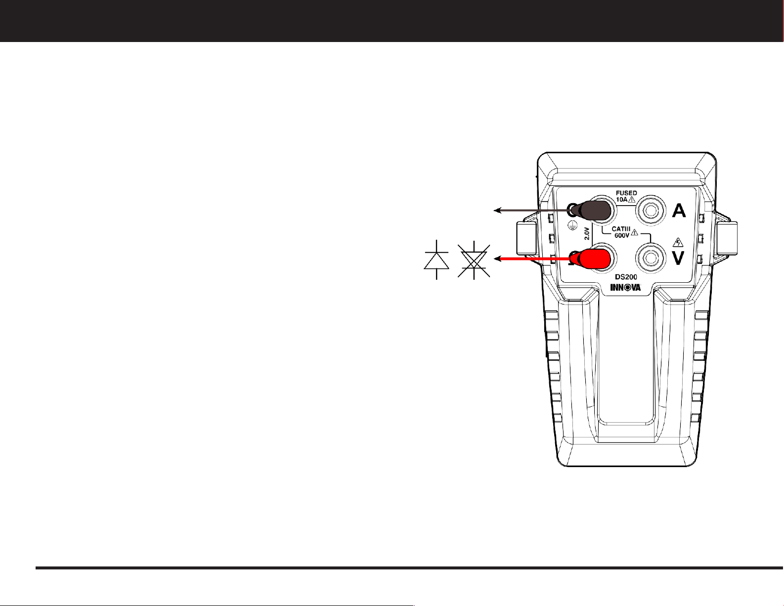
§ Do not apply more than 2.0V to the auxiliary terminal with respect
to Common. Doing so may draw unexpected currents and trigger
protection circuits. In this event, basic functionalitywill automatically
return within one minute. Accuracy may be adversely affected for
up to five minutes.
§ Error messages may appear on the user interface. Read these
messages for further information
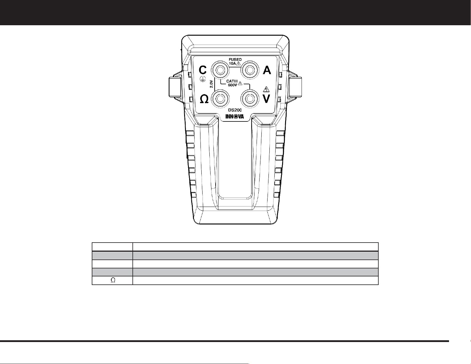
TABLE 1 SYMBOLS
Caution: Risk of Electric Shock. Refer to operating instructions.
Important Information: Refer to operating instructions.
CATIII
This instrument is rated for installation category III per IEC 61010.
Double Insulation
Terminal protected by fuse. Current limit of 10A RMS.
Conforms to European Union Directives
Do not exceed 600V with respect to ground.

4
Introduction
TABLE 2 TERMINALS
Terminal
Description
C
Common terminal for all measurements
A
Input terminal for measuring currents to 10A RMS (AC and DC)
V
Input terminal for measuring voltages to 600V RMS (AC and DC)
Input terminal for measuring resistance, diode drop and voltages up to 1.2V

5
Basic Measurement Instructions
Measuring Voltage
MEASURING VOLTAGE
WARNING: Risk of Electrocution. For determining whether a circuit is “live” exercise caution if the meter does not report a voltage. This
may indicate a poor connection to the circuit being tested. Make sure the probe tips are fully in contact with the circuit before assuming the
circuit is safe.
Two of the DS200 Multimeter’s input terminals are capable of making basic
voltage measurements:
The V terminal can measure up to 600V RMS and is intended for traditional
AC and DC voltage measurements.
The Ωterminal can measure up to 1V peak (~0.7V RMS for pure-sineAC) and
allows for several new measurement techniques described later in this
manual.
See the ratings section for further details on the measurement ranges.
Figure 1: Basic Voltage Measurement

6
Basic Measurement Instructions
Measuring Current with the Internal Current Shunt
MEASURING CURRENT WITH THE INTERNAL CURRENT SHUNT
WARNING: Exercise care when connecting in series with a circuit, especially those containing motor(s). Sudden disconnects may create
higher than expected voltages due to inductive kick.
WARNING: Perform a Fuse Check before measuring currents withthe internal
current shunt. Exercise caution in determining whether a circuit is “live” if the
meter does not report a current. This may indicate either a poor connection or
a blown fuse.
NOTE: AC current range is limited by the instantaneous current. Peaks above
the listed limits will result in incorrect readings. Derate AC current limits with
high crest factors accordingly.
§ Disconnect power from the circuit to be measured.
§ Break the circuit and wire the meter in series through the “A” and “C”
terminals.
§ Positive DC current flows into the “A” terminal.
Figure 2: Basic Current Measurement

7
Basic Measurement Instructions
Measuring Current with an External Current Shunt
MEASURING CURRENT WITH AN EXTERNAL CURRENT SHUNT
NOTE: This function may not be compatible with all scan tools. Please verify its compatibility before using it.
WARNING: This measurement mode is capable of measuring currents of many orders of magnitude larger than is typically possible with a
handheld meter. Exercise caution while interfacing high ampacity circuits.
NOTE: The accuracy of this measurement mode depends on the
accuracy of the external current shunt used. Account for this ac-
curacy dependency in your measurements.
The Ωterminal can measure small voltages, with a resolution of as
fine as 25nV per count and a noise floor as low as 1µV. This can be
used to with external current shunts to measure currents over a very
wide dynamic range. See the ratings section to guide shunt size
selection.
It is possible to use the existing wiring for the current shunt, and in
doing so take rough current measurements without breaking the
circuit.
With very low voltages it is recommended to minimize the loop area
of the measurement probes by either twisting them together or
using a BNC adaptor.
Figure 3: External Current Shunt

8
Basic Measurement Instructions
Measuring Resistance
MEASURING RESISTANCE
NOTE: Do not measure resistance on a live circuit. Doing so will result in incorrect readings and may engage the internal protection
circuitry. Should this occur, wait 5 minutes before taking further measurements.
§ Resistance is measured between the Ωand C terminals. Polarization is not important.
§
The meter uses a 100nA test current in its MΩranges and a 100uA test
current in its kΩranges.
Figure 4: Resistance Measurement

9
Basic Measurement Instructions
Diode Testing
DIODE TESTING
NOTE: Do not use the diode test functionality while connected to a live circuit. Doing so will result in incorrect readings and may engage
the internal protection circuitry. Should this occur, wait 5 minutes before taking further measurements.
§ To test diodes or other silicon junction devices, a test current is
pushedthrough the device under test and the resulting voltage is
measured.
§ Positive test current flows out of the Ωterminal and into the C terminal.
The test current is 100µA.
FWD REV
Figure 5: Diode Measurement

10
Basic Measurement Instructions
Using a BNC Adaptor
USING A BNC ADAPTOR
NOTE: This function may not be compatible with all scan tools. Please verify its compatibility before using it.
The 4 terminals are arranged with 0.75” spacing to allow for use of a standard BNC adapter. Measurements using the A or Ωterminals can be used
with the C terminal as usual.
§ To use a BNC adapter with the “V” input, use the “A” terminal as the common input. The “A” and “C” terminals are internally connected with a
low impedance (<=20mOhms).
Figure 6: BNC Adaptors for Ω,V, A Inputs

11
Two Channel Measurements
Measuring Small Resistances/Calibrating a Current Shunt
Your DS200 Multimeter is capable of reading any two of its three channels simultaneously.
NOTE: Measurements using the internal current shunt will experience a degree of
crosstalk due to the impedance of the Common lead. Other measurement types
will also experience this crosstalk, but it should be negligible.
MEASURING SMALL RESISTANCES / CALIBRATING A CURRENT
SHUNT
The DS200 Multimeter can be used to measure small resistances in a live circuit. The
meter simultaneously measures the current and the corresponding voltage with the
precision voltage channel (Ω), and then finds the slope to calculate resistance.
This can be done with either the internal current shunt or an external current clamp.
Using a current clamp allows the measurement to be done without breaking the circuit
and allows for test currents above 10Amps.
Wire the meter in as shown and enable the measurement mode. Apply a test current
and run the analysis.
The analysis works best with several points along the curve. Therefore, the optimal test
current has a large magnitude and a strong time varying component below 1kHz. Often
this test current can be the current already present within the system due to normal
operation. For example, an AC system’s steady state or a DC systems startup transient
may provide sufficient data.
Figure 7: Current Clamp and Current Shunt Comparison

12
Two Channel Measurements
Power Factor
POWER FACTOR
Power Factor compares apparent power and actual power and is a measure of how effectively a load uses available power. This measurement
requires voltage and current measurements.
Current measurement can be done with either internal or external current
shunt mode. Power Factor is a “unitless” measure, so the gain accuracy of
the measurements does not affect the measurement accuracy. Therefore, the
existing wiring can be used as an external current shunt without calibration.

13
Maintenance
Opening Up Your DS200 Multimeter
OPENING UP YOUR DS200 MULTIMETER
WARNING: To avoid electric shock, disconnect test leads from the meter before opening the meter.
1. Disconnect all test leads.
2. Unscrew both retaining screws from the bottom of the casewith a Phillips head screwdriver.
3. Separate the two halves.
4. Taking special care not to bend the circuit board, grasp the circuit board near the connectors and pull it out of the top half of the
enclosure.
5. Your meter is now fully disassembled. The batteries, fuse and reset button are now accessible.

14
Maintenance
Closing your Innova Multimeter
CLOSING YOUR INNOVA MULTIMETER
WARNING: Risk of electrical shock. Do not operate the meter while partially disassembled.
1. Place the PCB in the bottom enclosure half. Use the “J” shaped fin for alignment with the corresponding cut-out in the PCB.
2. Close the two halves together.
3. Replace both screws. Tighten firmly.

15
Maintenance
Battery Replacement
BATTERY REPLACEMENT
1. Open the DS200 Multimeter per directions above.
2. Remove old batteries.
3. Observe the battery polarity indication on the circuit board. Insert 2 new AA 1.5V batteries as shown on the circuit board.
4. If you have inserted the batteries with the correct polarity, the Innova Multimeter’s LED will blink slowly several times before turning off.
If the light does not blink, check the battery's polarity.
5. Close the Innova Multimeter per direction above.
CLEANING
§ Gently wipe the assembled meter with a damp cloth.
§ Do NOT touch or apply cleaning agents to the circuit board.
§ Do NOT use any solvents or other cleaning agents while cleaning your Innova Multimeter. The outer housing is a polycarbonate-based
material and may be damaged by incompatible cleaners.

16
Maintenance
Fuse Test
FUSE TEST
WARNING: Always perform a Fuse Test before using the internal current shunt measurement mode.
1. Perform a resistance measurement with the C and Ωterminals connected.
2. If the resistance measured is greater than 0.5Ω,replace the fuse*
* The resistance mode on the Innova Multimeter is not accurate below
1Ω.The actual resistance of
the fuse should be 20mΩ.
FUSE REPLACEMENT
WARNING: Only use appropriately rated replacement fuse.
1. Open the DS200 Multimeter per direction above.
2. Gently remove the existing fuse from the holder.
3. Replace fuse only with appropriately rated replacement.
4. Recommended model:
§ Reomax 632.300.12
§ Size 3AG 12A holds 600V 10kA minimum interruption.
5. Close the Innova Multimeter per direction above.

17
Replacing the SD Card
REPLACING THE SD CARD
NOTE: This function may not be compatible with all scan tools. Please verify its compatibility before using it.
WARNING: To avoid electric shock, disconnect all leads from the meter.
NOTE: Only use FAT32 formatted SD cards up to 32 gigabytes. Larger SD cards or cards formatted differently cannot be written to memory.
1. Open the meter per the directions above.
2. Press the SD card further into the slot until you feel a click.
§ Release: The SD card will eject.
3. Remove old SD card and insert new SD card.
4. Push the card in with your finger until you feel a click.
5. Close the meter per the directions above.

18
Resetting Your Innova Multimeter
RESETTING YOUR INNOVA MULTIMETER
WARNING: To avoid electric shock, disconnect all leads from the meter.
1. Open the meter per the directions above.
2. Press and hold the button shown for 5 seconds.
3. Close the meter per the directions above.

19
General Specifications
GENERAL SPECIFICATIONS
Accuracy is specified for 1 year after calibration within 18 to 28C. Accuracies listed are for single-channel measurements only. Multi-channel
measurements may degrade accuracy. For extended specifications visit www.Innova.com.
All AC ranges are RMS assuming a pure sinusoid (crest factor √). Derate ranges linearly with increasing crest factor.
Maximum Voltage between
anyterminal and earth ground
600V
Surge Protection
6kV peak per IEC 61010 -1 600V CATIII
Fuse for A input
12A Reomax 632.300.12
Operating Altitude
Up to 2000m
Maximum Temperature Range
5C to 40C
Nominal Temperature Range
18C to 28C. Derate accuracy outside of this range
Input Power
3V 100mA from installed batteries
Battery
2x AA Alkaline, NEDA15A IECLR6
Battery Life
1 year typical standby
50 hours typical continuous active use
Size
1.75” x 4.5” x 1.25”
Weight
4.3 oz
Safety Compliance
EN61010-1:2010 Measurement Category III 600V
EN61010-2-030
Pollution Degree
2
RF Communications
2.4 GHz ISM Band
Bluetooth Low Energy
RF Communication Range
Free Space: Up to 50m
Electromagnetic compatibility
FCC Part 15.247 Subpart C
ETSIEN 300-328 V1.7.1
EN 61326-1:2013 per EN 55011:2009 + A1: 2010 / ClassA Radiated Emissions
EN 61326-1:2013 / ETSI EN301-489-1 V1.9.2 / EN 301-489-17 V2.2.1/ Immunity Testing

20
General Specifications
Voltage, Terminal V:
Current, Terminal A:
DC Range
AC Range
Resolution
Noise Floor
Accuracy
(%+counts)
10 A
9 A
3.8 µA
120 µA
0.5 + 50
8.5 A
6 A
1.9 µA
60 µA
0.5 + 50
6 A
4.5 A
1.3 µA
40 µA
0.5 + 50
5 A
3.5 A
1 µA
30 µA
0.5 + 50
3.5 A
2.5 A
0.7 µA
20 µA
0.5 + 50
2.75 A
2 A
0.5 µA
15 µA
0.5 + 50
1.75 A
1.25 A
0.4 µA
10 µA
0.5 + 50
Resistance:
Range
Resolution
Noise Floor
Accuracy
(%+counts)
9 MΩ
1.5 Ω
50 Ω
1.0+ 50
8 MΩ
1 Ω
35 Ω
1.0 + 50
6 MΩ
750 mΩ
25 Ω
1.0 + 50
4 MΩ
500 mΩ
20 Ω
1.0 + 50
3 MΩ
375 mΩ
12 Ω
1.0 + 50
2 MΩ
250 mΩ
8 Ω
1.0 + 50
9.6 kΩ
1.5 mΩ
48 mΩ
1.0 + 50
8.2 kΩ
1 mΩ
32 mΩ
1.0 + 50
6.1 kΩ
750 µΩ
24 mΩ
1.0 + 50
4.1 kΩ
500 µΩ
16 mΩ
1.0 + 50
3 kΩ
375 µΩ
12 mΩ
1.0 + 50
2 kΩ
250 µΩ
8 mΩ
1.0 + 50
DC Range
AC Range
Resolution
Noise Floor
Accuracy
(%+count)
y
600 V
275 µV
9 mV
0.5 + 20
600 V
430 V
140 µV
5 mV
0.5 + 20
455 V
320 V
95 µV
3 mV
0.5 + 20
365 V
255 V
70 µV
3 mV
0.5 + 20
260 V
185 V
50 µV
2 mV
0.5 + 20
200 V
140 V
35 µV
1090 µV
0.5 + 20
135 V
95V
25 µV
730 µV
0.5 + 20
60 V
45 V
20 µV
610 µV
0.5 + 20
40 V
30 V
10 µV
305 µV
0.5 + 20
30 V
22 V
6.4 µV
205 µV
0.5 + 20
25 V
18 V
4.8 µV
155 µV
0.5 + 20
18 V
12 V
3.2 µV
105 µV
0.5 + 20
14 V
10 V
2.4 µV
80 µV
0.5 + 20
9 V
6 V
1.6 µV
55 µV
0.5 + 20
1000 mV
700 mV
300 nV
10 µV
0.5 + 20
670 mV
475 mV
150 nV
5 µV
0.5 + 20
500 mV
350 mV
100 nV
4 µV
0.5 + 20
400 mV
275 mV
75 nV
3 µV
0.5 + 20
280 mV
200 mV
50 nV
2 µV
0.5 + 20
220 mV
150 mV
40 nV
2 µV
0.5 + 20
150 mV
100 mV
25 nV
1 µV
0.5 + 20
Table of contents
Other Innova Multimeter manuals