Innovate Motorsports LC-1 User manual
DB Digital Air/Fuel Gauge
(with Innovate Motorsports text)
LC-1 Quick Start Guide
1. Wire the LC-1 per the unit’s instructions
2. Connect the gauge’s RED wire to a switched 12 volt source
(ignition switched).
3. Connect the gauge’s BLACK ground wire at the LC-1’s
White ground point. This ground point should ideally be an
engine block ground.
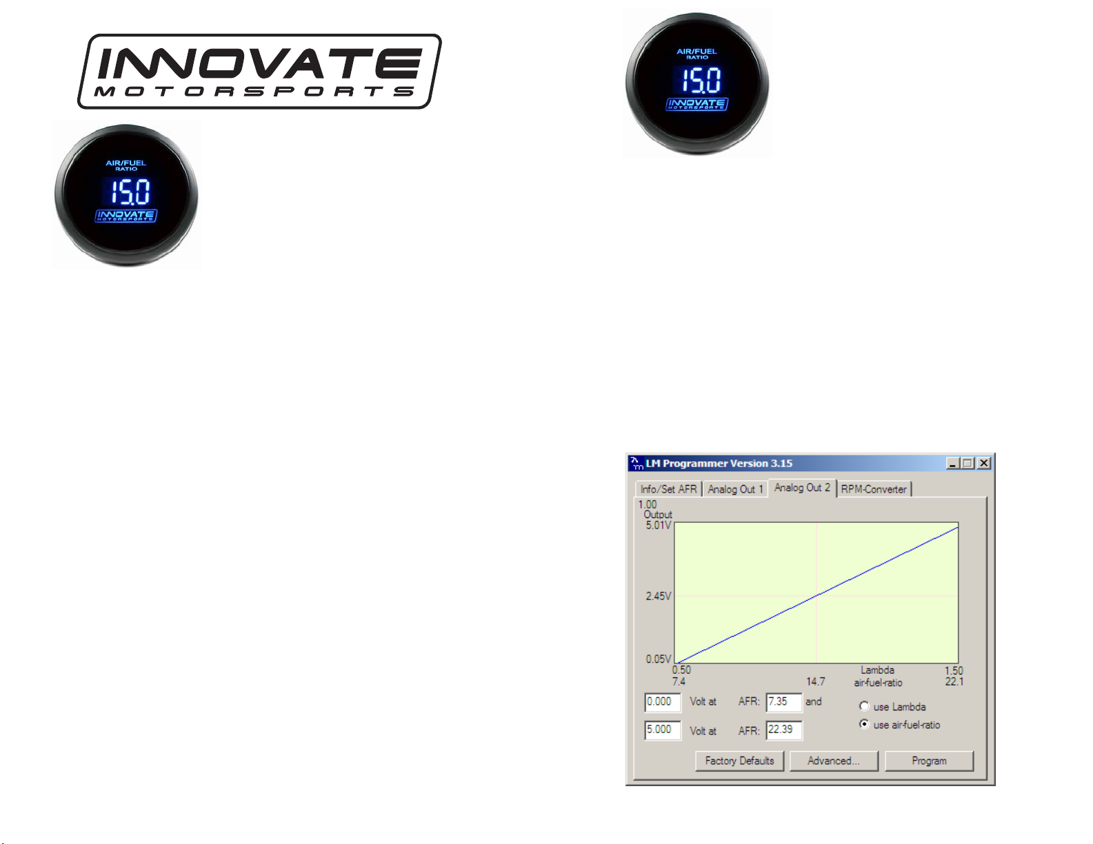
4. Connect the gauge’s WHITE wire to the LC-1’s Brown
analog output 2. The gauge is setup to work with the LC-1’s
analog output 2 factory default setting of 0v = 7.35 A/F and
5v = 22.39 A/F.
5. Connect the YELLOW wire to a headlight power wire (a
wire that supplies current to the headlights). This enables the
display to dim for better nighttime viewing. DO NOT
CONNECT THIS WIRE TO THE HEADLIGHT DIMMING
WIRE. Connection to this rheostat type of switch will cause
the gauge to malfunction. If you chose not to utilize the
dimming feature, connect the yellow wire to ground.
Optional Tip/Trick (requires connection of LC-1 to PC)
The LC-1 can be programmed to output specific voltages during
warm-up and error conditions. This can be done by connecting
the LC-1 to the computer and launching LM Programmer. The
warm-up and error condition options for the analog output are
under the Advanced… settings. For example, if you setup the
error condition at 5V your gauge will display full lean if any
problem arises. Please refer to chapter 6.5.1 in the LC-1 manual
for further information.
DB Digital Air/Fuel Gauge
(with Innovate Motorsports text)
LM-1/LM-2 Quick Start Guide
1. Connect the gauge’s RED wire to a switched 12 volt source
(ignition switched).
2. Connect the gauge’s BLACK ground wire and the LM-1’s or LM-
2’s corresponding analog ground to a solid ground point.
3. Connect the gauge’s WHITE wire to the white analog output wire
if you have an LM-1 or to the lime green wire if you have an LM-2.
4. Connect the YELLOW wire to a headlight power wire (a wire that
supplies current to the headlights). This enables the display to for
better nighttime viewing. DO NOT CONNECT THIS WIRE TO
THE HEADLIGHT DIMMING WIRE. Connection to this rheostat
type of switch will cause the gauge to malfunction. If you chose not
to utilize the dimming feature, connect the yellow wire to ground.
5. ONLY LM-1 users: Connect the LM-1 to the computer and
launch LM Programmer. Setup the analog output 2 and configure it
as 0v = 7.35 A/F and 5v = 22.39 A/F. Lastly click on the “Program”
button.

DB Digital Air/Fuel Gauge
(Wide-Band Air/Fuel text)
LC-1 Quick Start Guide
1. Wire the LC-1 per the unit’s instructions
2. Connect the gauge’s RED wire to a switched 12 volt source
(ignition switched).
3. Connect the gauge’s BLACK ground wire at the LC-1’s
White ground point. This ground point should ideally be an
engine block ground.
4. Connect the gauge’s BLUE wire to the LC-1’s Brown analog
output 2. The gauge is setup to work with the LC-1’s analog
output 2 factory default setting of 0v = 7.35 A/F and 5v =
22.39 A/F.
5. Connect the PURPLE wire to a headlight power wire (a wire
that supplies current to the headlights). This enables the
display to dim for better nighttime viewing. DO NOT
CONNECT THIS WIRE TO THE HEADLIGHT DIMMING
WIRE. Connection to this rheostat type of switch will cause
the gauge to malfunction. If you chose not to utilize the
dimming feature, connect the purple wire to ground.
Optional Tip/Trick (requires connection of LC-1 to PC)
The LC-1 can be programmed to output specific voltages during
warm-up and error conditions. This can be done by connecting
the LC-1 to the computer and launching LM Programmer. The
warm-up and error condition options for the analog output are
under the Advanced… settings. For example, if you setup the
error condition at 5V your gauge will display full lean if any
problem arises. Please refer to chapter 6.5.1 in the LC-1 manual
for further information.
DB Digital Air/Fuel Gauge
(Wide-Band Air/Fuel text)
LM-1/LM-2 Quick Start Guide
1. Connect the gauge’s RED wire to a switched 12 volt source
(ignition switched).
2. Connect the gauge’s BLACK ground wire and the LM-1’s or LM-
2’s corresponding analog ground to a solid ground point.
3. Connect the gauge’s BLUE wire to the white analog output wire if
you have an LM-1 or to the lime green wire if you have an LM-2.
4. Connect the PURPLE wire to a headlight power wire (a wire that
supplies current to the headlights). This enables the display to for
better nighttime viewing. DO NOT CONNECT THIS WIRE TO
THE HEADLIGHT DIMMING WIRE. Connection to this rheostat
type of switch will cause the gauge to malfunction. If you chose not
to utilize the dimming feature, connect the purple wire to ground.
5. ONLY LM-1 users: Connect the LM-1 to the computer and
launch LM Programmer. Setup the analog output 2 and configure it
as 0v = 7.35 A/F and 5v = 22.39 A/F. Lastly click on the “Program”
button.
Other manuals for LC-1
3
This manual suits for next models
2
Other Innovate Motorsports Controllers manuals


