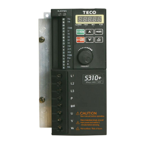
TECO E310 Series User manual

Microprocessor Controlled
I G B T Drive
Inverter Motor Speed Regulator
Operating Manual
E310 Series
200V class
400V class
0.4~1.5KW
(1.2~2.9KVA)
0.75~3.7KW
(1.7~6.7KVA)

i
E310 Table of Contents
Chapter 0Preface 0-1
0.1 Preface 0-1
0.2 Product Inspection 0-1
Chapter 1 Safety Precautions 1-1
1.1 Operation Precautions 1-1
1.1.1 Before Power UP 1-1
1.1.2 During Power UP 1-2
1.1.3 Before Operation 1-2
1.1.4 During Operation 1-3
1.1.5 During Maintenance 1-3
Chapter 2 Definition of Model 2-1
Chapter 3 Ambient Environment and Installation 3-1
3.1 Environment 3-1
3.2 Environmental Precautions 3-2
3.3 Electrical Installation 3-3
3.3.1 Wiring guidelines 3-3
3.3.2 Contactor and Circuit Breaker specification and wiring 3-4
3.3.3 Precautions for Peripheral Applications 3-5
3.4 Specifications 3-8
3.4.1 Product Specifications 3-8
3.4.2 General Specifications 3-9
3.5 Wiring Diagram E310 Series Inverter 3-11
3.6 Description of connection terminals 3-12
3.7 Outline Dimension 3-13
Chapter 4 Software Index 4-1
4.1 Keypad Description 4-1
4.1.1 Keypad Display and Operation Instruction 4-1
4.1.2 Operation Instruction of the LED keypad 4-2
4.2 Control Mode Selection 4-3
4.3 E310 Programmable Functions List 4-4
4.4 Parameter Function Description 4-17
Chapter 5 Troubleshooting and Maintenance 5-1
5.1 Error Display and Corrective Action 5-1
5.1.1 Faults which can not be recovered manually 5-1
5.1.2 Special conditions 5-2
5.1.3 Operation errors 5-3
5.2 General Troubleshooting 5-4
5.3 Quick Troubleshooting of E310 5-5
5.4 Routine and periodic inspection 5-11
5.5 Maintenance and Inspection 5-12
Chapter 6 Peripheral Components 6-1
6.1 Reactor Specification at Input Side 6-1
6.2 Braking unit and braking Resistor 6-1
6.3 Digital operator and extension cable 6-2
AppendixⅠE310 Parameters Setting List App1

ii
Index of Figures
Figure 2-1 Inverter Nameplate.....................................................................................2-1
Figure 3-1 Panel and enclosure arrangement for E310 inverters...................................3-1
Figure 3-2 Din rail mounting of the E310 inverter........................................................3-1
Figure 3-3 Typical Installation Schematic.....................................................................3-5
Figure 3-4a) Installation Examples...............................................................................3-6
b) Installation Examples Using a Filter and Isolation transformer................3-6
c) Installation Examples with Adjacent Signal Conductors...........................3-6
Figure 3-5 Control Cable requirements........................................................................3-7
Figure 3-6 Grounding Examples ..................................................................................3-7
Figure 3-7 Wiring Diagram..........................................................................................3-11
Figure 3-8 Frame size 1 Dimensions.............................................................................3-13
Figure 3-9 Frame size 2 Dimensions.............................................................................3-14
Figure 4-1 Keypad Layout ...........................................................................................4-1
Figure 4-2 LED Keypad Operations Sequence..............................................................4-2
Figure 4-3 Control Mode Selection Chart.....................................................................4-3
Figure 4-4 Frequency reference limits..........................................................................4-18
Figure 4-5 Terminal Board Drive Operation Modes .....................................................4-19
Figure 4-6 3-Wires Start/Stop Wiring...........................................................................4-19
Figure 4-7 Drive Start/Stop Operation sequences .........................................................4-20
Figure 4-8 Acceleration and deceleration Prohibit........................................................4-22
Figure 4-9 UP/DOWN original mode example..............................................................4-24
Figure 4-10 UP/DOWN with incremental steps.............................................................4-24
Figure 4-11 Frequency reached example ......................................................................4-25
Figure 4-12Frequency within specified range example..................................................4-26
Figure 4-13 Frequency outside of range example..........................................................4-26
Figure 4-14 Frequency at or below specified range example..........................................4-27
Figure 4-15 Over torque detection example..................................................................4-27
Figure 4-16 Analog scaling examples ...........................................................................4-29
Figure 4-17 Multifunction analog output......................................................................4-30
Figure 4-18 KEB function diagram ..............................................................................4-34
Figure 4-19 DC Injection Braking Example..................................................................4-35
Figure 4-20 Custom V/F settings ..................................................................................4-35
Figure 4-21 Custom V/F Patterns.................................................................................4-36
Figure 4-22 V/F curve with torque boost ......................................................................4-37
Figure 4-23 Output Torque Capacity ..........................................................................4-38
Figure 4-24 Slip Compensation ....................................................................................4-39
Figure 4-25 Low Frequency Voltage Compensation......................................................4-39

iii
Figure 4-26 PID block diagram....................................................................................4-43
Figure 4-27 PID sleep wake mode diagram...................................................................4-45
Figure 4-28 S-Curve Characteristics ............................................................................4-47
Figure 4-29 Single cycle auto run .................................................................................4-51
Figure 4-30 Periodic cycle auto run..............................................................................4-52
Figure 4-31 Single cycle auto run: final step hold..........................................................4-52
Figure 4-32 AUTO_RUN cycle with interrupt .............................................................4-53
Figure 5-1 E310 Fault Display and Troubleshooting Flow Chart...................................5-6
Figure 5-2 OC, OL Fault Display Flow Chart...............................................................5-7
Figure 5-3 OV, LV Fault Display Flow Chart ..............................................................5-8
Figure 5-4 Motor RUN failure Flow chart ...................................................................5-9
Figure 5-5 Motor Overheat Troubleshooting Flow Chart..............................................5-10
Figure 5-6 Motor Instability Troubleshooting Flow Chart............................................5-10
Figure 6-1 Digital Operator Extension Cable................................................................6-2

0-1
Chapter 0 Preface
0.1 Preface
To extend the performance of the product and ensure personnel safety, please read this manual
thoroughly before using the inverter. Should there be any problem in using the product that
cannot be solved with the information provided in the manual, contact your nearest Taian’s
technical or sales representative who will be willing to help you.
※Precautions
The inverter is an electrical product. For your safety, there are symbols such as “Danger”,
“Caution” in this manual as a reminder to pay attention to safety instructions on handling,
installing, operating, and checking the inverter. Be sure to follow the instructions for highest
safety.
Danger Indicates a potential hazard that could cause death or serious personal injury if
misused.
Caution Indicates that the inverter or the mechanical system might be damaged if
misused.
Danger
zDo not touch any circuit boards or components after the power is turned off and while the
charging indicator is still lit. (The light will fade)
zDo not make any connections when the inverter is powered on. Do not check parts and
signals on circuit boards during the inverter operation.
zDo not disassemble the inverter or modify any internal wires, circuits, or parts.
zGround the ground terminal of the inverter properly.
For 200V class ground resistance 100 Ωor below. For 400V class 10Ωor below.
Make sure that grounding conductors are adequately sized and are according to your
local safety regulations.
Caution
zDo not perform a voltage test on parts inside the inverter. High voltage can destroy the
semiconductor components.
zDo not connect T1, T2, and T3 terminals of the inverter to any AC input power supply.
zCMOS ICs on the inverter’s main board are susceptible to static electricity. Do not touch
the main circuit board
0.2 Product Inspection
Taian inverters have all passed the function test before delivery. Please check the following
when you receive and unpack the inverter:
zThe model of the inverter are the same as those specified in your purchase order.
zCheck for any damages caused by transportation. Please do not apply power, and
contact a Taian sales representative if any of the above problems occurred.

1-1
Chapter 1 Safety Precautions
1.1 Operation Precautions
1.1.1. BeforePowerUp
Caution
The line voltage applied must comply with the inverter’s specified input voltage.(See
product nameplate)
Danger
Make sure the main circuit connections are correct. L1, L2 and L3 are power-input
terminals and must not be mistaken for T1, T2 and T3. Otherwise, inverter damage can
result.
Caution
To avoid the front cover from disengaging or other damage, do not carry the inverter by
its cover. Support the drive by its heat sink when transporting. Improper handling can
damage the inverter or injure personnel, and should be avoided.
To avoid the risk of fire, do not install the inverter on flammable objects. Install on
nonflammable objects such as metal surfaces.
If several inverters are placed in the same control panel, provide heat extraction means
to keep the temperature below 40℃to avoid overheat or fire hazard.
When removing or installing the operator keypad, turn OFF the power first, and secure
the keypad correctly to avoid keypad operation or display failure.
Warning
This product is sold subject to IEC 61800-3. In a domestic environment this product
may cause radio interference in which case the user may be required to apply corrective
measures.
Motor over temperature protection is not provided.

1-2
1.1.2. DuringPowerUp
Danger
zDo not insert or remove input connections to the inverter when powered up to avoid
damage to the control board resulting from possible voltage surge due to contact
bounce.
zWhen momentary power loss is longer than 2 seconds (the larger of horse power, the
longer of time), the inverter does not have enough storage power to control the circuit;
Therefore, when the power is re-applied, the operation of the inverter is based on the
setup of 00-03(or00-04) /04-09 and the condition of external switch, this is considered
to be「restart」in the following paragraphs.
zWhen the momentary power loss is short, the inverter still has enough storage power to
control the circuit. Therefore, when power is re-applied, the inverter will automatically
restart depending on the setup of 04-03/04-04.
zWhen restarting the inverter, the operation of the inverter is based on the setup of 00-
03(or00-04) and 04-09 and the condition of external switch (FWD/REV button).
Attention: the start operation will be regardless of 04-03/04-04/04-06/04-07.
1. When 00-03(or00-04) =0, the inverter will not automatically run after restart.
2. When 00-03(or00-04) =1 and the external switch is OFF, the inverter will not run
after restart.
3. When 00-03(or00-04) =1, the external switch is ON, and 04-09=0, the inverter will
run automatically after restart.
Attention: To ensure safety, please turn off the external switch (FWD/REV button)
after power loss, to protect machines from possible damage and potential injury to
personnel on sudden resumption of power.
zIf 4-09 is set to 0 (direct start up), please refer to the description and warnings for 04-09
to verify the safety of operator and machine.
1.1.3. BeforeOperation
Danger
Make sure the model and inverter capacity are the same as that set in parameter 12-00.
Caution
On power up the supply voltage set in parameter 05-03 will flash on display for 2 seconds.

1-3
1.1.4. DuringOperation
Danger
Do not connect or disconnect the motor during operation. Otherwise, the over-current will
cause the inverter to trip or damage the unit.
Danger
zTo avoid electric shock, do not take the front cover off when power is on.
zThe motor will restart automatically after stop when auto-restart function is on. In this
case, use caution while working near the drive, motor, or driven equipment.
zNote: The stop push button and external stop command have no safety function.
For Emergency stop, it is necessary to use a correct latch type push button and an
appropriate circuit or devices to ensure safety.
Caution
zDo not touch heat-generating components such as heat sinks and braking resistors.
zThe inverter can drive the motor from low speed to high speed. Verify the allowable
speed range of the motor and the load before operation.
zNote the settings related to the braking unit.
zDo not check signals on circuit boards while the inverter is running.
Caution
Allow 5 minutes after disconnecting power before disassembling or checking the
components. The power led should not be illuminated.
1.1.5. During Maintenance
Caution
The Inverter can be used in a non-condensing environment in temperature range from
14˚-104 (℉-10-40 )℃and relative humidity of 95%
Inverter Disposal
Caution
zPlease dispose of this unit with care as an industrial waste and according to your
required local regulations.
zThe capacitors of inverter main circuit and printed circuit board are considered as
hazardous waste and must not be burnt.
zThe Plastic enclosure and parts of the inverter such as the top cover board will release
harmful gases if burnt.

2-1
Chapter 2 Definition of model
200~240V 50/60Hz
Output specifications→
1.7 KVA 4.5 A
TECO Electric & Machinery co., Ltd.
E310Series:
E31 0 - 2 01 - H
Supply voltage Specification
2 200Vclass H
4 400Vclass
Adhibition Horsepower
0 standard Type P5 0.5 HP
01 1 HP
02 2 HP
03 3 HP Power supply
05 5 HP
3
Three phase
Blank
c
ommon model
f
or single /Three
p
hase
MODEL: E310-201-H
Inverter model →
I/P: AC 1 OR 3PH
In
p
ut volta
g
e →
O/P: AC 3PH 0~240V
Figure 2-1 Inverter Nameplate

3-1
Chapter 3 Ambient Environment and Installation
3.1 Environment
The environment will directly affect the proper operation and the life span of the inverter, so install
the inverter in an environment complying with the following conditions:
(Correct configuration) (Incorrect configuration) (Correct configuration) (Incorrect configuration)
Place the inverter facing forward and its top facing upward to assist with cooling.
73000CV
Installing
direction
5cm5cm
12cm 12cm
5cm
Ambient temperature: 14-104℉(-10oC - +40oC)
Avoid exposure to rain or moisture. Avoid direct sunlight.
Avoid oil mist and salinity. Avoid corrosive liquid and gas.
Avoid dust, lint fibers, and small metal
filings.
Keep away from radioactive and
flammable materials.
Avoid electromagnetic interference (soldering machine, power machine).
Avoid vibration (stamping, punching machine). Add a vibration-proof pad if the situation
cannot be avoided.
If several inverters are placed in the same control panel, provide heat removal means to
maintain temperatures below 40oC.
CONTROL
PANEL
CONTROL
PANEL Enclosure
Fan
Fan
Figure 3-1 Panel and enclosure arrangement for E310 inverters
Enclosure
Figure 3-2 Din rail mounting of the E310 Inverter
E310 E310
E310
E310
E310
Air convection
-10oC - +40oC
(a) Front view (b) Side view

3-2
3.2 Environmental precautions
Do not use the inverter in an environment with the following conditions:

3-3
3.3 Electrical Installation
3.3.1 Wiring guidelines
A. Power Cables
Power cables are connected to TM1 terminal block, terminals L1, L2, L3, T1, T2, T3, P, R.
Choose power cables according to the following criteria:
(1)Use copper wires only. Correct wire diameters should be based on ratings at 105oC.
(2)For rating voltage of wires, the minimum voltage of 200V class type is 300V, and 400 V class
type is 600V.
B. Control Cables
Control cables are connected toTM2 control terminal block.
Choose control cables according to the following criteria:
(1) Use copper wires only. Correct wire diameters should be based on ratings at 105oC.
(2) For rating voltage of wires, the minimum voltage of 200V class type is 300V, and 400 V class
type is 600V.
(3) To avoid noise interference, do not route power and control cables in the same conduit or
trucking.
(4) Where possible use screened / shielded control cables to minimizes electromagnetic
interference.
(5) To avoid ground loops always earth the shield of control cables at one end only.
C. Nominal electrical specifications of the terminal Block TM1:
※Note: Nominal values of input and output signals (TM2,TM3) – follow the specifications of
class 2 wiring.
D. Fuse types
Drive input fuses are provided to disconnect the drive from power in the event that a component
fails in the drive’s power circuitry. The drive’s electronic protection circuitry is designed to clear
drive output short circuits and ground faults without blowing the drive input fuses. Table below
shows the E310 input fuse ratings.
To protect the inverter most effectively, use fuses with current-limit function.
Horsepower power supply standard Fuse types
1/2 200-240V 15A, 600VAC, 100KA I.R.
1
380-480V
5A, 600VAC, 100KA I.R.
2 10A, 600VAC, 100KA I.R.
3 15A, 600VAC, 100KA I.R.
5 20A, 600VAC, 100KA I.R.
※Notice
To avoid shock hazards, do not touch any electrical component when the power is applied or
with in five minutes after the power is disconnected. Any inspection should be performed after
the charge indicator goes off.
Do not perform wiring on the inverter with power on. Disregard of this notice may result in
serious injury.
Horsepower Power source Amps Volts
0.5/1/ 2 200-240V 15 6001/ 2 380-480V
3/ 5 380-480V 40

3-4
3.3.2 Contactor and Circuit Breaker specification and wiring.
Molded-case circuit breaker/magnetic contactor
Teco bears no responsibility to service for failures caused by the following conditions:
(1) A molded-case circuit breaker is not installed, or an improper or overrated breaker is used,
between the power source and the inverter.
(2) A magnetic contactor, a phase capacitor, or a burst absorber is connected between the
inverter and the motor.
model:
E310-□□□-XXX 2P5 201 202
Molded-case circuit
breaker made by Teco
50E
10A
50E
20A
50E
30A
Magnetic contactor
(MC) made by Teco
CN-11
Main circuit terminals
(TM1)
Wire gauge 2.0 mm2
terminal screw M3.5
Signal terminals
(TM2,TM3)
Wire gauge 0.80mm2 ( # 18 AWG)
terminal screw M3
model:
E310-□□□-XXX 401/402/403/405
Molded-case circuit
breaker made by Teco 50E 15A
Magnetic contactor
(MC) made by Teco CN-11
Main circuit terminals
(TM1)
Wire gauge 2.0 mm2
terminal screw M3.5
Signal terminals
(TM2,TM3)
Wire gauge 0.80mm2 ( # 18 AWG)
terminal screw M3
Use three-phase squirrel cage induction motor with capacity suitable for the inverter.
If one inverter is driving several motors, the total current of all motors running simultaneously
must be less than the rated current of the inverter, and each motor has to be equipped with a
proper thermal relay.
Do not add capacitive components, such as a phase capacitors, LC or RC, between the inverter
and the motor.

3-5
3.3.3 Precautions for peripheral applications:
Power supply:
Make sure the correct voltage is applied to avoid
damaging the inverter.
A molded-case circuit breaker or fused disconnect
must be installed between the AC source and the
inverter
Molded-case circuit breaker:
Use a molded-case circuit breaker that conforms to the
rated voltage and current of the inverter to control the
power ON/OFF and protect the inverter.
Do not use the circuit breaker as the run/stop switch
for the inverter.
Leakage breaker:
Install a leakage breaker to prevent problems caused
by electric leakage and to protect personnel.
Setting current should be 200mA or above and the
operating time at 0.1 second or longer to prevent
malfunctions.
Magnetic contactor:
Normal operations do not need a magnetic contactor.
However a contactor has to be installed in primary
side when performing functions such as external
control and auto restart after power failure, or when
using a brake controller.
Do not use the magnetic contactor as the run/stop
switch of the inverter.
AC reactor for power quality improvement:
When inverters below 200V/400V class 15KW are
supplied with high capacity (above 600KVA) power
source or an AC reactor can be connected to improve
the power performance.
Install fast action fuse:
To ensure the safety of peripheral devices, please
install fast action fuse. Regarding the specification,
please refer to P3-3.
Input noise filter:
A filter must be installed when there are inductive
loads affecting the inverter
Inverter:
Input power terminals L1, L2, and L3 can be used in
any sequence regardless of phase.
Output terminals T1, T2, and T3 are connected to U,
V, and W terminals of the motor. If the motor is
reversed while the inverter is set to run forward, just
swap any two terminals of T1, T2, and T3.
To avoid damaging the inverter, do not connect the
input terminals T1, T2, and T3 to AC input power.
Connect the ground terminal properly. 200V class:
class 3 grounding, <100; 400V class : <10.
Figure 3-3 Typical Installation Schematic
E310
Ground
AC reactor
for power
improvement
Three-phase
cage motor
Ground
Input noise
filter
Magnetic
contactor
Molded-case
circuit breaker
INVERTER
Power

3-6
Make external connections according to the following instruction. Check connections after wiring
to make sure all connections are correct. (Do not use the control circuit buzzer to check connections)
(A) Main circuit’s wiring must be separated from other high voltage or high current power line to
avoid noise interference. Refer to the figures below:
A general noise filter may not provide correct resultsThe inverter uses dedicated power line
~
General
noise
filter
~General
noise
filter
Add a noise filter or separation transformer when
sharing the power line with other machines.
The inverter shares the power line with other machines
A noise filter in the output of the main circuit can suppress conducted noise.
To prevent radiated noise, the wires should be put in a metal pipe and distance from signal
lines of other control equipment should be more than 30 cm.
Power Supply
MCCB
N
o
i
se
Filter
Metal Box
Metal Pipe
Signal Wire
Controller
30 cm above
E310 Noise
Filter
Figure 3-4a) Installation Examples
Figure 3-4b) Installation Examples using a filter and Isolation transformer
Figure 3-4c) Installation Examples with Adjacent Signal Conductors

3-7
When the connection between the inverter and the motor is too long,consider the voltage
drop of the cables. Phase-to-phase voltage drop (V) =
3 ×resistance of wire (Ω/km)×length of line (m)×current×10-3.
Carrier frequency must be adjusted based on the motor cable length.
Cable length
b
etween the inverter and
the motor Below 150ft Below 300ft Above 300ft
Recommended
carrier frequency Below 12KHz Below 8KHz Below 5KHz
Setting of parameter 10-03 12 8 5
(B) The control circuit wiring must be separated and routed away from the main circuit control line
or other high voltage or current power lines to avoid noise interference
●To avoid erroneous operation caused by noise interference, shield the control circuit wiring
with twisted-wires, and connect the shielded wire to a ground terminal. Refer to the figure below.
The wiring distance should not exceed 50 meters.
(C)Inverter Ground terminal must be connected to installation ground correctly and according to
the required local wiring regulations.
For 200V class ground resistance should be 100Ωor less.
For 400V class ground resistance should be 10Ωor less.
●Ground cable size must be according to the required local wiring regulations. The shorter the
better.
●Do not share the ground of the inverter with other high current loads
(Welding machine, high power motor). Connect the terminals to their own ground.
●Do not make a loop when several inverters share a common ground point.
E310 E310 E310 E310 E310 E310 E310 E310 E310
(a) Good (b) Good (c) Bad
(D) To ensure maximum safety, use correct wire size for the main power circuit and control circuit.
(According to the required local regulations)
(E) Verify that all wiring is correct, wires are intact, and terminal screws are secured.
Shielding sheath Protective coverin
g
To ground terminal
Wrapped with insulating tape
Do not connect this en
d
Figure 3-5 Control Cable requirements
Figure 3-6 Grounding Examples

3-8
3.4 Specifications
3.4.1 Product Specifications
Single / Three phase, 200-240V model
Model: E310-□□□-XXX 2P5 201 202
Horsepower(HP) 0.5 1 2
Max Applicable Motor Output
(KW) 0.4 0.75 1.5
Rated Output Current(A) 3.1 4.5 7.5
Rated Capacity(KVA) 1.2 1.7 2.9
Max Applicable Motor Output
(KW) Single/Three Phase: 200~240V +10% -15%, 50/60HZ 5%
Max. Output Voltage Three Phase: 200~240V
Net Weight (KG) 1.37 1.37 1.47
Allowable momentary power loss
time (second) 1.0 1.0 2.0
Three phase, 380 – 480V model
Model:E310-□□□-XXX 401 402 403 405
Horsepower(HP) 1 2 3 5
Max Applicable Motor Output
(KW) 0.75 1.5 2.2 3.7
Rated Output Current(A) 2.3 3.8 5.2 8.8
Rated Capacity(KVA) 1.7 2.9 4.0 6.7
Max Applicable Motor Output
(KW) Three phase:380~480V +10% -15%, 50/60HZ 5%
Max. Output Voltage Three phase : 380~480V
Net Weight (KG) 1.33 1.35 2.22 2.25
Allowable momentary power loss
time (second) 1.0 1.0 2.0 2.0

3-9
3.4.2 General Specifications
Item E310
Control Mode V/F or Vector Control
Frequency Control
Range 0.01~400.00 Hz
Start control torque 150%/1Hz ( Vector)
Speed control range 1:100 ( Vector)
Speed Control Precision ±0.5% (Vector)
Setting resolution Digital: 0.01Hz, Analog: 0.06Hz/ 60Hz(10bits)
Keypad setting Set directly with▲▼ keys or the VR on the keypad
Display Function
Five digital LED and status indicator; display frequency/ line
speed/ DC voltage/ Output voltage/ Current/ Rotation direction/
Inverter parameter/ Fault Log/ Program Version / Heat sink
temperature/PID feed back
External signal setting
1. External potentiometer0-10V/ 0-20mA
2. Provides up/down controls, speed control or automatic
procedure control with multifunctional contacts on the terminal
block (TM2)
Frequency Limit
Function
Upper/lower frequency limits and three programmable skip
frequencies
Carrier frequency 1 ~ 12 kHz
V/F pattern 18 fixed patterns, 1programable curve
Acc/Dec control Two-stage Acc/Dec time (0.1 – 3,600 seconds) and four-stage S
curves (refer to descriptions on 10-07.)
Multifunction analog
output 5 functions (refer to description on 2-12)
Multifunction input 22 functions (refer to description on 01-00~01-05)
Multifunction output 14 functions (refer to description on 01-09~01-10)
Other Functions
Momentary Power Loss Restart, Speed Search, Overload
Detection, 8 preset speeds. Acc/Dec Switch (2 Stages), S Curves,
3-wire Control, PID control, torque boost, Slip Compensation,
Frequency Upper/ Lower Limit, Auto energy saving, Modbus
slave and PC/PDA Link, Auto Restart, Encoder input.

3-10
Item E310
Communication Control
1. Control by RS485
2. One to one or one to many control.
3. BAUD RATE/STOP BIT/PARITY/bit can be set
Braking Torque
About 20﹪, the model below 20HP with built-in braking
transistor and the specified external braking resistors can provide
100%
Operation temperature 14-120℉(-10 ~ 50℃)
Storage temperature 4-140℉(-20 ~ 60℃)
Humidity 0 – 95% Relative Humidity(Non-condense)
Vibration 1G (9.8m/ 2
S)
Enclosure IP20
Protective Functions
Overload protection The relays to protect the motor (the curve can be set) and the
inverter (150 % / 1min)
Over Voltage 200V class: DC Voltage>410V 400Vclass: DC Voltage>820V
Under Voltage 200V class: DC Voltage<190V 400Vclass: DC Voltage<380V
Momentary Power
Loss Restart
Restart can be initiated with spin start after momentary power loss
in Max 2 sec.
Stall Prevention Stall prevention for Acceleration/ Deceleration/ Operation.
Short-circuit output
terminal
Electronic Circuit Protection
Grounding Fault Electronic Circuit Protection
Other Function
Protection for overheating of heat sink, over torque detection,
error contact control, reverse prohibit, prohibit for direct start
after power up and error recovery, parameter lock up.

3-11
3.5 Wiring diagram E310 series inverter
( ( (
Figure 3-7 Wiring Diagram
Note 1: Please refer to description of main circuit terminals (P, R) and specification of braking
resistor for value selection.
2: please avoid connecting output of inverter to the earth.
3: RS-485 (RJ45)
CON2
RY1
TR1
1
8
1: A′2: B′3: A′
4: R 5: D 6: B′
7:DP5V 8:SG(GND)
This manual suits for next models
1
Table of contents
Other TECO Controllers manuals