Innovate 9500 User manual
496332 Issue 1 1 of 22
9500
Installation and User Guide
Compatible Equipment
9525 Remote Keypad
9505 LIM
9507 LIM + PSU
9508 Shunt LIM (4 zones)
9509 Shunt LIM Controller
9510 EOL LIM (3 Zones)
9585 Engineers Printer (Centronics)
9589 Printer lead (Centronics)
9590 Hardware Mimic System
9597 Computer Mimic System
2 of 22 496332 Issue 1
Introduction
The 9500 Series System is a fully programmable, microprocessor controlled,
electronic intruder alarm system designed to meet the security requirements
of medium to large industrial and commercial premises.
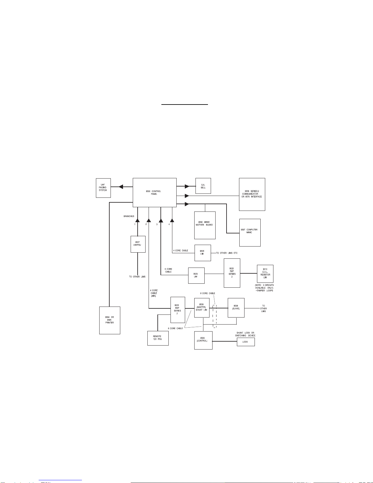
The system operates on the “Multiplex” principle using four main data high-
ways (or branches) from the main control panel. Each branch comprises a
minimum 4-core cable, (6-core where keypads are included in branch), which
may be up to 2km (2000 metres) in length and may accommodate a combi-
nation of up to 16 Line Interface Modules (LIMs), Remote Keypads and
Isolation LIMs.
Figure 1. System Configuration
Each Line Interface Module has five double-pole circuits which can individu-
ally be programmed to any one of six circuit types and can feature any or all
9500

496332 Issue 1 3 of 22
of the seven circuit attributes, (Attributes do not apply to P.A., Technical
Alarm or 24 hour circuits).
The main control panel is provided with outputs suitable for connection to a
printer or a completely programmed mimic diagram system. The system will
accept a plug-in digital communicator (fast format only) or a direct-line
interface, which can also be used to connect the Series 9500 to “Red Care”
or “ABC” (Alarms by Carrier).
Technical Specification
Zones 0-320.
Display 32 Character “Supertwist” LCD.
Expansion By line interface modules of up to 5 circuits
per LIM.
BS 4737 Full Specification.
Log 450+ events ( Date andTime ).
Panel Siren No.
Internal Siren 9040 4 max.
Dimensions Panel h x w x d 290 x 400 x 10mm.
Dimensions Keypad h x w x d 180 x 110 x 40mm.
Weight Panel 4.6 Kg, Keypad 500g.
Battery 6 Ah.
Communicator
Output Plug-on STU/ 9058/9056 by using the 9578.
Signalling Conversion Interface.
Plug-on Interface 9576, 9576-01.
Outputs Bell relay contacts,
Strobe relay contacts.
Quiescent Current Ratings
12 Volt Power Quiescent: Panel 165mA, Keypad 50mA.
12 Volt AUX Output Not available unless detector power.
requirement less than 150 mA.
9500 Control Panel 165mA.
9558 Communicator 10mA.
9525 Remote Keypad 50mA.
9505 Standard LIM 10mA.
9506 Bare LIM 10mA.
9510 End Of Line LIM 10mA.
9508 Shunt LIM 10mA.
9509 Controller 12mA.
9500 Technical Specification
4 of 22 496332 Issue 1
Wiring
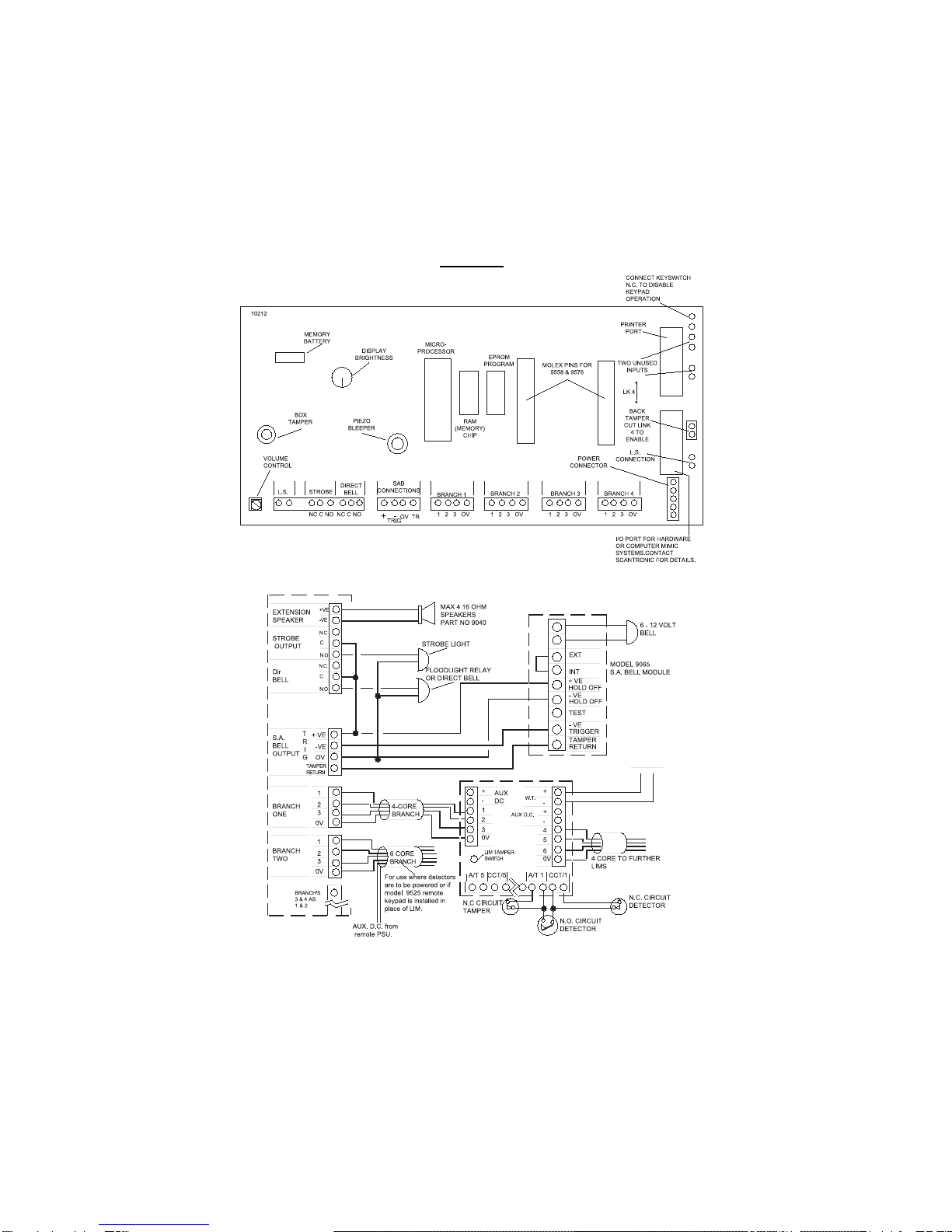
Figure 2. Main PCB Layout
Figure 3. Main PCB Connections
9500

496332 Issue 1 5 of 22
Figure 4. Standard LIM PCB
Figure 5. Connection of Shunt LIM as Single Shunt
9500 Wiring

6 of 22 496332 Issue 1
Figure 6. Connection of Shunt LIM as Multiple Shunt
Figure 7. Connection of End of Line Resistor LIM
Wiring 9500
496332 Issue 1 7 of 22
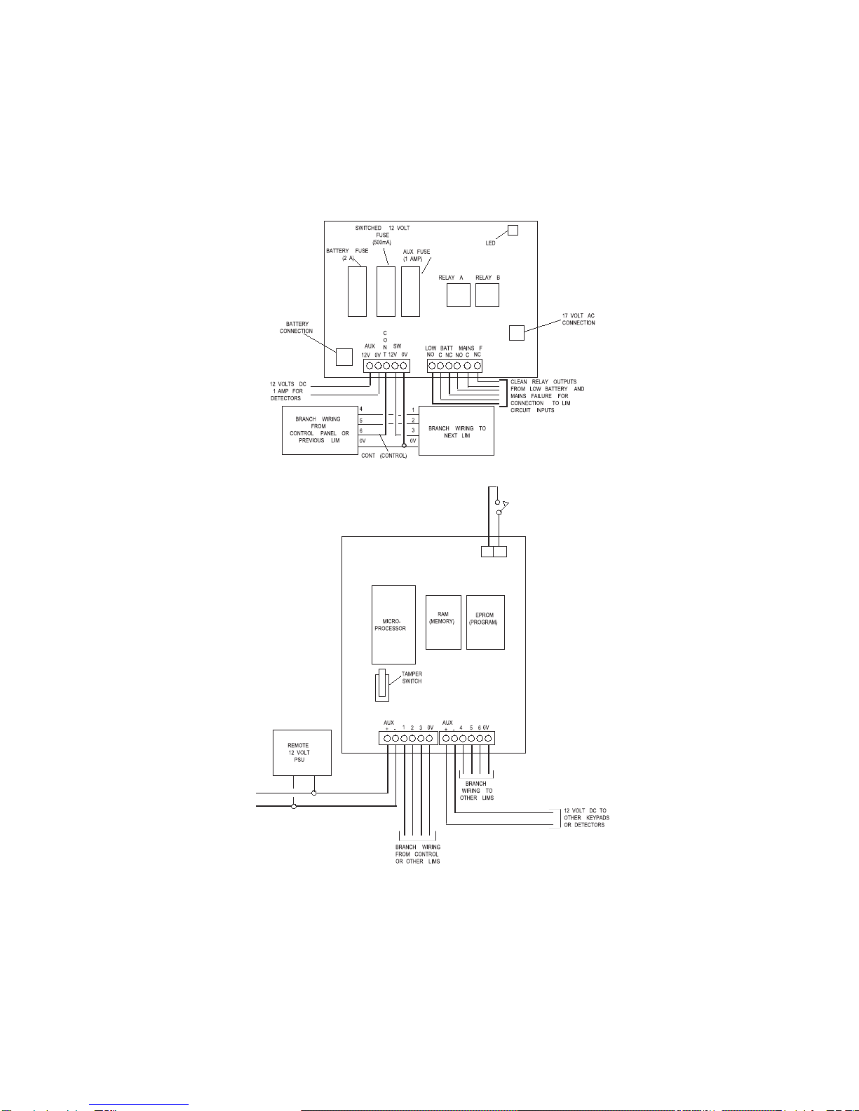
Figure 8. Remote PSU/LIM Layout and Connections
Figure 9. Remote Keypad Connections
9500 Wiring

8 of 22 496332 Issue 1
Figure 10. Wiring the Remote Keypad(s) to the Branch Loops
Figure 11. 9558 Communicator Layout and Connections
Wiring 9500

496332 Issue 1 9 of 22
Figure 12. 9576 Interface Layout
Figure 13. 9576-01 Interface Board Layout
9500 Wiring

10 of 22 496332 Issue 1
Programming
Initial Start Up
Check that all LIM box tampers are closed. Make sure that the Bell and
Strobe is not connected to the main 9500 PCB. Link out any circuits that are
nnot used.
When powering up the panel for the first time:
1. Close the control panel lid and connect the mains supply.
The display shows: <SYSTEM RESET>
12:00 16 OCT 90
Alternatingwith: 12:00 16 OCT 90
Status : Alarm
2. Key in 4567 + Enter.
The display shows: Display
customer log?
3. Press No.
The display shows: <SYSTEM RESET>
12:00 16 OCT 90
Alternatingwith: 16 OCT 12:00:00
CALL ENGINEER
4. Key in 7890 + Enter.
The display shows: Ver 4.20
14 FEB 1991
Followedby: Do you want
engineer reset?
Note: Whenever you enter engineer mode, the software version number and its date
will be displayed. Make a note of this number, as it will be useful when contact-
ing the Scantronic Product Support Department with any queries.
5. Press No.
The display shows: Do you want
test functions?
6. Press No.
The display shows: Do you want
reports?
7. Press No.
The display shows: Do you want to
program the system?
8. Open the control panel lid.
9500

496332 Issue 1 11 of 22
9. Press Yes.
You are now in Engineering Mode.
Defaults
The default Manager 1 Code is 4567 followed by ‘Enter’.
The default Engineer Code is 7890 followed by ‘Enter’.
All circuits are set to Normal Alarm, and not allocated any specific function.
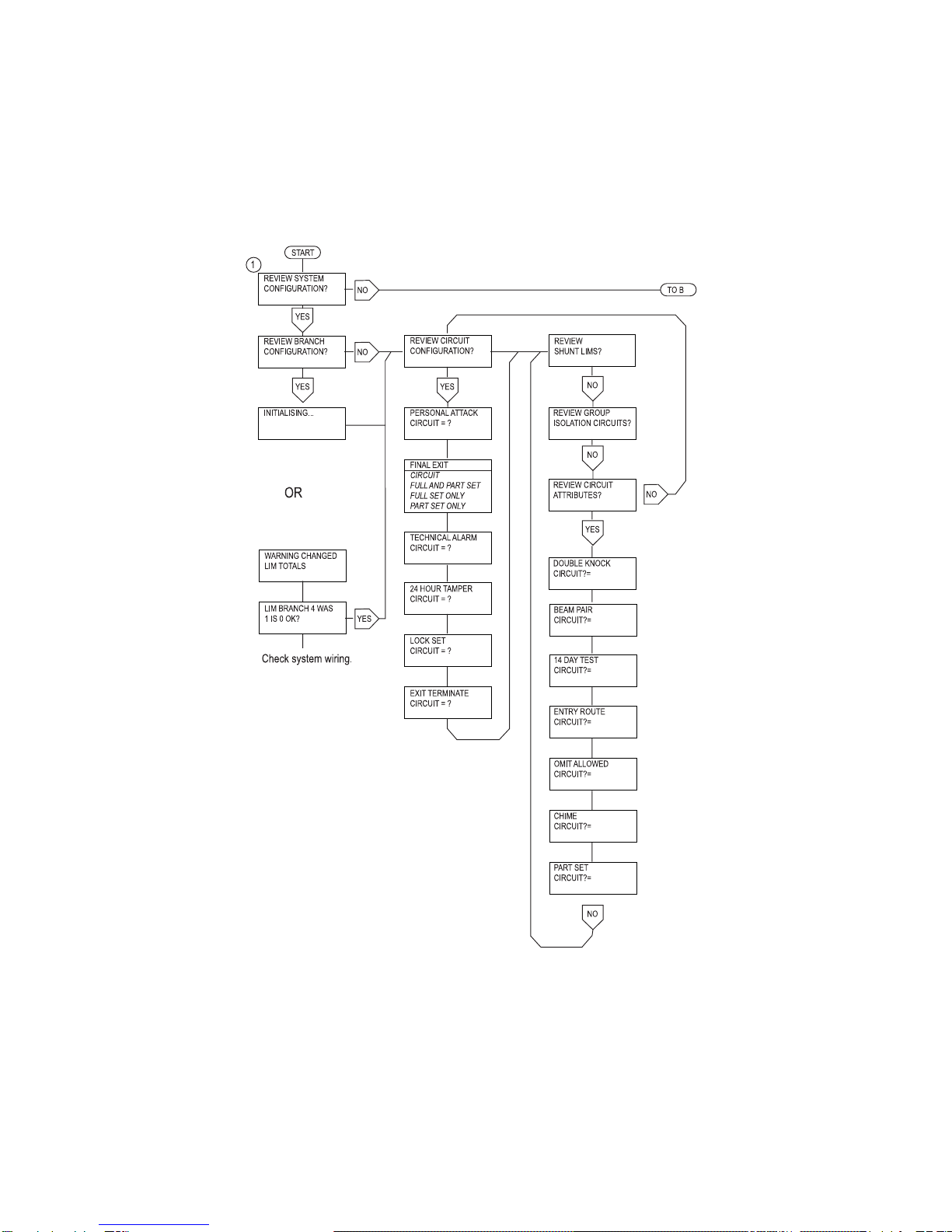
Engineering Program Commands
While programming the system, the control unit shows a series of questions
on the keypad display. Answer the questions by pressing Yes or No on the
keypad. When you respond to a question the control unit will display further
questions in order to lead you through the programming sequence.
In the first stages of programming the system there are a set of numbered
entry points that let you go directly to a specific area of programming. These
numbers are shown in the following table:
Command Keypaddisplay
1 Review system configuration?
2 Review panel controls?
3 Change engineer access code?
4 Review communications?
5 Change site location number?
6 Do you want to set the clock?
7 Do you want test functions?
8 Do you want reports?
9 Do you want engineer reset?
When programming the system for the first time, no circuits are allocated to
specific functions. On entering a function the system asks for a circuit
number. Each circuit has a unique four-digit identification number, made up
of the branch, LIM and circuit number as follows:
1st digit Branch number (1, 2, 3 or 4).
2nd and 3rd digit LIM number (01 to 16). LIMs are numbered in sequence
for each branch. The first LIM on the branch is 01.
4th digit Circuit number (1 to 5).
If you return to a function the display shows the first circuit number of those
you have already programmed. To keep that circuit press “Yes”.
If you want to return a circuit to default programming, call it to the display, key
in “0000”. The system removes that circuit from the display.
The next four pages show the programming commands in more detail.
9500 Engineering Program Commands
12 of 22 496332 Issue 1
Engineering Program Commands 9500

496332 Issue 1 13 of 22
9500 Engineering Program Commands

14 of 22 496332 Issue 1
Engineering Program Commands 9500

496332 Issue 1 15 of 22
Leaving Engineering Mode
Before leaving Engineering Mode, check that the Bell, Strobe, all detectors,
tampers etc., are connected. Also check that the 6.Ah standby battery is
connected and all lids are closed on LIMs, keypads and main control panel.
If your system is fitted with remote signalling, check that it is programmed for
‘Engineer Reset’, and proceed as follows:
The display shows: Do you want to
engineer reset?
1. Press Yes
The display shows: Branch 1
No of LIMs=5
Followedby: Branch 2
No of LIMs=7
Followedby: Branch 3
No of Lims=8
9500 Leaving Engineering Mode

16 of 22 496332 Issue 1
Followedby: Branch 4
No of LIMs=6
Followedby: Total LIMs=26
confirm: yes/no
2. EITHER Press No
The display shows: Review system
configuration
Check for system wiring faults, LIM failures etc.
See "Branch Configuration"
3. OR Press Yes
The display shows: Please wait...
testing system
Followedby: Engineer reset
all circuits OK
Followedby: 26 July 07:46:37
Status:day
You are now in customer day mode.
Re-entering Engineering Mode
1. Key in 7890 + Enter.
The display shows: Ver 4.20
14 FEB 1991
Followedby: Do you want
engineer reset?
2. Press No.
The display shows: Do you want
test functions?
3. Press No.
The display shows: Do you want
reports?
4. Press No.
The display shows: Do you want to
program the system?
5. Open the control panel lid.
6. Press Yes.
You are now in Engineering Mode.
Note: 1. If the system is in operation and has to be powered down (battery & mains)
for servicing, when powering up, the battery must be connected first.This will
Re-entering Engineering Mode 9500

496332 Issue 1 17 of 22
prevent any problems of high current being drawn which could damage the
control panel.
2. The Engineer Reset, Test Functions and Reports can be selected without
opening the control panel lid.
Refreshing The System
If the system requires all the programmed information to be deleted and
returned to the factory de-faults, it is possible to refresh the system in the
followingway.
1. Completely power down the control panel.
2. Remove the RAM chip, which is located on the main PCB and is the
centre of the three large chips.
3. Replace the chip and Power up the control panel. Reset the system and
continue to re-programme as required.
9500 LOG EVENTS
Access engineer
Tamp. panel keys Excess key presses
Fault tel line Telephone line fault (line missing)
Fault tel comm Telephone communication failure
(e.g., no reply)
Fault mains A.C. Power failure
Faultbattery
Fault aux supply Aux. 12v DC fuse blown
Fault all power Total power failure
Engineer reset
Customer reset
Set proc started Set procedure started
Walk test System walk test
Viewed ENG log Viewed engineers log
MGR 24-hr omit Manager omitted 24-hour circuits
(list follows)
-R-tamper-panel- Restore panel tamper
-R-tamper-bell- Restore bell tamper
—R-tel-line— Restore telephone line
-Mains- restored-
9500 Refreshing the System

18 of 22 496332 Issue 1
Aux-pwr-restored AUX DC Power power restored
Entry bykeypad Entry initiated at panel keypad
CUST WALK TEST
ENG WALK TEST
Changed location Site location code changed
Online print off
Fault direct line Direct line fault input tripped
Set proc aborted Setting procedure terminated
Snd/bll/strb tst Sounder bell and strobe tested
Printed ENG log
No option selctd
Reset branches
Viewed CST log
Tamper panel
Tamper bell
Printed codes
Access codes Manager modified or printed access codes
Groups isolated Always followed by a list of groups isolated
Exit fault
Date/time change (date/time is old time)
New Date/time (date/time is new time)
Personal attack
Tamp. alarm #### #### represents a circuit number
24-hr-alarm ####
Alarm PA ####
Tech alarm ####
Tamp. FE ####
Omit ####
24-hr tamp. ####
Tamper LIM ####
Omit 24-hr ####
WT tamper panel Walk test panel tamper (engineer walk test only,
printeronly)
WT tamper bell Walk test bell tamper (engineer walk test only,
printeronly)
9500 Log Events 9500

496332 Issue 1 19 of 22
WT tamper #### Walk test (engineer walk test only, printer only)
WT PA cct #### Walk test (engineer walk test only, printer only)
WT PA tamp #### Walk test (engineer walk test only, printer only)
WT FE cct #### Walk test (engineer walk test only, printer only)
WT FE tamp #### Walk test (engineer walk test only, printer only)
Wt tech cct #### Walk test (engineer walk test only, printer only)
WT tech tamp #### Walk test (engineer walk test only, printer only)
Wt 24hr cct #### Walk test (engineer walk test only, printer only)
WT 24hr tmp #### Walk test (engineer walk test only, printer only)
WT Ex Tr cct #### Walk test (engineer walk test only, printer only)
WT Ex Tr tmp #### Walk test (engineer walk test only, printer only)
WT LkSt #### Walk test (engineer walk test only, printer only)
WT LIM tmp #### Walk test (engineer walk test only, printer only)
WT circuit #### Walk test
-R-circuit #### Restore circuit ####
-R-tamper- #### Restore tamper ####
-R-PA-cct- #### Restore personal attack circuit ####
-R-PA-tmp- #### Restore personal attack tamper ####
-R-FE-cct- #### Restore final exit circuit ####
-R-FE-tamp- #### Restore final exit tamper ####
-R-Tech-cct- #### Restore technical alarm circuit ####
-R-Tech-tamp- #### Restore technical alarm tamper ####
-R-24hr-cct #### Restore 24 hour circuit ####
-R-24hr-tamp #### Restore 24 hour tamper ####
-R-ExTr-cct- #### Restore exit terminate circuit ####
-R-ExTr-tamp- #### Restore exit terminate tamper ####
-R-LkSt-cct- #### Restore lock set circuit ####
-R-LkSt-tamp- #### Restore lock set tamper ####
-R-LIM-tamper #### Restore LIM tamper ####
—FE —cct—#### Violation of final exit circuit ####
-R-DKnk-cct- #### Restore double knock circuit ####
-Tech tamper #### Violation of technical alarm tamper ####
-ExTr tamper #### Violation exit terminate tamper ####
9500 9500 Log Events

20 of 22 496332 Issue 1
-LkSt tamper #### Violation of lock set tamper ####
Entry by FE #### Entry via final exit door ####
Entry by RKP #### Entry at RKP
DKnock cct -#### Violation of double knock circuit #### (not an alarm
event)
Tamper RKP #### Violation of rkp ### back tamper, or excess
presses at RKP
Alarm ####
Tamper ####
Alarm #### (test) Circuit violation of circuit #### currently under test
-R-RKP-tamper-#### Restore RKP ### back tamper
OPR ## deleted Operator deleted from system
Duress deleted Duress code deleted from system
MGR ## deleted Manager deleted from system (not applicable to
Manager 1)
Specific LIM ### Walk test of a LIM ### (engineer walk test)
Entry alarm keys Entry alarm following entry initiated at panel keypad
Part Set System part set
Omit 24hr grp ## Omission of 24 hour groups
Access manager ##
Tamper branch # Failure of branch communications or branch
wiring fault
Alarm entry #### Entry alarm following entry at final entry circuit ####
Invalid log code Invalid entry found in log
Open Return from full set status
Day Return from part set status
Close System set
B#L=$$ B$ L=$$ Log of LIMs found on each branch (eg B1 L=10 B2
L=7)
OPR ## changed Operator code changed
Duress changed Duress code changed
MGR ## changed Manager code changed
ENG code changed Engineer code changed
LIM ### No reply LIM failed to make a valid response on three
attempts
9500 Log Events 9500
Table of contents
Popular Security System manuals by other brands

SkyLink
SkyLink FS-101 operating instructions

ERA
ERA Protect Replica Siren Installation and operating manual

GE Security
GE Security Simon user guide

Chore-Time
Chore-Time Chore-Tronics Broadcaster Installation and Operators Instruction Manual

TeleCare24
TeleCare24 Pendant Alarm Plan user guide

GeoVision
GeoVision GV-Compact V3 user manual

Pima Wireless
Pima Wireless alarmview+ quick start guide

Bay Alarm Medical
Bay Alarm Medical SOS Mobile user guide

DSC
DSC Power832PC5010 CP-01 installation manual

Whelen Engineering Company
Whelen Engineering Company RB6T installation guide

Scientific Atlanta
Scientific Atlanta Explorer 8300 Getting started

EPIC SAFETY
EPIC SAFETY Surf-km installation guide


