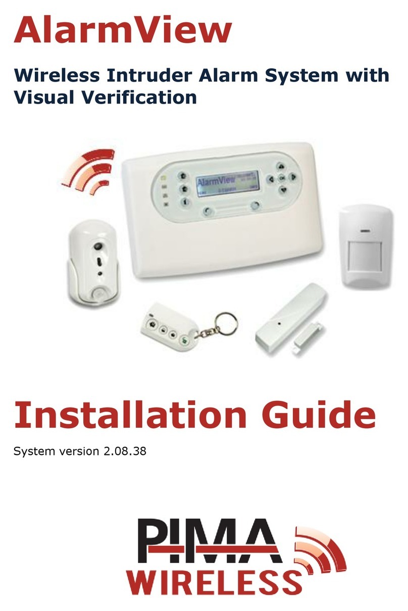
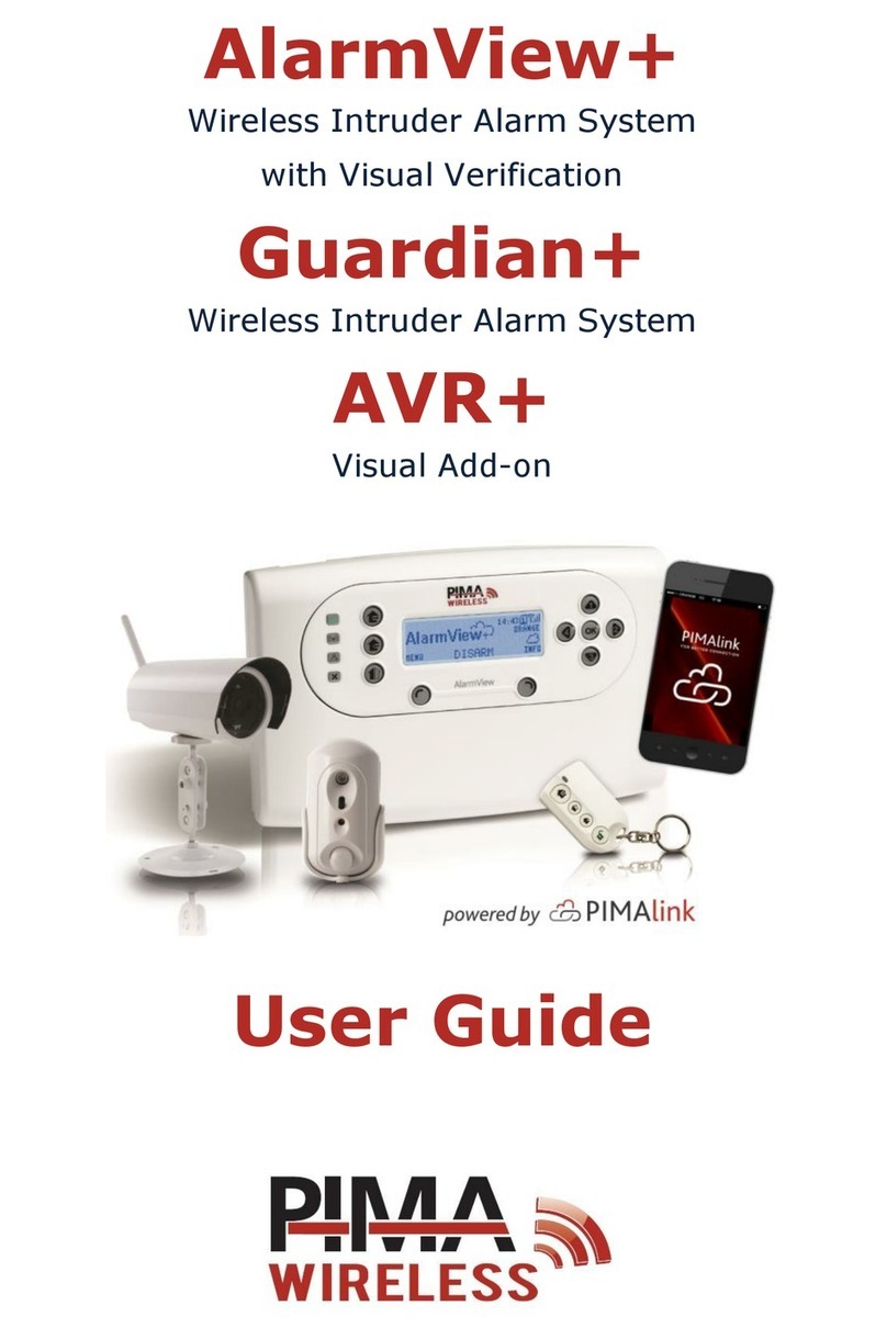
Pima Wireless alarmview+ User manual

AlarmView+
Guardian+
Quick Start Guide
Introduction
This guide will help you to get the AlarmView+ and Guardian+
intruder alarm systems up and running, quickly and efficiently.
We remind you that the alarm systems are supplied with pre-
programmed common settings and pre-enrolled detectors.
To access the Installer menu, press the Menu key (see below) and
enter the installer code (default: 1234). Do the same with the Master
code to enter the user menu (default: 1111).
The Control Panel
The keys
Key
Function
Key
Function
Arm Away
Confirm/Enter
Arm Home
Scroll up/characters: A-Z,
0-9, #+,@-./space_!
Arm Part
Scroll right/duplicate
previous character
Access menus/
Select/Insert
Scroll down/
characters: A-Z, 0-9,
#+,@./space_!
System’s status/
Cancel/Delete
Scroll left/Exit/Back
The LEDs
LED
Color & Status
Description
GREEN, On
Power OK
BLUE, blinking
Wireless communication OK
GREEN, blinking
Off
Cellular reception OK
No cellular reception
ORANGE, 3 blinks
Event in process
RED
System trouble. See the screen for
details (except supervision loss).
LED
Color & Status
Description
WHITE, blinking
ALARM!
Enter the event log to stop the
blinking
The INFO screen
Icon
Description
Icon
Description
1-30
Normally active zone
Blank
Undefined zone
B
Bypassed zone
T
Zone tamper open
X
Supervision loss
GSM network error
Open zone
AC loss
Alarm (now or before)
Low battery
PIMAlink connection OK
Battery disconnected
PIMAlink connection
loss
GSM reception level
Transmission of
message
GPRS transmission
Power-up and mounting
1. Unscrew and remove the
cover of the battery
compartment, connect the
battery wires and close the
cover.
2. Remove the plastic protector
of the connectors’ cavity and
insert the SIM card(s) to the
appropriate slot(s) - SIM 1 in
the upper socket.
3. Plug the AC adapter into its
socket, to the left of the SIM card holder. Do not connect the AC
adapter to power before connecting it to the control panel.
4. Connect the AC adapter to power. Ensure good reception of the
wireless and GSM communications.
5. Mount the control panel where there is optimum wireless reception
from the detectors and peripherals, near mains power supply,
preferably near the main access point of the premises. Make sure
to leave at least 1 m from large metallic objects and Wi-Fi or other
transmitters.
1 2 4 6 7 10
27
17 1812
21 25
T
B X
T
9
B
2924

Only qualified Installer should install this
professional product.
PIR-S/P Motion Detectors
The PIR-S and PIR-P (pet immune) detectors have a detection
range of 12 m, 1100wide, when mounted 2 m above ground.
Place the detectors on a flat surface, away from heat sources,
not above windows and doors. For the PIR-P, install it where
animals can move at least 1 m away from it. Both detectors
are powered by a 3.6 V AA Lithium battery.
To install, release the bottom screw and remove the back cover, remove
the surface knockouts, drill matching holes in the surface (skip this step
with plaster/wood walls) and insert the supplied wall plugs. Fasten the
detector with the supplied screws into the wall plugs, close the cover and
fasten the screw. Use the corner bracket when necessary.
To enroll the detectors, enter the installer code and select
Programming Zones/Peripherals Zones Zone X Device ID
Learn
and push the detector’s (front) button.
Wireless detectors enter a one minute sleep mode after
transmitting a detected movement, to save battery life.
Every further movement during this time will extend
sleep time by one more minute.
SmartView PIR/Camera
The SmartView combines a PIR motion detector with a VGA
CMOS high quality color camera. When mounted at 2.4 m
height the camera’s detection range is 7 m. See the PIR-P
above for placement recommendations.
To install, remove the cradle by releasing its screw, remove
the back cover and insert the supplied battery correctly.
Close the cover. Drill holes for surface or corner mounting (skip this step
with plaster/wood walls), insert wall plugs and fasten the cradle to the
surface with screws. Then mount the detector and fasten its screw, after
adjusting the direction of the detector.
To enroll the detectors, enter the installer code and select
Programming Zones/Peripherals Visual Zones Zone X
Device ID
and type the serial no., which is labeled on the detector.
OutView Outdoor Camera
The OutView is a high quality, still image camera for
outdoor use. It can be triggered by PIR detectors, relays,
etc. (N.C.). The OutView flash covers up to 7 m.
When placing the camera make sure to connect the AC
adapter (12 VDC 2A, AC-DC) close to the camera, indoors
(protected from water), and that the trigger source will
not be more than 50 m away from the camera.
Mount the camera on a solid flat surface. Do not place it
where rain and snow will hit the lens directly. Do not point
the camera towards a light source. Do not have the
camera in a shaded area looking out into a well-lit area.
To mount, drill three holes matching those on the mounting surface,
insert wall plugs and mount the bracket using screws. Connect the
camera’s cable to the terminal block and to power (see the
diagram below).
PIR-O Outdoor Motion Detector
The PIR-O is a dual-lens, pet-immune detector designed for
outdoor installations and powered by two 3.6 V AA Lithium
batteries. It has a detection range of 1 to 11 m, when
mounted at 2.3 m height.
A dip switch on its PCB board is used for setting different
installation locations and functions of the detector. The
complete settings list can be found in the peripherals guide (P/N
4410399).
To mount the PIR-O on a flat surface, disassemble the detector from
the bracket, drill holes matching those on the rotating bracket (see the
diagram below), insert wall plugs (skip this step with plaster/wood
walls) and fasten the bracket with the flat side facing the wall.
Fasten the bracket’s arm to the base cover with the pointy ends facing
away from the detector and hinge on top, and fit the PIR-O onto the
hooks of the rotating bracket. Finally, adjust the detecting angle.
To enroll the detector, see the PIR-S/P section.
DCM Magnetic Door Contact
The DCM is a door contact and a universal transmitter
with a tamper. It sends regular supervision signals. The
DCM is powered by a 3.6 V 1/2 AA Lithium battery.
Mount the magnet on doors’ or windows’ frames, up to
30 mm away from the main unit.
To install the DCM, either release the cover screw,
remove the cover, remove the knockouts and fasten the backplate to
the surface, using the supplied screws, or use the adhesive pads. To
use the universal transmitter see the peripherals guide (P/N 4410399).
To enroll the detector, see the PIR-S/P section.
KF-1/KF-2 Key fobs
One-way and two-way arm/disarm keyfobs. Powered by
CR2032 Lithium battery.
To enroll the keyfobs, enter the installer code and select
Programming Zones/Peripherals Keyfobs/Keypads
Keyfob/Keypad X Device ID
Learn
and press one of the
buttons.
SIR-B/R/O External Siren
The wireless siren/strobe produces a minimum of
104 dBA sound pressure, at 1 m. It is powered by
four Alkaline D batteries and is IP43 water & UV
proof.
To install, remove the cover, slide the power switch
to the ON position, remove the four battery compartment’s cover
screws and insert the batteries. Replace the cover and fasten the
screws gently.
To enroll the siren: enter the installer code and select
Programming
Zones/Peripherals External Siren Device ID
. Enter the labeled
serial number and press OK. To test the siren select
Service Tests
External Siren test Test
Mount the siren on a flat surface, using the supplied wall plugs and
screws and close the cover.
Trigger source (N.C.)
OutView
AC-DC Adapter
Junction box
Red
Black
Yellow
AC-DC Adapter
Trigger
source
(+)
(-)
OutView
Up to 50 m long

RWK Remote Keypad
The RWK is a two-way wireless keypad for arming & disarming. It is
powered by one CR2450 Lithium battery, and is IP41 water resistance.
To mount the keypad on a flat surface, open the unit and insert the
supplied battery. Remove the two covers (top and bottom) using a
screwdriver and drill holes for mounting the keyboard (skip this step
with plaster/wood walls).
To enroll the keypad, enter the installer code and select
Programming
Zones/Peripherals Keyfobs/Keypads Keyfob/Keypad X
Device ID.
Press any button of the keypad and when detected by the
control panel, press OK.
How to pair to the PIMAlink App
To pair the control panel with PIMAlink:
1. Access the user menu and select
Service
PIMAlink
.
2. Press
Pair
and wait for the pairing code to show up.
3. Use the code to pair any device (up to 32, up to 6 user
codes not including the Master code) with the PIMAlink
app, to the control panel. The code expires after 10
min. Repeat the steps to produce another code, if you
need it in the future.
Other products by Pima
PCP
Panic Pendant and Wrist Watch
SIR-I
Indoor Siren
SM
Smoke Detector
TD-5
Temperature Detector
DCO
Carbon Monoxide Detector
WLD
Water Leakage Detector
REP
Wireless Repeater
P/N: 4410376
*4410376*
Revision C2, XX en (Jul 2016)
Copyright 2016 PIMA Electronic Systems Ltd.
All rights reserved. E&OE
PIMA Electronic Systems Ltd. WWW.PIMA-ALARMS.COM
5 Hatzoref Street, Holon 5885633, ISRAEL
Tel: +972.3.6506414 Fax: +972.3.5500442
Email: support@pima-alarms.com

The Menu Map
ACCESS CODE
ACCESS MODE
TRIGGER UPON
OUTPUT TYPE
PULSE
SIM MODE
SIM 1 (MAIN)
SIM 2 (BACKUP)
PASSWORD
ACCESS CODE
SYSTEM NAME
CONTACT 1-6
EVENT REPORT
DEVICE ID
START DELAY
CUT OFF
OPTIONS (AWAY)
STATE
ZONES
VISUAL ZONES
ZONE 1-23
ZONE 24 (WIRED)
ZONE 25-30 (VISUAL)
KEYFOBS/KEYPADS KEYFOB/KEYPAD 1-6
PANIC BUTTONS PANIC BUTTON 1-6
BUILT-IN SIREN CUT OFF
STATE
RETURN TO DEFAULTS
CLEAR PASSWORDS
CLEAR ZONES
INIT ALL
CONTACTS
CMS CONTACTS
COMMUNICATION
FACTORY DEFAULTS
LOCAL PROGRAMMING
FIRMWARE UPGRADE
MOBILE
IP
PORT
CMS PROTOCOL
PERIODIC TEST
GPRS ALWAYS ON*
BACKUP**
ACCT. ID
CMS 1-2
EVENT REPORT
RETRY OPTIONS
ENTRY/EXIT ENTRY DELAY
EXIT DELAY
TONE
SYSTEM OPTIONS
ARM/DISARM
PGM OUTPUT
TRIGGER INPUTS
SIREN FOLLOWER
ENTRY/EXIT
NOT READY/ALARM
NOT USED
AWAY ARM
HOME ARM
PART ARM
POWER FAULT
MEDICAL
BURGLARY
FIRE
REMOTE SMS
TRIGGER 1-3
ALWAYS
USER INITIATED
SINGLE SIM (MAIN)
DUAL SIM
SELECT OPERATOR
MOBILE PHONE
EMAIL (BY MMS)
CONTACT NAME
OPTIONS
PROGRAMMING
BACK
EVENT LOG
BACK
OPTIONS
BACK
SERVICE
BACK
PASSWORDS
BACK
SET CLOCK
BACK
*Trigger 1 only
x GLOBAL CHIME
x REMOTE LOOK-IN
x VISUAL EVENTS
GLOBAL SETTINGS
ZONE BYPASS
CONTACTS
PIMAlink BACKUP
DISABLE NOTIF.
ENABLE NOTIF.
CONTACT 1-6
PIMAlink
ENABLE PROGRAMMING
TESTS
DISPLAY VERSION
SYSTEM RESET
PAIR
UN-PAIR
ZONE
EXTERNAL SIREN
BUILT-IN SIREN
COMMUNICATION
SYSTEM SELF TEST
REGULAR USERS*
MASTER USER*
DURESS CODE*
24H LIMITED CODE*
INSTALLER**
*Master user only
** Installer only
TIME
DATE
ZONES/PERIPHERALS
EXT. SIREN
DEVICE ID
NAME
STATE
DEVICE ID
TYPE
NAME
STATE
1ARMING TONES
1ENTRY/EXIT TONES
USER INITIATED
DISABLE
ALWAYS
DURING DISARM
NOT USED
AWAY ARM
HOME ARM
PART ARM
WIRED/EXT ZONE*
STEADY NO
STEADY NC
PULSE LOW TO HIGH
PULSE HIGH TO LOW
DISABLE
SIA SMS
CID SMS
GPES-CID
GPRS-VISUAL/CID
x FORCE ARM
x ONE-KEY ARMING
x WL KEYPAD ONLY
1BACKUP BAT. LOSS
1AC LOSS
1ZONE SUPERVS.LOSS
1SIM FAULTS
DEVICE ID
ZONE TYPE
ARM SET
NAME
SWINGER SHUTDOWN
OPTIONS
STATE
OPTIONS
OVERRIDING
STOP COMM.
BACK
NORMAL
ENTRY/EXIT
FOLLOWER
24H
PANIC
MEDICAL
FIRE
x HOME
x AWAY
q PART
DISABLED
1 ALARM
2 ALARMS
3 ALARMS
Zones 1-24
x SIREN
xCHIME
xFORCE ARM
Zones 25-30
xSIREN
xFORCE ARM
xVIDEO VERIF.
xREMOTE LOOK-IN
qLED INDICATION
TSMS REMOTE CMD.
TREMOTE LOOK-IN
TSMS EVENT REPORT
TMMS VISUAL
1EMAIL EVENT
1EMAIL VISUAL
TALARM EVANTS
TDIS/ARM REPORT
TPOWER REPORT
TSERVICE REPORT
TBURGLARY REPORT
TBURGLARY RESTORE
TFIRE REPORT
TFIRE RESTORE
TARM/DISARM REPORT
TSERVICE REPORT
TSERVICE RESTORE
TPOWER REPORT
TPOWER RESTORE
TMEDICAL REPORT
TMEDICAL RESTORE
TVISUAL REPORT
INTERVAL TIMEOUT
DELAY TIMEOUT
** CMS 2 only
BACKUP
DUPLICATE
* CMS 1 only
DISABLE
PING 30 SEC
PING 45 SEC
PING 60 SEC
PING 90 SEC
DISABLE
5 MIN
10 MIN
30 MIN
60 MIN
24 HOURS
1 WEEK
1 MONTH
HIGH
LOW
REMOTE ACCESS
MEDICAL
PANIC
Other manuals for alarmview+
1
This manual suits for next models
1
Table of contents
Other Pima Wireless Security System manuals