EPIC SAFETY Surf-km User manual

surf-km & surf-k
LTE Alarm System Communicators
Installation Guide

Contents
1. Overview ............................................................................................................................................... 3
1.1. Description.................................................................................................................................... 3
1.2. In the box ...................................................................................................................................... 4
1.3. Identifying the Parts...................................................................................................................... 4
2. Introduction .......................................................................................................................................... 5
2.1. Features ........................................................................................................................................ 5
2.2. Surf codes...................................................................................................................................... 5
2.3. Monitoring options ....................................................................................................................... 5
3. Pre-Installation Recommendations ...................................................................................................... 6
3.1. Antenna Installation...................................................................................................................... 6
3.2. Cable length .................................................................................................................................. 6
4. Performance Guide ............................................................................................................................... 6
4.1. Signal level .................................................................................................................................... 6
4.2. Temperature ................................................................................................................................. 7
4.3. Voltage .......................................................................................................................................... 7
4.4. Button Functions........................................................................................................................... 7
4.5. LED indications.............................................................................................................................. 8
4.6. Terminal Connections ................................................................................................................... 9
Other Hardware: .................................................................................................................................10
•RF expansion port is for future addition of more wireless capabilities to Surf-K and Surf-KM..10
•Antenna connector is for connecting our full frequency LTE antenna. ......................................10
4.7. Connections description ............................................................................................................. 10
4.7.1. Power .................................................................................................................................. 10
4.7.2. Keybus.................................................................................................................................10
4.7.3. Tip/Ring ...............................................................................................................................11
4.7.4. Zones...................................................................................................................................11
4.7.5. PGMs ................................................................................................................................... 11
5. Installation & Programming................................................................................................................ 11
5.1. DSC Power Series Panels............................................................................................................. 11
5.2. Programming recommendations ............................................................................................ 12
5.2.1. 1616/1832/1864 ................................................................................................................. 12
5.2.2. PC 5020 ...............................................................................................................................13

5.2.3. PC 5010 ...............................................................................................................................14
5.2 Interlogix Panels (GE) .................................................................................................................. 16
5.2.1 GE Concord.......................................................................................................................... 16
5.3 Paradox Panels............................................................................................................................16
5.3.1 Espirit 728, 728 Express, 738, 738 Express ......................................................................... 16
5.3.2 Paradox SP6000, SP 5500, SP7000, SP 4000 ....................................................................... 18
5.4 Generic Panels ............................................................................................................................ 18
6. Trouble Conditions..............................................................................................................................19
6.1 Primary Power Failure................................................................................................................. 19
6.2 Network Signal............................................................................................................................ 19
6.3 No Cellular Service ......................................................................................................................20
6.4 Tip & Ring Communication Status .............................................................................................. 20
6.5 SIM Card Error............................................................................................................................. 20
6.6 Keybus Communication Failure .................................................................................................. 20
6.7 Aryo Communication Failure ......................................................................................................20
6.8 High/Low Temperature............................................................................................................... 20
7. Troubleshooting.................................................................................................................................. 21
8. Specifications ......................................................................................................................................22
9. Repair under warranty........................................................................................................................ 23
10. Terms and conditions...................................................................................................................... 24
11. Product Warranty ...........................................................................................................................25
12. Limitation of Warranty.................................................................................................................... 26
1.Overview
1.1. Description
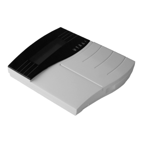
Surf-km and Surf-k are primary alarm communicators that use cellular (LTE) technology.
They use line capture to monitor any alarm system that uses SIA and CID format. They can
also connect to the DSC power series keybus to monitor these systems and provide users
the ability to access their systems remotely from anywhere via our Aryo Cloud platform
and iOS and Android smartphones. Surf-km and Surf-k use 3 zones to monitor legacy
systems for generic burglary, fire, and panic alarms. Surf-km and Surf-k use zone 1 and

PGM 1 fort keyswitch arming and disarming. PGM 2 is used to trigger a supervisory zone on
the panel for Surf-km and Surf-k troubles.
1.2. In the box
•Surf-k or Surf-km
•Quick installation guide
•Antenna (75cm)
1.3. Identifying the Parts
1) Antenna connector
2) SIM card
3) Mounting holes
4) Terminal block
5) Wire entrance
6) RF Expansion port
7) LED indicators

2. Introduction
2.1. Features
•The use of LTE, NB-IoT by Surf-K and LTE, CAT-M1 by Surf-KM, makes them
capable of covering a wide area using low power cellular technology.
•Line capture allows Surf-K and Surf-KM to detect and capture CID and SIA events
and monitor any alarm system that uses these formats.
•Keybus allows Surf-K and Surf-KM to communicate with the Keypad in a faster
way. Also giving the possibility of having troubles showing on the Dashboard in
case of any unforeseen event.
•In case the panel doesn’t support Keybus, Surf-K and Surf-KM can use 3 input
zones to monitor generic alarm outputs of the panels by providing generic
Burglary, Fire, and Panic inputs to monitor these systems.
•In case a panel doesn’t support Keybus, Surf-K and Surf-KM could also use
Tip/Ring – Key Switch Arming to arm and disarm your system.
•Surf-K and Surf-KM display Full Event Reporting when connected to Aryo Cloud.
•Zone & Partition Status are shown on the platform, assigned by the Dealer.
•OTA Firmware Updates are provided in real time, keeping your system up to date.
•Connected to Aryo Cloud, Surf-K & Surf-KM will provide Automatic Status
Detection, disclosing in real time the status of the connection, network, voltage,
etc.
2.2. Surf codes
Surf-K and Surf-KM uses one master code (for main user) and 40 user codes to arm and
disarm the host control panel when keyswitch arming is used or If Keybus connection is not
used or available. These Codes are different from the host control panel Master and User
Codes. If SURF-K or Surf-KM master code is lost, it can be reprogrammed by the Dealer.
2.3. Monitoring options
2.3.1. Tip/Ring monitoring– Is used to connect to panel TIP and RING terminals for
detection and capture of CID and SIA format events. These signals are sent to Aryo
cloud and the monitoring center.
2.3.2. Keybus monitoring – is used to connect to DSC power series keybus Yellow and
Green terminals to fully interact with panel keybus communication. The events and
status signals are sent to Aryo cloud and the monitoring center.
2.3.3. Keybus and Tip/Ring monitoring - Are used to connect to panel TIP and RING
terminals for detection and capture of CID and SIA format events and to connect to
DSC power series keybus Yellow and Green terminals to fully interact with panel

keybus communication. The events and status signals are sent to Aryo cloud and the
monitoring center.
2.3.4. Generic panel monitoring - Surf-km and Surf-k use 3 input zones to monitor alarm
outputs of the panels for Burglary, Fire, and Panic when CID and SIA formats are not
used.
3. Pre-Installation Recommendations
•Explore a placement test to find a suitable location with best LTE signal.
•Wiring can only be done when both Surf and the alarm panel are powered down.
•Do not route any wire over the alarm panel or Surf circuit boards.
•Install and program your alarm panel before connecting it to Surf-K/ Surf-KM.
•Install and operate Surf within its specified temperature ranges to prevent any possible
damages.
Do NOT install the unit close to heating source, direct sunlight or in a damp location.
•Do NOT connect Surf-k and Surf-km to a phone line. This will damage Surf.
•Always connect Surf to approved power source and battery backup.
•To remotely Arm Away a panel that has a configurable Auto Stay option, this feature
should be disabled.
3.1. Antenna Installation
•Surf-K and Surf-KM use full-band LTE magnetic antenna. The antenna can be connected
to Surf-K and Surf-KM antenna connector as shown in section 1.3.
•Antenna should be placed high in an open area within the building and far from any
interference, metals, pipes, and concrete.
•DO NOT install the antenna in a metal enclosure.
3.2. Cable length
For suitable location to install Surf-K and Surf-KM, they can be installed up to 1000 feet
away from the control panel. The distance would increase if you use higher guage wire.
4. Performance Guide
4.1. Signal level
The signal level is reported using RSSI (received signal strength indicator) method which
can be converted to dBm (decibel-milliwatts). The RSSI and corresponding signal strength
bar can be seen in the table below:
RSSI
Signal level (dBm)
Service Level
0 - 2
-113 ~ -109
No service
3 - 9
-108 ~ -95
Poor – will trigger signal strength trouble event

10 -14
-93 ~ -85
Acceptable
15 - 19
-83 ~ -75
Good
20 - 31
-73 ~ -51
Excellent
4.2. Temperature
For correct operation, the unit must be in the operating range for temperature level. The
different temperature levels and their corresponding interpretations are listed below. The
temperature for the unit can be viewed on the cloud.
SURF-K/KM (°C)
Interpretation
< -5 °C
Low – Surf will trigger low temperature trouble event.
-5 °C to 50 °C
Normal
> 51 °C
High – Surf will trigger high temperature trouble event.
4.3. Voltage
For proper operation, both alarm panel and SURF-K/KM should be powered by approved
power source within the recommended range. Different voltage levels and corresponding
interpretations for the alarm panel are listed below.
Panel Voltage (VDC)
Interpretation
< 9
Low voltage - Surf will trigger low voltage trouble event.
10.1 – 13
Acceptable
13.1 – 14.5
Good
> 14.5
High voltage - Surf will trigger high voltage trouble event.
4.4. Button Functions
Surf button is used for a few functions according to the table below:
Button press
Time(sec)
Function
Name Function Use Duration time
LED indicators
5 sec< Self-Test
To send device info (HW & FW
versions, signal level, power,
temperature) to our cloud
Immediate
Blink once
5 sec
Signal
level
Mode
To select the best location for
mounting Surf by obtaining signal
level of Surf for each location:
Led 1 Blink 0 ~ 9
20 sec
Slow blink

4.5. LED indications
Condition
Status
LED Color On Off
Fast
Blink
1
Flash
2
Flash
3 Flash
Power
DC power on
1
Red
X
DC power off
1
Red
X
Device not Registered
with cloud 1 Red X
SURF-K/KM Trouble
(POWER, Signal,
Temperature, Keybus,
Communication)
1 Red X
Cellular
Network
Surf can not find the
cellular network
2 Green X
Poor Signal
2
Green
X
Acceptable Signal
2
Green
X
Good Signal
2
Green
X
Strong Signal
2
Green
X
Server
Network
Connecting to server
3
Green
X
Disconnected from
server 3 Green X
Communicating with
server
3 Green X
Connected to server,
but not
communicating
3 Green X
Led 1 On 10 ~ 12
Led 2 Blink 13 ~ 16
Led 2 On 17 ~ 19
Led 3 Blink 20 ~ 22
Led 3 On 23 ~ 25
Led 4 Blink 26 ~ 28
Led 4 On 29 ~ 31
10 sec
Reboot
Device
If required based on
troubleshooting guide Immediately
Fast blinking
15 sec
Reset
SSL
When Surf is reused for a new
client or moved to a new location. Immediately
Alter blinking

Panel
Communi
cation
Connected to the
Tip/Ring 4 Green X
Connected to the
Keybus
X
Connected to Tip/Ring
and Keybus 4 Green X
Generic panel type
X
FW
Update
Firmware update in
progress 4 Green
Alternate
blinking
4.6. Terminal Connections
SURF-K / Surf-KM terminals description
Terminal Name
Connections
Tip (T)
Connection to panel phone TIP terminal for detection
and capture of CID and SIA events to be sent to Aryo
cloud and the monitoring center
Ring ®
Connection to panel phone RING terminal for
detection and capture of CID and SIA events to be sent
to Aryo cloud and the monitoring center
Keybus Yellow (Y)
To be connected to DSC power series keybus Yellow
terminal to fully interact with keybus communication
Keybus Green (G)
To be connected to DSC power series keybus Green
terminal to fully interact with keybus communication

PGM 1 (P1)
To trigger a keyswitch zone of the panel for arming /
disarming
PGM 2 (P2)
Connects a supervisory zone on the host panel to
trigger trouble events when SURF-K / Surf-KM trouble
occurs. For Surf-K/KM troubles, please see Section 6.
Zone 1 (Z1)
(Dry Contact only)
To provide arm/disarm status of the panel when
connected to arm status PGM of the host panel
Zone 2 (Z2)
(Dry Contact only)
Common Burglary Input used to monitor burglary
alarm signal received from the output of any control
panel. (For DSC panels, this zone can be used for both fire and
burglary detection when connected to the siren output)
Zone 3 (Z3)
(Dry Contact only)
Common Fire Input used to monitor fire alarm signal
received from the output of any control panel
Zone 4 (Z4)
(Dry Contact only)
Common Panic Input used to monitor panic alarm
signal received from the output of any control panel
Ground (GND)
Ground
Power (PWR)
12-14 VDC
Other Hardware:
•RF expansion port is for future addition of more wireless capabilities to Surf-K
and Surf-KM.
•Antenna connector is for connecting our full frequency LTE antenna.
4.7. Connections description
4.7.1. Power
SURF-K / Surf-KM could be powered by host control panel auxiliary 12-14 VDC power.
External auxiliary power source with back up battery can be used if they use common
ground. These devices can still operate with power range of 5 to 20 VDC. SURF-K / Surf-
KM always monitor panel voltage and will generate power trouble when voltage drops
below 9VDC.
4.7.2. Keybus
SURF-K/KM supports DSC power series Keybus interface. Yellow (Y) and Green (G)
terminals can be connected to Surf to allow interaction with DSC power series panels to
monitor events and provide status of the host alarm panel.

They can also provide users the ability to access their systems remotely from anywhere
via our Aryo Cloud platform and iOS and Android Apps
4.7.3. Tip/Ring
SURF-K/KM connect to Tip/Ring interface of any alarm panel that uses CID or SIA
formats to capture all generated signals and send them to our Aryo cloud and then
monitoring centers.
4.7.4. Zones
SURF-K / Surf-KM provide 4 zone inputs. Zone 1 is used for arm status in keyswitch
arming and 3 zones are used to monitor generic alarm panels that do not use CID/SIA
formats. Zones 2, 3 and 4 zones would be used for generic burglary, fire, and panic
alarms as per section 1.4`s table.
4.7.5. PGMs
SURF-K/KM has two PGM outputs are for keyswitch arming and Surf troubles as per
section 1.4`s table.
5. Installation & Programming
5.1. DSC Power Series Panels
5.1.1. Wiring Diagram

5.2. Programming recommendations
5.2.1. 1616/1832/1864
Section
Description
015
Turn options 4 on and options 7 and 8 off
301
Enter any phone number
310
Enter a system account number
311-318
If system has multiple partitions, enter an account number for each
partition if any format other than SIA is used. 311 for partition 1, 312 for
partition 2, and so on.
350
Enter 03 for CID or 04 for SIA reporting
351-358
Turn option 1 on for each partition alarm/restore reporting. 351 is for

partition 1, 352 is for partition 2, and so on.
367-374
Turn option 1 on for each partition open/close reporting. 367 is for partition
1, 368 is for partition 2, and so on.
380
Turn option 1 on to enable communicator for digital monitoring.
Options 3 and 4 must be off for DTMF dialing.
Note: If Keybus monitoring reporting is selected, option 1 must be off.
381
Options 3 and 7 must be off for automatic SIA and CID reporting
To enable keyswitch arming/disarming and make it work properly, program the following
sections:
Section
Entry/Description
001
Program a zone as type 22 for momentary keyswitch arm
009
Program a PGM as 05 for system arm status
021
Turn on option 6 for Keyswitch arming/disarming at any time
023
Turn on option 8 for Keyswitch to arm in Away mode
5.2.2. PC 5020
Sections
Programing Description
015
Turn options 4 on and options 7 and 8 off
301
Enter a phone number
310
Enter a system account number
311-317
If system has multiple partitions, enter an account number for each
partition if any format other than SIA is used. 311 for partition 1, 312 for
partition 2, and so on.
350
Enter 03 for CID or 04 for SIA reporting
351-358
Turn option 1 on for each partition alarm/restore reporting. 351 is for
partition 1, 352 is for partition 2, and so on.
367-374
Turn option 1 on for each partition open/close reporting. 367 is for
partition 1, 368 is for partition 2, and so on.
380
Turn option 1 on to enable communicator for digital monitoring. Options
3 and 4 must be off for DTMF dialing.
Note: If Keybus monitoring reporting is selected, option 1 must be off.

381
Options 3 and 7 must be off for automatic SIA and CID reporting
To enable keyswitch arming/disarming and make it work properly, program the following
sections:
Section
Entry/Description
001
Program a zone as type 22 for momentary keyswitch arm
009
Program a PGM as 05 for system arm status
5.2.3. PC 5010
Sections
Programing Description
015
Turn options 4 on and options 7 and 8 off
301
Enter any phone number
310
Enter an account number for each partition
360
Enter 03 for CID or 04 for SIA reporting
361-362
Turn option 1 on for each partition alarm/restore reporting. 361 is for
partition 1, 362 is for partition 2.
365-366
Turn option 1 on for each partition open/close reporting. 365 is for
partition 1, 366 is for partition 2.
380
Turn option 1 on to enable communicator for digital monitoring option.
Options 3 and 4 must be off.
Note: If Keybus monitoring reporting is selected, option 1 must be off.
381
Options 3 must be off for automatic SIA reporting. All CID codes from
section 320 to 353 must be manually entered when CID reporting is
used.
To enable keyswitch arming/disarming, program the following sections:
Section
Entry/Description
001
Program a zone as type 22 for momentary keyswitch arm
009
Program a PGM as 05 for system arm status
5.2.4. PC580, PC585, PC 1555
Sections
Programing Description

015
Turn options 4 on and options 7 and 8 off
301
Enter any phone number
310
Enter account number
360
Enter 03 for CID reporting or 04 for SIA reporting
361
Turn option 1 on for alarm/restore reporting.
365
Turn option 1 on for open/close reporting.
380
Turn option 1 on to enable communicator for digital monitoring.
Options
3 and 4 must be off.
Note: If Keybus monitoring reporting is selected, option 1 must be off.
381
Options 3 and 7 must be off for automatic SIA and CID reporting
To enable keyswitch arming/disarming, program the following sections:
Section
Entry/Description
001
Program a zone as type 22 for momentary keyswitch arm
09
Program a PGM as 05 for system arm status

5.2 Interlogix Panels (GE)
5.2.1 GE Concord
5.2.1.1 Wiring Diagram
5.3 Paradox Panels
5.3.1 Espirit 728, 728 Express, 738, 738 Express
5.3.1.1 Wiring Diagram


5.3.2 Paradox SP6000, SP 5500, SP7000, SP 4000
5.3.2.1 Wiring Diagram
5.4 Generic Panels
5.4.1 Wiring Diagram

6. Trouble Conditions
6.1 Primary Power Failure
If panel power fails below 9V, SURF-K/KM will trigger a trouble event on the host panel and send the
signal to our cloud server and CMS.
6.2 Network Signal
If radio signal falls below 9, Surf-K/Surf-KM will trigger a trouble event on the host panel
and send the signal to our cloud server and CMS.

6.3 No Cellular Service
If Surf-K/Surf-KM cannot contact to the cellular tower (RSSI is 0 or 99), Surf-K/Surf-KM will
trigger a trouble event on the host panel and send the signal to our cloud server and CMS.
6.4 Tip & Ring Communication Status
During normal operation, if Tip & Ring signal is not detected, Surf-K/Surf-KM will trigger a
trouble event on the host panel and send the signal to our cloud server and CMS.
6.5 SIM Card Error
If there is a SIM Card Error, Surf-K/Surf-KM will trigger a trouble event on the host panel and
send the signal to our cloud server and CMS.
6.6 Keybus Communication Failure
When connected to a DSC alarm panel keybus, Surf-K/Surf-KM continuously supervises the
keybus communication path for normal operation. If Surf-K/Surf-KM stops receiving data
from the keybus line, Surf-K/Surf-KM will trigger a trouble event on the host panel and send
the signal to our cloud server and CMS.
6.7 Aryo Communication Failure
If there is any error or failure in our communication with our cloud, Surf-K/Surf-KM will
trigger a trouble event on the host panel and send the signal to our cloud server and CMS.
6.8 High/Low Temperature
If temperature goes above 50 degrees Celsius or falls below -5 degree Celsius, Surf-K/Surf-
KM will trigger a trouble event on the host panel and send the signal to our cloud server and
CMS.
Surf-K/KM also monitors some important parameters such as panel power, temperature,
communication of Keybus and Tip/Ring of the host panel for proper functionality and would
report these conditions to Aryo Cloud and the central station.
CID and SIA codes for troubles
Peripheral Tamper 341
Peripheral Trouble (Supervisory) 330
Peripheral Low Battery 338
Peripheral AC Fail 342
Comm Test Fail 358
Expansion Module Failure 333 (0-ethernet, 1-wifi, 2-wifi soft AP, 3-cellular)
This manual suits for next models
1
Table of contents
Other EPIC SAFETY Security System manuals
Popular Security System manuals by other brands

MOVING INTELLIGENCE
MOVING INTELLIGENCE PHANTOM Vanguard Caravan Alarm manual

ESP
ESP FHDV 4 R user manual
Masterlock
Masterlock 8254DAT installation instructions
Entrematic
Entrematic Ditec VALFC installation manual
Paradox
Paradox ESPRIT 728 ULT Reference & installation manual
Abus
Abus CITADEL Alarm Set Micral Fitting and operating instructions
