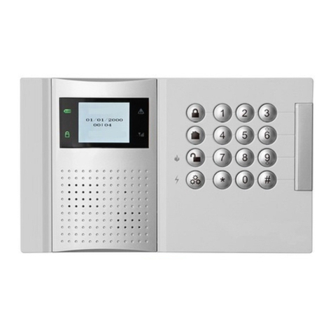
LONGHORN LHD6000 User manual

INSTALLATION
MANUAL
LHD6000
Manufacturer: Shenzhen Longhorn Technology Co., Ltd.
Add: Longhorn Hi-Tech Estate, TongFuyu Industrial Avenue,
Longhua, Shenzhen G. D. China
Post number: 518109
Tel: 800 830 8196
Fax: +86-755-28140429
E-mail: service@long-horn.com
Web address: http://www.long-horn.com

INSTALLATION MANUAL

Thank you for using LHD6000 alarm system of Longhorn. Please read the Installation
Manual carefully before installing and using the alarm system in order to acquaint you with
its remarkable performance and use this system better.
If you have any problem while using, please contact the installer or our Customer Service
Center: 800 830 8196.
INSTALLATION INFORMATION
User name
User address
Installer name
Installation company
Installation date
Tel of installation company
Fax of installation company
Alarm monitoring center
Address of alarm monitoring center
Tel of alarm monitoring center
Tel of the control panel
Note: This blank should be filled by installation principals and confirmed by relevant companies or principals.
CONTAINER LOADING LIST
The components of the product are packed in a box as followed. Open the box and check it carefully. If finding
deficiency, please fetch the provider in time.
Note: There are two anti-tamper switches of control panel, twenty-four EOL resistances (2.2k ), two keys for cabinet of
control panel, telephone line, telescopic antenna, keypad anti-tamper switch spring, screw, expansion pipe;and
keypad fixed iron stand, connecting line, installation frame, keypad wring plate in secret installation. More
keypads and remote controllers can be purchased in addition.
1
2
3
4
5
Master controller
Wireless remote controller
Installation manual
Keypad
Accessory bag
1
2
1
1
1
Number Name Amount
23
1
2
3
4
5
6
7
8
9
10
11
12
13
14
15
16
Bypass or notInstallation position Type Zone number
Wire zones of the control panel
16.Table of zone types descriptions
Wireless zones
21
22
23
24
25
26
27
28
Keypad wire zones
41
42
43
44
45
46
47
48

22
95
150 30
264
274
86
Control panel:
15. Technical parameters
Size: 274mm×264mm×86mm
Operating voltage: 220V AC
Static operating current: 120mA
Operating temperature: -10℃~+55℃
Keypad:
Size: 150mm×95mm×30mm
Operating voltage: 12V DC
Static operating current: 100mA
Operating temperature: -10℃~+55℃
Wireless remote controller:
Operating frequency: 315MHz/433MHz/868MHz (optional)
Effective distance: ≥50 m (without obstacles)
Battery: two button batteries (2016), 75mAh
Potential reasons SolutionsTypes of fault
Code learn unsuccessful
Different detectors use the same
code learn
The different carrier frequency of the
detector and the control panel
The detector does not work normally
Cancel this zone ,check the code
learn again, make sure the detector
code learn has not been used
Change the detector and try again
Confirm carrier frequency of the
detector
Cancel this wireless zone change
the code learn and try again
Wireless zone misinformation Different wireless zones use the same
code learn
Figure 2: Appearance and dimension of
the keypad
Figure 1: Appearance and dimension of
the master controller

CONTENTS
System installation figure........................................................................................... ........... 1
1. General............................................................................................................................. 2
2. Main functions &features.................................................................................................... 2
3. Terms definitions................................................................................................................ 2
4. Notice before using............................................................................................................ 3
5. System installation............................................................................................................. 3
5.1 General requirements of engineering installation.......................................................... 3
5.2 Control panel installation....................................................................................... 3
5.3 AC connection............................................................................................................. 3
5.4 Standby power connection........................................................................................... 3
5.5 Keypad installation...................................................................................................... 4
5.6 Bell output terminal...................................................................................................... 6
5.7 Anti-tamper switch installation...................................................................................... 6
5.8 Auxiliary power output terminal.................................................................................... 6
5.9 Loop input................................................................................................................... 6
5.10 Telephone line connection.......................................................................................... 6
5.11 Telescopic antenna installation................................................................................... 7
5.12 AC power connection................................................................................................. 7
6. Keypad panel composition................................................................................................. 7
7. Alarm mode....................................................................................................................... 8
8. Zone type and zone number............................................................................................... 8
8.1 Zone type..................................................................................................................... 8
8.2 zone number............................................................................................................... 9
9. Keypad operation.............................................................................................................. 9
9.1 Password input............................................................................................................ 9
9.2 Function key operation................................................................................................. 9
9.3 Parameters setting.................................................................................................... 10
10. Wireless remote controller operation.............................................................................. 19
10.1 Arm-away.............................................................................................................. 19
10.2 Arm-stay................................................................................................................ 19
10.3 Disarm.................................................................................................................. 19
10.4 Panic..................................................................................................................... 19
11. Remote phone operation................................................................................................ 20
11.1 Telephone disarm .................................................................................................. 20
11.2 Telephone arm-away............................................................................................... 20
11.3 Telephone arm-stay................................................................................................. 20
3. Alarm warning devices such as bells may not alert people if they are installed in an improper position. If the
alarm bell is installed outside, there are less likely to waken or alert people inside the bedrooms.
4. Telephone line used to transmit alarm signals may be out of service for any reason, or can not perform
communication normally for vicious attack.
5. Unsuitable installation position of detectors. If smoke detector is installed in an improper position, it is not easy
for smoke to enter the detecting area. Because of doors or walls, it is hard for the detector to sense fires in other
rooms, e.g. the detector in the first floor can not sense fires in the second floor.
6. Lack of maintenance may lead to the system disabled. Weekly testing is required to ensure proper operation of
the system.
14. Troubleshooting
The controller plug is not inserted in
DC socket, or it is not connected well Check the connection of the plug
or replace the socket.
Check whether keypad is wired
incorrectly or not, and wire
Keypad is wired incorrectly
Telephone can not work normally
as the system is connected into
telephone network
Few ringing attempts lead the
system to hang up the phone
automatically
Wireless remote controller is too far
from the controller or blocked by
obstacles.
Increase ringing attempts. Refer
to ringing attempts adjustment
Replace it with a new battery
Keypad logout
Battery is drained
Enroll the detector again.
Do not enroll wireless detector or
the detector is removed
Remove the keypad from the
control panel, then connect it to
the control panel again or restart
the system
Do not set correct phone number
User's phone is busy during alarm Set two more phone numbers
Set correct phone number
The system does not dial to alarm
when alarm happens
Potential reasons Solutions
The zone is bypassed Cancel bypass of the zone
When disarm, zone 1,2,3 do not
alarm; when arm-stay, zone 2 do
not alarm. Operate normally
Types of fault
Remote controller can not operate
the system
Keypad can not operate the system
Wireless zones can not monitor
normally
The indicator of power on keypad
does not work
The system has no feedback when
zone is touched
Adjust the distance or angle
be tw een th e sy st em and
wireless remote controller
Enroll wireless remote controller
without programming Enroll wireless remote controller
with programming
When emergencies happen or the
system enters delay status, it will
not arm
Reset the time for arm/disarmTime for arm/disarm may be the same
Refer to Timed arm/disarm
Timed arm/disarm can not work
Timed arm/disarm is not set in valid
status Set timed arm/disarm in valid status

Communication between control panel and alarm center have two formats ADEMCO 4+1 and ADEMCO Contact
ID.The event code identifications as followed:
12. Answering alarm communication code
21
11.4 Phone field monitor........................................................................................................... 20
11.5 Hearing current alarm type................................................................................................ 20
11.6 Hang-up/stop alarm dialing............................................................................................... 20
12. Answering alarm communication code..................................................................................... 21
13. Limitations of the alarm system................................................................................................. 21
14. Troubleshooting....................................................................................................................... 21
15. Technical parameters............................................................................................................... 22
16. Diagrams of zone type setting................................................................................................... 23
00
01
02
11~15
21~25
98
99
NO.
100
110
121
131
132
134
151
301
302
401
441
521
145
382
570
455
ADEMCO Contact ID TABLE OF EVENT CODES
DEFINITION
Panic zone alarm
Fire zone alarm
Perimeter zone alarm
Active zone alarm
Entry/Exit zone alarm
Duress code, Duress zone alarm
Gas zone alarm
AC power failure
DC power low-voltage
Keypad loss
Arm/Disarm operation
Arm-stay operation
Auto-arm/disarm failing
Bell canceling function
Keypad Anti-tamper
Control panel anti-tamper
alarm. Anti-tamper zone alarm
137
Zone bypass operation, zone
/user is 99 represent all zones
bypassed or all zones bypass
canceling
ADEMCO Contact ID OPERATION OF USER
ARM/DISARM Number
Operation of using keypad without password
such as arm-away disarm and arm-stay
User password to arm/disarm, by using
keypad or remote telephone
Operation code of Arm/disarm by using
keypad or remote telephone
Remote controller arm/disarm
Alarm for disarm/arm operation by using
telephone numbers from 2 to 6
Using duress code to disarm, press 98 to
send a disarm information before duress
alarm information
Timed auto-arm/auto-disarm
ADEMCO 4+1 Table of event codes NO. Identification
NO.
1
2
3
4
5
6
7
8
DEFINITION
Plunder alarm, duress zone
Disarm
Arm
AC power failure
Battery low-voltage
Restore default
Fire alarm, including fire gas and panic zone
Rob alarm, Entry/Exit /Active/Perimeter/
Anti-tamper zone
Although it is an advanced design security system, it does not offer guaranteed protection against burglary, fire, or
other losses. Any alarm system, whether commercial or residential, is subject to compromise or failure-to-warn for
a variety of reasons. These include:
1. Intruders may gain access through unprotected openings or have technical sophistication to invalidate the
system.
2. Most detectors can not operate without power, so if AC power loss and backup power is void, the alarm system
can not work.
13. Limitations of the alarm system

SYSTEM INSTALLATION FIGURE
Horn
interface
Record
microphone
Record
indicator
BATTERY
Wireless receiving board
Clock battery Antenna 1
LINE IN
LINE OUT
Telephone line
User telephone
PlayRecord
15V AC
2A
220V AC
12V DC
7Ah
Connect AC 220V
Sealed
lead-acid
battery
Audible V_KEYB A GND
Keypad
connecting
wire
Keypad wiring board
N.C.
detector
Alarm link
equipment
AC220 IN
AC220 OUT
15VAC IN + BELL - ZONE3ZONE1
+ SENSOR - GND ZONE2 GND ZONE4 ZONE5 GND ZONE6 ZONE7 GND ZONE8 ZONE9 GND ZONE10 ZONE11 GND ZONE12 ZONE13 GND ZONE14 ZONE15 GND ZONE16
MIC JACK Field monitor
V_SENSOR
V_KEY
BX 300 U 402
U 201
R304
BAT+
BAT-
Anti-tamper switch
SW200 SW201
Sound recording chip
V-V+
Power
supply
B V_KEY KG1
A
GND
KG2
Restore default
code jumper
DEFAULT USE
Transformer
AC 220V Operating area
Antenna 2
NOTE: For your safty, " " is connected to the ground. Please open the iron case after turning off power,
Anyone can not open the iron case except professional installer.
11.5 Current alarm type hearing
After hanging up the control panel, press '# + 4digits password + 5 + #' to hear present alarm type. For example, if
user password is 1234, press '#12345#'. The control panel will play the alarm sounds 5 times and pause 5 seconds
among them. If no key is pressed, the system will hang up automatically. If no emergency happens, user can hear
'Di-’ twice.
When the control panel dials to alarm, press 5 to hear alarm type. The system will play the alarm voice 5 times and
pause 5 seconds among them. If no key is pressed, the system will hang up automatically.
11.1 Telephone disarm
After hanging up the telephone number of the control panel , press '# + 4digits user password + 3 + # ' to disarm, for
example, if user password is 1234,press '#12343#'. When the control panel dials to alarm, user can press 3 to
disarm after hearing alarm voice.
11.2 Telephone arm-away
After hanging up the control panel, press '# +4digits user password + 1 + #' to arm, When emergencies happen,
user has to disarm first and then arm the system again. For example, if user password is 1234, press '#12343#' and
then press '1#' to arm after hearing prompt sounds. When the control panel dials to alarm, user can press 3 to
disarm and then press 1 to arm after hearing alarm voice.
11.3 Telephone arm-stay
After hanging up the system, press '# + user password + 2 + #' to arm, When emergencies happen, user has to
disarm first and then arm the system again. For example, if user password is 1234, press '#12342#'.
When the master controller dials to alarm, user can press 3 -2 to arm after hearing sound.
11.4 Telephone field monitor
After hanging up the control panel, press '# + 4digits user password + 4 + #' to monitor on the spot. For example, if
user password is 1234, press '#12344#'.
When the control panel dials to alarm, user can press 4 to monitor his/her house after hearing sounds. The control
panel will not dial any other numbers.
The field monitor time is about 30 seconds, this status will be over after hearing the prompt sound “Di”, and user
can operate continually in ten seconds.
20
If password is wrong, user can input password and operate again without inputting '#' in advance. The control panel
will hang up if password is input incorrectly three times or user does not press any key in 30 seconds during the
operations.
When alarming, the control panel dial user telephone. User can operate all of the functions above without input
password and “#”, only input the operation digits directly. The prompt voice is like the above. If user press the
operation digits(0,1,2,3,4)but not “5” ,after this command is operated ,the control panel will not dial any
other telephones.
When alarming if there is no voice after receiving the telephone, the user can press any key (key '5'
recommended), the control panel will send out voice immediately. This key will not be regarded as the operation
digit.
Note: Do not press any keys during sounds 'Di’ or messages can not be received correctly. User had better not
press any key when the system is in voice alarm status. When dialing the telephone number of control panel, user
can operate continually after inputting password correctly. It is necessary to input operate digit and '#'. Refer to
11.2 for detail information.
11.6 hang-up / stop dialing to alarm
When the control panel dials to alarm, user presses 0 after hearing alarm voice, the control panel will hang up
automatically and not dial any other numbers.
When dialing via phone, the system can use operation digit '0' to hang up automatically.

2
1. General
This is a new kind of intelligent security product. It transmits alarm information to the user via telephone network
and is remotely controlled to deal with emergencies in time, ensuring user's personal and property safety. This
product has complete functions, flexible
configuration, strong destroy protection and convenient operations, being suitable for residences, stores, factories,
warehouses, banks, schools and hospitals, etc.
2. Main features and functions
●Connect 8 or 16 programmable wired zones and 8 programmable wireless zones
●Connect 4 keypads at most, each of them can extend 2 programming wired zones
●Dial alarm center, user's cell phone or fixed telephone automatically with voice alarm while emergencies happen
●Compatible with: ADEMCO 4+1 , Contact ID Communication protocol, it is capable of alarming in network or in
personal phone alone
●Field monitor function
●5 wireless remote controllers at most
●Anti-tamper of the control panel and keypad, anti-snipping of keypad communication line
●Optional accessories: probes of fire-proof and theft-proof; glass break detector, etc
●Wireless learn code function with simple usage
●Keypad programming and LED display
●Restore user's password to factory defaults by hardware and restore the system factory defaults by software
●Dial the alarm system via external telephone to arm/disarm in other places
●Record 40 latest alarm events
●3 groups timed auto-arm/auto-disarm time setting
●Malfunction alarm: AC power fail, low voltage and telephone line loss
●Set real-time clock inside
●User addresses recording function
●Programmable relay output
3. Terms definitions
Detector: A facility that detects intrusion and abnormal state automatically via some electric or physical
methods and outputs switch signals or wireless signals to the system for disposal, then sends
out alarm signals, such as infrared detector, smoke detector, etc.
Protection Zone: An area within the detection range of one or one ground detectors, described by numbers in the
system.
Bypass: Close one of the zones temporarily, so that it can not alarm while activating the zones freely.
Arm-away: The armed state while going out. All the zones without bypass are in alarm state.
Arm-stay: The armed state at night. All the zones are in alarm state except active zone.
Disarm: Cancel the alarm information that has happened. Close the entry/exit zones, active zones,
perimeter zones. Other zones are still in armed state.
24-hour zone: No matter armed or disarmed, it is in effective detecting status. It is usually used in fire alarm,
plunder alarm and other emergent alarm which can be cancelled only by password holder.
19
10. Wireless remote controller operation
Wireless remote controller have 4 keys which can achieve operations of
arm away/stay, disarm and panic alarm without user password. Press
keys on the remote controller towards the control panel to perform
corresponding operations.
9.3.34 System defaults restoring Enter: 960
Operations: (PROG→user password→#)→960→#.
Functions: After the operations, all parameters restore to defaults in factory setting except user password and
9.3.35 Keypad logout Enter: 990
Operations: (Program→user password→#)→990→#.
Functions: After keypad logout, the keypad can not perform any operation to the system .User can remove keypad
from the control panel. Connect keypad to the control panel again for restoring the operation.
Note: If remove keypad from the circuit without logout, the system will send out an alarm of keypad loss,
Arm away
Arm stay
Disarm
Panic
10.1 Arm-away
Press 'Away' key on the wireless remote controller, the system enters
arm delay status, status indicator on keypad keeps on, buzzer beeps
continuously. When arm delay is over, buzzer stops chirping.
10.2 Arm-stay
Press 'Stay' key on the wireless remote controller, the system enters arm
delay status, status indicator on keypad flashes, buzzer chirps once.
10.3 Disarm
Press 'Disarm' key, the system enters disarm status, status indicator on keypad is off, buzzer chirps once.
10.4 Panic
Press 'Panic' key for 2 seconds, the system will alarm automatically .The zone number is 17 and type is 'Panic'.
9.3.33 Zone type initialization Enter: 950
Operations: (PROG→user password→#)→950→#.
11. Remote telephone operation
User can dial telephone number of the control panel, and perform the operations: arm away/stay, disarm and field
monitor and hearing alarm types.
Dial telephone number of the control panel for more than ringing attempts set. The system will answer
automatically and announce the user with a sound 'Di'. Then user presses '# + 4 digits user password + 1 operation
digit + #, the control panel will operate corresponding commands.
6 operation digits,1 means arm-away, 2 means arm-stay, 3 means disarm,4 means field monitor ,5 means hearing
current alarm sounds,0 means hang-up / stop dialing to alarm.
For example, user password is 1234. To disarm the control panel, user can press '# 1 2 3 4 #' after switching on the
system. If the operations are performed correctly, 'Di' will be heard once. If the operations are performed
incorrectly, 'Di' will be heard twice.

9.3.26 User address recording Enter: 700
Operations: (PROG→user password→#)→700→#.
Functions: Record user address. User can record sounds for 4 seconds, which can be achieved by 'Record' key on
the control panel. While recording, the green indicator for recording is on. The recorder should face directly to the
recording microphone on the control panel ensuring sounds distinctive. After recording, the green indicator will be
off, and then the recording effect can be checked: Connect a horn to the control panel, press 'Play' key or input
command, and then you can hear the record. If the sound needs to change, just to perform the steps above again.
3
4. Notices before using
● Disconnect the powers supply while open the cabinet.
● Don't disassemble the control panel and the keypad panel randomly to avoid accidents and damages.
● Please connect AC power to the control panel after ensuring the installation correct completely.
● Please use standby power (accumulator) to ensure the control panel can work normally when electric network
fails.
● If the user has any problem while using, call our company for help.
● Work out a protection scheme based on user's protection zone requirements, then decide the type and rating of
the detector.
● Confirm the installation position and wiring direction according to the specific environment. Make sure the
position invisible without affecting its reliability. It is better to wire in concealed way.
● The construction scheme and engineering drawings must be filed for maintenance later.
5. System installation
5.1. General requirements of engineering installation
5.2. Control panel installation
● Mount the keypad in a position convenient to operate, and mount the control panel in a position invisible and
convenient to connect AC power and telephone line.
● Avoid obstacles around the antenna of control panel.
● Please use standby power to ensure the control panel can work normally when electric network fails.
Note: Only professional engineering installer can install, connect power line and provide service.
5.4 Standby power connection
● The control panel uses 12V/7.0Ah sealed lead-acid rechargeable battery as standby power.
● There is a red and a black power cords with plugs in the master controller for standby power connection.
Connect the red power cord to the positive terminal of standby power and the black power cord to the negative
terminal of standby power.
18
9.3.27 Record playing Enter: 71 X
Operations: (PROG→user password→#)→71→X→#.
Parameters definition: X=1~8 indicating 1~8 alarm type records playing. X=9 indicating user address playing.
Functions: Connect a horn to the control panel, play 8 alarm type records and user address record. The recorder
9.3.28 Event record reading Enter: 80 XX
Operations: (PROG →user password →#) →80 →XX →#.
Parameters definition: XX=01~40 event records.
Functions: The system stores 40 event records, which can be inquired by user any time. The system records alarm
in zones, but no fault alarm for AC power loss, low battery, phone line disconnected, etc.
Note: XX=01~40 is event number in time order. The latest event number is 01, the rest are numbered in this way.
When the 40 records are restored, the latest event records replace the oldest event records. After inputting
commands successfully, alarm type indicator displays corresponding zone type. Press '#' key to switch zone
numbers and time messages which display on LED.
For example: User wants to inquire about NO. 5 alarm record, input: (PROG → user password → #)→ 80→ 05 → #,
then LED displays alarm zone number '- - 31' and 'Tamper' alarm indicator is on. Press '#'key to display '2006',
press '#' key again to display '0 2 2 7', press '#' key to display '1 9 5 0', press '#' key again to display '- - 31',
9.3.30 All zones bypass canceling Enter: 920
Operations: (PROG→user password→#)→920→#.
9.3.29 All zones bypassed Enter: 910
Operations: (PROG→user password→#)→910→#. ● 220VAC input, 15V/2A output, 50Hz transformer.
● Connect 15V output port of transformer to '15VAC IN' of the control panel.
● Transformer-secondary supplies power only for the control panel; can not share with other
units.
● Total current of the detector and the control panel should be less than 2A.
● Total current of the main power supply is offered overload protection by BX300 (1A) fast-blow
fuse. Do not substitute a higher rated fuse while replacing the fuse.
● If AC power disconnects and the system is connected to standby power, the control panel
will alarm for AC power failure. AC indicator on keypad will be on, and buzzer will chirp twice
in every two minutes until chirps 15 times(30minutes) ; when AC power restores, AC power
indicator will be off.
5.3. AC power connection
Entry delay: A period for user to enter detection area, activate the delay zone and disarm before the system
alarms. During the period,user can activate several specified zones (entry zone etc) without
alarm immediately. While exceeding the time, the system alarms if not disarmed. Zones with
entry delay refer 7.1 zone type instructions .
Exit delay: A period for user to leave detecting area once the system armed. Zones with exit delay will not
Transformer
9.3.31 All detectors in wireless zones removing Enter: 930
Operations: (PROG→user password→#)→930→#.
9.3.32 All wireless remote controller removing Enter: 940
Operations: (PROG→user password→#)→940→#.
Functions: After the operations, all wireless remote controllers are canceled; remote controller can not perform the

Functions: Add or reduce wireless detectors as required.
For example: Cancel NO.23 detector in wireless zones, press: (PROG→user password→#)→62→23→#.
417
9.3.23 Wireless remote controller removing Enter: 64 X
Operations: (PROG→user password→#)→64→X→#.
Parameters definition:X=1~5, number of wireless remote controller.
Functions: The system can enroll 5 wireless remote controllers at most to do operations of arm away/stay, disarm
and panic, cancel wireless remote controller as required. After canceling some remote controller they will have no
9.3.24 Zone bypass Enter: 65 XX
Operations: (PROG→user password→#)→65→XX→#.
Parameters definition:
XX means zone bypass number.
X=01~16 (16 wired zones, and 09~ 16 are expanded wired zones);
XX=17(remote controller and panic key in the keypad.)
XX=21~28 (8 wireless zones);
XX=30(control panel with anti-tamper function)
XX=31~34(keypad controller with anti-tamper function)
XX=41~48 (4 keypads have 8 wired zones);
XX=51~54 (4 keypads loss)
Bypass for all wired zones in factory default setting, no bypass for other zones.
Functions: User needs to close some zone temporarily, then the zone can be activated freely without alarm. At this
9.3.25 Zone bypass canceling Enter: 66 XX
5.5.1 Concealed installation
● Keypad wiring board terminal
V_KEY: Power input terminal on the keypad, offered overload protection by fast-below fuse
V_KEY (1A) of the master controller.
GND: Power ground.
A&B: Data line for communication between keypad and the master controller.
V_AUX: Power input terminal of two wire zones extended by keypad, connecting to anode of the
power supply.
V_KEY BA
GND
Wiring
port
V-AUX Z1
GND GND Z2 GND
Wiring board figure
5.5. Keypad installation
The keypad provides two modes of installation for various surroundings: concealed installation (fixed on the wall by
86 box, wiring board and bracket) and open installation (fixed on the wall by screws).
Bracket installation figure
120
80
10.6
33
20
30
Bracket figure (Unit:mm)
Wall
Bracket
Gang
socket
Tamper
switch
Fixed card
hole
fixed iron stand
Fixed grab
Screw fixed
leg
Screw hole
Screw hole
Battery
12V 7.0Ah
sealed lead-acid
rechargeable battery 9.3.22 Wireless remote controller code learn Enter: 63 X
Operations: (PROG→user password→#)→63→X→#.
Parameters definition: X=1~5, number of wireless remote controller.
Functions: The system can enroll 5 wireless remote controllers at most to do operations of arm away/stay, disarm
and panic, add wireless remote controller as required. After inputting command, press any key of wireless remote
● Standby power is offered overload protection by fast-blow fuse BATTERY(1A). If the fuse
opens, remove the short or overload condition, and then replace the fuse before restoring
power. Do not substitute a higher rated fuse.
● The system checks automatically the state of battery. If disconnect to standby power or
voltage of standby power , the control panel will take operation of low-voltage, "Low-
voltage" indicator on keypad will be on, and buzzer will chirp twice in every two minutes
until chirps 15 times(30minutes).
Operations: (PROG→user password→#)→66→XX→#.
Parameters definition:: XX means canceling bypassed zone number.
XX=01~16 (16 wired zones, and 09~ 16 are expanded wired zones);
XX=17(remote controller and panic key in the keypad
XX=21~28 (8 wireless zones);
XX=30(control panel with anti-tamper function)
XX=31~34(keypad controller with anti-tamper function)
XX=41~48 (4 keypads have 8 wired zones);
XX=51~54 (4 keypads loss)

5
● Wiring terminal on keypad plate
V_KEY: Power input terminal on the keypad, offered overload protection by fast-below fuse V_KEY (1A) of the
master controller.
GND: Power ground.
A&B: Data line for communication between keypad and the master controller.
V_AUX: Power input terminal of two wire zones extended by keypad, connecting to anode of the power supply.
Z1&Z2: Two wire zones extended by keypad.
● Connection between the wiring terminal of keypad and the control panel : Connect V_KEY, B, A and GND port in
the control panel to those in the keypad wiring board respectively, and fix them by screws. See correspondent
16
9.3.20 Code for wireless zone Enter: 61 XX
Operations: (PROG→user password→#)→61→XX→#.
Parameters definition:X=21~28, indicating zone number of wireless detector .
Functions: Add or reduce wireless detectors as required.
For example: Enroll NO.23 detector in wireless zones, press:
(PROG→user password→#)→61→23→#.
Note: After inputting command, user has to activate a wireless detector in 1 minute, the code will fail. Moreover,
● Connection between the wiring board of keypad and the control panel: Connect V_KEY, B,A and GND port in the
control panel to those in the keypad wiring board respectively, and fix them by screws.
● Advised to use twisted pair line (RVVP4 1.0). The distance between keypad and the control panel can reach
120m.
● Connection between wiring board and keypad : Insert one end of connecting wire into the interface slot at the
back of keypad, and the other into the interface port of wiring board.
● Keypad fixation: Press spring of anti-tamper switch in the spring hole, then hang the keypad on installed fixed
iron stand. Ensure the spring is pressed tightly by the fixed iron stand.
Rear cover of keypad sketch
Locating hole Terminal slot Anti-tamper switch spring hole
Card slot
Buzzer hole
Dial switch hole
Interface slot
Card slot
Outlet slot
5.5.2 Surface installation
● Connect keypad to the control panel and fix the keypad on the wall through the four locating holes at the rear
cover of keypad..
Keypad PCB wiring sketch
CPU
V_KEY
GND
Z2
GND
Z1
B
A
V_AUX
Buzzer Wiring slot
Wiring terminal Dial switch
9.3.19 Zone type setting Enter: 40 XX Y
Operations: (PROG→user password→#)→40→XX→Y→#.
Parameters definition:
XX means wireless zone number.
X=01~16(16 wired zones, and 09~16 are expanded wired zones); X=21~28(8 wireless zones);
X=41~48 (4 keypads have 8 wired zones);
Y means zone type: type code Y=1/2/3/4/5/6/7/8
Y=1, entry/exit zone;
Y=2, active zone;
Y=3, perimeter zone;
Y=4, panic zone;
Y=5, fire zone;
Y=6, gas zone;
Y=7, anti-tamper zone;
Y=8, duress zone.
In factory default setting, zone types of 8 zones ahead are numbered correspondently. Zone 1 is type 1(entry/exit
zone), zone 2 is type 2(active zone)...The expanded 8 wired zones and keypad wired zones belong to type
3(perimeter zone), and all wireless zones belong to type 4(panic zone) in the factory default.
Functions: Modify zone types.
For example: Set wireless zone 21 as gas zone, wire zone 3 as fire zone, press (PROG→user password→#)→
40→21→6→#→40→03→5→#
Note: When the system is in arm- away status, all zones are valid; when the system is in arm- stay status, active
zone is invalid, but other zones are still in valid ; when the system is in disarm status, fire zone, gas zone, panic
Press(PROG→user password→#)→36→1→0800→#→36→2→2200→#
Note: Before performing the functions above , please set 'Timed auto-arm/auto-disarm selection' first, refer to
9.3.7. Auto-arm/disarm time must be different .They can’t be operated at the same time.
9.3.21 Wireless zone detector canceling Enter: 62 XX
Operations: (PROG→user password→#)→62→XX→#.
Parameters definition:X=21~28, indicating zone number of wireless detector .

6
LINE OUT LINE IN
telephone line
MIC JACK
field monitor
● Connect telephone line to 'LINE IN' interface of
the control panel(refer to the figure below)
● Connect telephone or facsimile machine to 'LINE
OUT' interface of the master controller, which can
ensure no effect on telephone or facsimile
machine.
● To achieve field monitor, connect monitoring module
to 'MIC JACK' interface of the control panel.
5.10 Telephone line connection
●The biggest drive capacity of bell terminal (+BELL -) is 0.5A /12VDC.
●Connect the two power lines of the bell to "BELL+" and "BELL-" terminalsof the control panel..
●Bell will chirp once, indicating the bell works normally when the system is powered up and
initialized.
Note: The bell is ineffective when using standby power.
5.6 Bell output terminal
● Fix anti-tamper switches in cabinet of the control panel, mounting on the rim and the side near the wall of the
cabinet respectively and connect to SW200 and SW201 terminals of the control panel. See the location of anti-
tamper switch in 5.11.
5.7 Anti-tamper switch installation
● The V_AUX terminal provides positive 12VDC for wire detector.
● The V_AUX terminal is offered overload protection by fast-below fuse V_SENSOR(1A). If the
fuse opens, remove the short or overload condition, then replace the fuse. Do not substitute
a higher rated fuse.
5.8 Auxiliary power output terminal
Each loop is connected to an end-of-line (EOL) resistor. For different detectors, modes of connection are shown as
followed:
5.9 Loop input
Zone
G
N.C.detector
Zone
G
N.O.detector
● When connecting N.C. detector, connection mode: ● When connecting N.O. detector, connection mode:
5.5.3 Keypad address
Different addresses need to be set when connecting one more keypads to avoid address clash. It can be reached
by adjusting address dial-up switch on keypad back. See the table below:
Note: Dial-up switch: ON terminal is
'ON', another terminal is 'OFF'.
1
OFF
OFF
ON
ON
2ID
OFF
ON
OFF
ON
1(NO1 keypad)
2(NO2 keypad)
3(NO3 keypad)
4(NO4 keypad)
15
9.3.15 Date setting Enter: 33 XXXX
Operations: (PROG→user password→#)→33→XXXX→#
Parameters definition: XXXX is for date setting, XXXX means XX month XX day, default value is XXXX=0101,ie,
Jan.1.
Functions: Set date in real-time clock.
9.3.14 Year setting Enter: 32 XX
Operations: (PROG→user password→#)→32→XX→#
Parameters definition: XX=00~99, indicating year,default is XX=00.
Functions: Set year in real-time clock, default value is 2000 and the last two digits is set by user from 2000 to 2099.
For example: Set year 2006, press (PROG→user password→#)→32→06→#.
9.3.16 Clock setting Enter: 34 XXXX
Operations: (PROG→user password→#)→34→XXXX→#
Parameters definition: XXXX is for clock setting, XXXX means XX hour XX minute(24 hours), default is 0000.
Functions: Set clock in real-time clock.
For example: Set 16:39, press (PROG→user password→#)→34→1639→#
9.3.17 Timed auto-arm time setting Enter: 35 X YYYY
Operations: (PROG→user password→#)→35→X→YYYY→#.
Parameters definition:X means 1~3 groups arming time.
YYYY means YY hour YY minute(24 hours),default is 8888.
Functions: The system can set 3 groups arming time If user wants to cancel some set arming time, set YYYY as
8888.
For example: Set 08:00 and 22:00 as arm time,
Press:(PROG→user password→#)→35→1→0800→#→35→2→2200→#
9.3.18 Timed auto-disarm time setting Enter: 36 X YYYY
Operations: (PROG→user password→#)→36→X→YYYY→#.
Parameters definition:X means 1~3 groups disarming time.
YYYY means YY hour YY minute(24 hours),default value is 8888.
For example: Set 08:00 and 22:00 as disarm time,
XX=10(100 seconds)
XX=20( 200 seconds)
XX=30(300 seconds)
The factory setting is XX=04(40 seconds)
Function: The system entry delay time adjustment.

6. Keypad panel composition
Keypad panel mainly consists of display range, alarm type indicators, power indicator, status indicator and
keystrokes.
1. Alarm type indicators: relevant indicator
is on when alarm (FIRE, GAS, PANIC,
BURG, AC, TEL, BAT, ANTI-TAMPER,
etc) happens. Intruder alarm includes
entry/exit zone, active zone and
perimeter zone.
2. Display range:
Display real-time clock normally
Display input digits when setting.
Display corresponding alarm zone number
when the system alarms.
3. Power indicator: It will keep on after
keypad is switched on.
●
●
●
5.13 AC power connection
● Check line connection again, ensuring all lines are connected correctly.
● Switch on AC power, power indicator on the keypad will be on; buzzer will beep twice; back light of the keypad,
alarm indicator and second clock indicator flash once; nixie tube display show '8888'. Keypad begins to initialize
and then buzzer continuously beeps until nixie tube shows real-time again and second clock indicator flashes
once a second. Then the system works normally.
7
14
9.3.11 Buzzer chirp time setting Enter: 29 XX
Operations: (PROG→user password→#)→29→XX→#
Parameters definition: delay time is among 0~ 30 minutes
XX=00( alarm but without alert)
XX= 01 (1 minute)
XX= 02 (2 minutes)
XX =10 (10 minutes)
XX =20 (20 minutes)
XX =30 (30 minutes)
The factory setting is XX= 10(10 minutes)
Function: Buzzer chirp time adjustment
9.3.12 Exit delay adjustment Enter: 30 XX
Operations: (PROG→user password→#)→30→XX→#
Parameters definition: XX=00~30, indicating time, unit is 10 seconds, delay time is among 0~300 seconds.
XX=00( no delay)
XX=01(10 seconds)
XX=02( 20 seconds)
XX=10( 100 seconds)
XX=20( 200 seconds)
XX=30(300 seconds)
The factory setting is XX=10(100 seconds)
9.3.13 Entry delay adjustment Enter: 31 XX
Operations: (PROG→user password→#) →30→XX→#
Parameters setting: XX=00~30, indicating time, unit is 10 seconds, delay time is among 0~300 seconds.
XX=00(no delay)
XX=01(10 seconds)
5.11 Telescopic antenna installation
● When telephone line is lost in self- checking status, the control panel will alarm for telephone line lost. "Loss"
indicator will be on, and buzzer chirps twice in every two minutes until chirps 15 times(30minutes). When
telephone line is restored, "Loss" indicator will be off.
4. Status indicator: Keep on when the system is in arm away status; flash when the system in arm stay status and
keep off when the system in disarm status.
5. Back light: If any keystroke is pressed, back light is on, if no other keystroke is pressed in 30 seconds, back light
is off.
6. Keys: 4 function keystrokes: arm-away keystroke, arm-stay keystroke, disarm keystroke and program/panic
keystroke which has two functions, one is used to program, the other is used in emergent condition.
Number key (0~9), ' * ' keystroke and ' # ' keystroke: they are used in programming and arm/disarm operations. ' * '
keystroke is used for canceling the last input operation and ' # ' keystroke is for confirmation.
The cabinet of the control panel should be installed telescopic
antenna for accepting wireless detector and remote controller.
(refer to the figure below)
Antenna
Antenna mounting hole
Anti-tamper switch position
Antenna connecting line
Nut
12 3
456
789
0
Dures s Burgla y Fi re Ga s
Medic al Loss Lo w
volta ge Other s
power
status
STAY
AWAY
DISARM
PROG
status indicator
power indicator
keystrokes
display range
Alarm
indicators
5.12 Relay output terminal
●The biggest load capacity of relay
terminal (KG1,KG2) is 120V /3A,
24VDC/3A
STAY
AWAY
DISARM
PROG
Functions: The control panel supports 4+1ADMECO and Contact ID communication.
9.3.10 Relay output type setting Enter: 28 X
Operations: (PROG→user password→#)→28→X→#
Parameters definition:X=1,alarm output,X=2,fire output,X=3,arm output
The factory setting is X=2 ,fire output
Functions: Relay output type can be set as required. If alarm output is set, the relay will be closed while alarming
and KG1 and KG2 are conducted. If fire alarm output is set, the relay will be closed only in fire zone. If armed

9.3.8 Telephone line checking on/off option Enter : 26X
Operations: (PROG →user password→#)→26→X→#
Operations definition: X=1, on
X=0, off
The factory setting is X=1,on
Functions: When the control panel is not connected with telephone, use this command to forbid checking the
8
7. Alarm mode
When the telephone alarms, sounds will be sent out in 5 seconds until the telephone is hung-up. If there is no
sound or the user is unwilling to wait for a long period during off-hook, the user can press any key (key '5'
recommended), the control panel will send out voice immediately. Broadcast the user's address first, then the
alarm type. After all of the alarm types have been broadcasted, wait five seconds then it will be broadcasted
circularly .If user not press any keys to operate, the voice of alarm type will broadcast again for five times, then the
telephone will be hung-up automatically. The user can press keys to operate until the voice has been broadcasted
for five times. See the specific operation in "Remote phone operations". Before broadcasting, keys operation can
not be regarded as remote telephone command.
13
9.3.4 Operation password modification Enter:22 XXXX
Operations: (PROG→user password→#)→22→XXXX→#
Parameter definition: XXXX is 4 digits operation password. The factory setting is 1234.
Functions: User can modify operation password which can only be used to disarm except programming.
9.3.5 Ringing attempts adjustment Enter:23 X
Operations: (PROG→user password→#)→23→X→#
Parameters definition: X means ringing attempts=1~ 9 times(X=0 indicating no phone remote control and no
automatically receiving the telephone) The factory setting is 6.
Functions: The system is able to operate in remote place. When user in other place dials phone connected to the
master control panel, the system will lift the telephone automatically. User can input password to arm or disarm.
Note: If user telephone uses the same telephone line with the master controller, set ringing attempts as many as
possible to avoid clashing between telephone normal operation and system remote operation. After setting ringing
attempts, the system begins to accept user remote operation.
9.3.6 Bell on/off setting Enter: 24 X
Operations: (PROG→user password→#)→24→X→#
Parameters definition: X=1, on; X=0, off. The factory setting is X=1 (on).
Functions: User can choose using bell alarm or not. Setting the bell, it will be on when the system alarms;
otherwise only buzzer on keypad chirps.
9.3.7 Timed auto-arm/auto-disarm option Enter: 25 X
Operations: (PROG→user password→#) →25→X→#
Parameters definition: X=1: valid (Timed arm/disarm allowed).
X=0: invalid (Timed arm/disarm not allowed)
The factory setting is X=0 (Timed arm/disarm not allowed)
Functions: The system can be set auto-arm or auto-disarm in certain moment as required. After setting the
8. Zone type and definitions of zone number
8.1 Zone type
Zone type Disarm
Ineffective
Ineffective
Ineffective
Effective
Effective
Effective
Effective
Effective
Arm
away
Effective
Effective
Effective
Effective
Effective
Effective
Effective
Effective
Arm
stay
Effective
Ineffective
Effective
Effective
Effective
Effective
Effective
Effective
Exit
delay
Yes
Yes
No
No
No
No
No
No
Entry
delay
Yes
Yes
No
No
No
No
No
No
Acousto
-optic alarm
Yes
Yes
Yes
Yes
Yes
Yes
Yes
No
Installation
position
or detector
Gate
Indoor
Veranda window
Panic key
Fire probe
Gas probe
Anti-tamper device
Duress key
Type
number
01
02
03
04
05
06
07
08
Entry/Exit zone
Active zone
Perimeter zone
Panic zone
Fire zone
Gas zone
Tamper zone
Duress zone
Alarm modes
Alarm types protection
zones Alarm
indicator
Keypad
buzzer
/
/
/
Dial to
alarm
Voice
alarm Bell
Fire alarm
Gas alarm
Panic alarm
Burglary alarm
Duress alarm
Anti-tamper
Phone line
loss
AC power failure
DC power low-voltage
Fire zone
Gas zone
Panic zone
Perimeter zone
Active zone
Entry/Exit zone
Duress zone
Tamper zone
Yes
Yes
Yes
Yes
Yes
Yes
No
Yes
Yes
On
On
On
On
No
On
On
On
On
Chirp
(time adjustable)
Chirp
(time adjustable)
Chirp
(time adjustable)
Chirp
(time adjustable)
Muted
Chirp
(time adjustable)
Chirp once in
every two minutes
Chirp for 15
times all
Chirp
(time adjustable)
Chirp
(time adjustable)
Chirp
(time adjustable)
Chirp
(time adjustable)
Muted
Chirp
(time adjustable)
Muted
Muted
Muted
Yes
Yes
Yes
Yes
Yes
Yes
No
No
No
9.3.9 Agreement selection Enter: 27X
Operations: (Program →user password→#)→27→X→#
Parameters definition: X=1:4+1 Agreement, X=0:ContactID Agreement,

The master controller: Wire zone: 01~16(9~16 zones is extended wire zones)
Wireless zone: 21~28
Help: 17
Duress code: 18
Tamper: 30
The keypad: Keypad 1: tamper + two-way zone: 31, 41, 42
Keypad 2: tamper + two-way zone: 32, 43, 44
Keypad 3: tamper + two-way zone: 33, 45, 46
Keypad 4: tamper + two-way zone: 34, 47, 48
When the keypad stops working without being cancelled, the master controller will alarm. Use anti-tamper zones:
51, 52, 53, 54 respectively indicating correspondent keypad disconnected.
8.2 Definitions of zone number
9. Keypad operation
Operation display explanation
1. LED displays real-time clock, for example 11:25.
2. In alarm status, the left of the LED displays two digits "- -" and the right displays alarm zone numbers. Buzzer
chirps continually, at the same time correspondent indicator is on. For example, if NO.17 zone alarms, the LED
displays "- - 1 7".
3. Press the "Program" key when system is in disarmed status and password input is right. LED displays'- - - -'
indicate the programming status. The commands and perimeters input will be displayed from the left to the right.
When input more than three digits, the digits will move to the left, the last digit will display "-" but not itself .For
example, when input '1 2 3', displays '1 2 3 -', while input a '4' more, displays '2 3 4 -'.
4. In the programming status, press '#' key to disposal the command and parameters . If the command and
parameters input is fault or can not be performed, the system will exit the programming status automatically and
displays clock, at the same time, buzzer beeps 5 times; Input the right command, buzzer beeps twice and
displays '- - - -'. It is able to exit the programming status by pressing '#' key return to the clock status.
5. Programming or inputting passwords, press '*'key to delete a digit. After deleted all digits, press '*' key to exit
present status and return to display clock.
6. When programming, if the user does not press key in one minute, the system will exit the programming status
and return to display clock.
9.1 Password input
Operation: "Disarm" or "Program" key→user password→'#' confirmation.
After pressing " DISARM " or " PROG " key, the system enters password input status '- - - -'. Continue to input
password, and LED displays 'H' from the left to the right, the right side displays '-'. For example, when input 2 digits,
LED displays 'H H - - '. If password is in error, the system exits input status and displays clock and buzzer beeps 5
times. If input wrong password for 5 times continuously, the keypad can not operate with password in 30 minutes.
Restart the system unlock the keypad .when the keypad is locked, press any keys in the keypad the backlight will
flashes twice. User password is 0808 in factory setting.
9.2 Function key operation
9.2.1 Arm-away
Press 'AWAY key, then the keypad buzzer beeps continuously and the status indicator is on. The
system enters arm-away delay. When arm delay is over, buzzer stops beeping and the system enters
9
12
9.3.1 Alarm telephone number Setting/canceling Input: 11 XY...Y
(1) Set alarm phone number
Operations: (PROG→user password→#)→11→XY...Y→#
Bracket means in programming status, it is not necessary to input 'PROG → user password→#', enter command
status directly.
Parameters setting: X=1~6, indicates 1~6 groups telephone, 1 is alarm number of the alarm center, 2~6 are
personal phone numbers.
Y...Y: indicates phone number needed to dial (1~15 digits), phone number is null in factory setting.
Functions: The system can be set 6 groups of alarm phone number. NO. 1 is for the alarm center. If user sets the
first number, when alarm happens, the system will announce the alarm center and sent out alarm information
according to ADEMCO Agreement. If user does not open service of the alarm center, the system begins to dial
number from NO.2 according to alarm information set. After putting through a phone, the system plays
corresponding alarm sound. If user does not deal with alarm information, the system will continually dial the
number set 5 times.(refer to Remote phone operation).
For example:if user wants to set NO2&3, operation as followed: Program→User password→#→11→2→phone
number→#→11→3→phone number→#
Note: In duress alarm status, the telephone will not dial the second, the third and the fourth these three groups of
telephones but the alarm center, the fifth, the sixth group of telephones. Recommended: the fifth, the sixth group of
telephone numbers should not be set like the personal mobile phone number.
(2) Alarm telephone number cancel
Operations: (PROG→User password→#)→11→X→#, Parameters setting: X=1~6, indicates 1~6 groups
telephone 1 for the alarm center, 2~6 for personal telephone numbers.
9.3.2 User address code setting Enter:20 XXXX
Operations: (PROG→user password→#)→20→XXXX→#
Parameter definition: XXXX = 4 digits user code. The factory setting is 1234.
Functions: After setting user code, when alarm happens, the alarm center will distinguish which master controller is
9.3.3 User password modification Enter:21 XXXX
Operations: (PROG→user password→#)→21→XXXX→#
Parameters definition:XXXX = 4 digits code. The factory setting is 0808
Functions: User can modify user password which ensure user's absolute authority to operate the system. User
must hold password to operate the system. After setting password, user should ensure its safety and reliability.
Duress password: When user is under duress, user can press 'Disarm' key and input duress password. The control
panel will display 'Disarm', send out alarm message to the alarm center or the receiver and keep alarm record (the
zone number is 18). Duress password can be used to disarm but set parameters. Duress password is the last digit
of user password plus 1, no carry, i.e. 9+1=0.
For example: If user password is 8889, corresponding duress password is 8880; if user password is 9999,
corresponding duress password is 9990.
Restore password in factory setting: Hardware restores factory setting. There is a jumper 'CB400' on PCB of the
master controller. Normally the jumper is in 'USE' mode, if user forgets password, he/she should turn off system
power, turn jumper to 'DEFAULT' mode, then enable the system again to restore user password in factory setting.
After the system is initialized successfully, user should turn jumper to 'USE' mode, or the system will restore

9.2.3 Disarm
Press 'DISARM key to disarm the system, enter user password or operation password (4 digits), then
press '#' keystroke to confirm, status indicator is off, the system enters disarmed status.
After disarming, zones are valid except entry/exit zone, active zone and perimeter zone.
9.2.4 Panic
Press 'DISARM' key for 2 seconds, the system will alarm. Zone number is 17 and the type is Panic.
9.2.2 Arm-stay
If the system is in 'DISARM' status, press 'STAY' key and enters arm-stay status; if the system is in 'AWAY' status,
press 'STAY' key , input user password or operation password and press '#' key confirm then enter arm-stay status.
Then the indicator flashes.
This method is available if the user is at home. At this time, active zone is ineffective, but other zones in arm status.
When any zone alarms, disarm the system first and then arm.
9.3 Parameters setting
To program the system, press ' ' key--- user password---press '#' keys and enter programming status. In
the status, continually set parameters and numbers according the command code in the table below. Nixie tube
displays corresponding status or inputted digits.
Note: Program the system only in disarmed status.
DISARM
10 11
Y=88 88
Timed auto-arm moment setting → 35 → X → #→ Y X=1~3 (NO. X auto-arm moment)
Y= hour minute (4 digits)
32
33
34
28
29
30
31
24
27
25
26
17
18
19
20
21
22
X=88 88
The default
value refers
to 9.3.17.
23
No bypass
except wired
zones
Timed auto-disarm moment setting
Zone type setting
Detector code restoring and
reading in wireless zone
Detector code restoring and
reading in wireless zone canceling
Wireless remote controller code
canceling
Zone bypass
Zone bypass cancelling
User address recording
Recorded sound playing
NO. 1~40 event records reading
All zones bypass
All zones bypass cancelling
All detector Code learns in wireless
zones canceling
All code learns of wireless remote
controllers canceling
Zone type initialization
System defaults values restoration
Keypad logout
→ 36 → X → Y→ #
→ 40 → X → Y→ #
→ 61 → X → #
→ 62 → X → #
→ 63 → X → #
→ 64 → X → #
→ 65 → X → #
→ 66 → X → #
→ 70 → 0 → #
→ 71 → X →#
→ 80 → X → #
→ 910 → #
→ 920 → #
→ 930 → #
→ 940 → #
→ 950 → #
→ 960 → #
→ 990 → #
X=1~3 (NO.X auto-disarm moment)
Y= hour minute (4 digits)
X=01~16(16 wire zones and
09~16 are extended wire
zones); X=21~28 (8 wireless
zones); X=41~48(4 keypads
have 8 wire zones);
Type code Y=1 ~ 8
X=21~28(NO. X detector in
wireless zone);
X=21~28(NO. X detector in
wireless zone);
X=1~5(NO. X wireless remote
controller);
X=1~5(NO. X wireless remote
controller);
X=01~16(16 wired zones and
09~16 are expanded wire
zones); X=17 is panic zone;
X=21~28(8 wireless zones);
X=30~34 (the control panel
and 4 keypads have 5 anti-tamper
zones.); X=41~48 (4keypads
have 8 wired zones);
X=51~54 (4 keypads loss);
Ditto
Record user address
X=1~8 play sound of alarm type,
X=9 play sound of user address
X=01~40, read 1~40 records
Keypad
operations
Setting items
No. Factory
fault setting
Numerical value/selection
1
2
Null
1234
3
4
5
6
7
0808
1234
X=6
X=1
X=0
X=0
11
10
9
X=2
12
13
X=00
14
15 X=01 01
X=00 00
Keypad
operations
Setting items
No. Parameter / Select Default
Set alarm received telephone
User address setting
User password modification
Operation password modification
Ringing attempts adjustment
Bell open/closed setting
Timed auto-arm/auto-disarm option
Protocol select
Relay output type setting
Buzzer and bell alarm time adjustment
Exit delay adjustment
Entry delay adjustment
Real-time clock Setting: year
Real-time clock Setting: month day
Real-time clock Setting: hour minute
→ 11 → X → Y → #
→ 20 → X → #
→ 21 → X → #
→ 22 → X → #
→ 23 → X → #
→ 24 → X → #
→ 25 → X → #
→ 27 → X → #
→ 28 → X → #
→ 29 → X → #
→ 30 → X → #
→ 31 → X → #
→ 32 → X → #
→ 33 → X → #
→ 34 → X → #
NO. X(X=1~6) phone number
(1 alarm center), Y=1~15 digits
phone number.
X=4 digits user code
X 4 digits new user password is the
X 4 digits new operation passwordis the
X=1~9 times (X=0 indicating no
phone remote control and no
automatically receiving the phone)
X=1 valid, X=0 invalid: :
X=0:Contact ID, X=1:4+1
X=1 alarm output, X=2 fire
alarm output, X=3:arm output
: :
X=00~30 the delay time are
01~30minutes
X=0~30 the delay time are
10~300seconds
X= year (2 digits)
X= month day(4 digits)
X= hour minute(4 digits)
X=10,
10minutes
X=10,
100seconds
X=04,
40 seconds
8
X=1on,X=0:off
16
Telephone line checking on/off → 26 → X → # X=1on,X=0:off X=1
X=0~30 the delay time are
10~300seconds
35
Table of contents
Other LONGHORN Security System manuals
Popular Security System manuals by other brands

Uni-bond
Uni-bond E-7211AB installation manual

XENX
XENX SC-01 user manual

Defender
Defender SN500-4CH instruction manual

Altec
Altec SIRYNX RF quick start guide

Star Headlight & Lantern
Star Headlight & Lantern StarSignal SS741MG-11 Installation and operating instructions

Inovonics
Inovonics EchoStream EN1262 Installation and operation manual