Innovatech Predator 2400 User manual

Predator 2400
Owner’s Manual
OIPB-IO-2003-P2400 GRINDER 1 | P a g e 0 1 / 1 7 / 2 0 1 8
INNOVATECH PRODUCTS 4701 Allmond Ave, Louisville, Kentucky, USA 40209
Telephone: 1-425-405-9100 Toll Free: 1-800-267-6682 Fax: 1-425-405-9108
PREDATOR GRINDER POLISHER
2400
OWNER’S MANUAL
www.BARTELLGLOBAL.COM

Predator 2400
Owner’s Manual
OIPB-IO-2003-P2400 GRINDER 2 | P a g e 0 1 / 1 7 / 2 0 19
ORIGINAL LANGUAGE OPERATING MANUAL FOR
2400 GRINDER POLISHER
© 2015 Innovatech Products
No part of this work may be reproduced or transmitted in any form or by any means, electronic
or mechanical, including photocopying and recording, or by any information storage or retrieval
system without the prior written permission of Innovatech unless such copying is permitted by
federal copyright laws.
Address inquiries or reference permissions care of:
INNOVATECH PRODUCTS 4701 Allmond Ave, Louisville, Kentucky, USA 40209
REV.
DATE
DESCRIPTION
APPROVED BY:
-
11/8/18
Manual Created
EC
Predator 2400
Owner’s Manual
OIPB-IO-2003-P2400 GRINDER 3 | P a g e 0 1 / 1 7 / 2 0 19
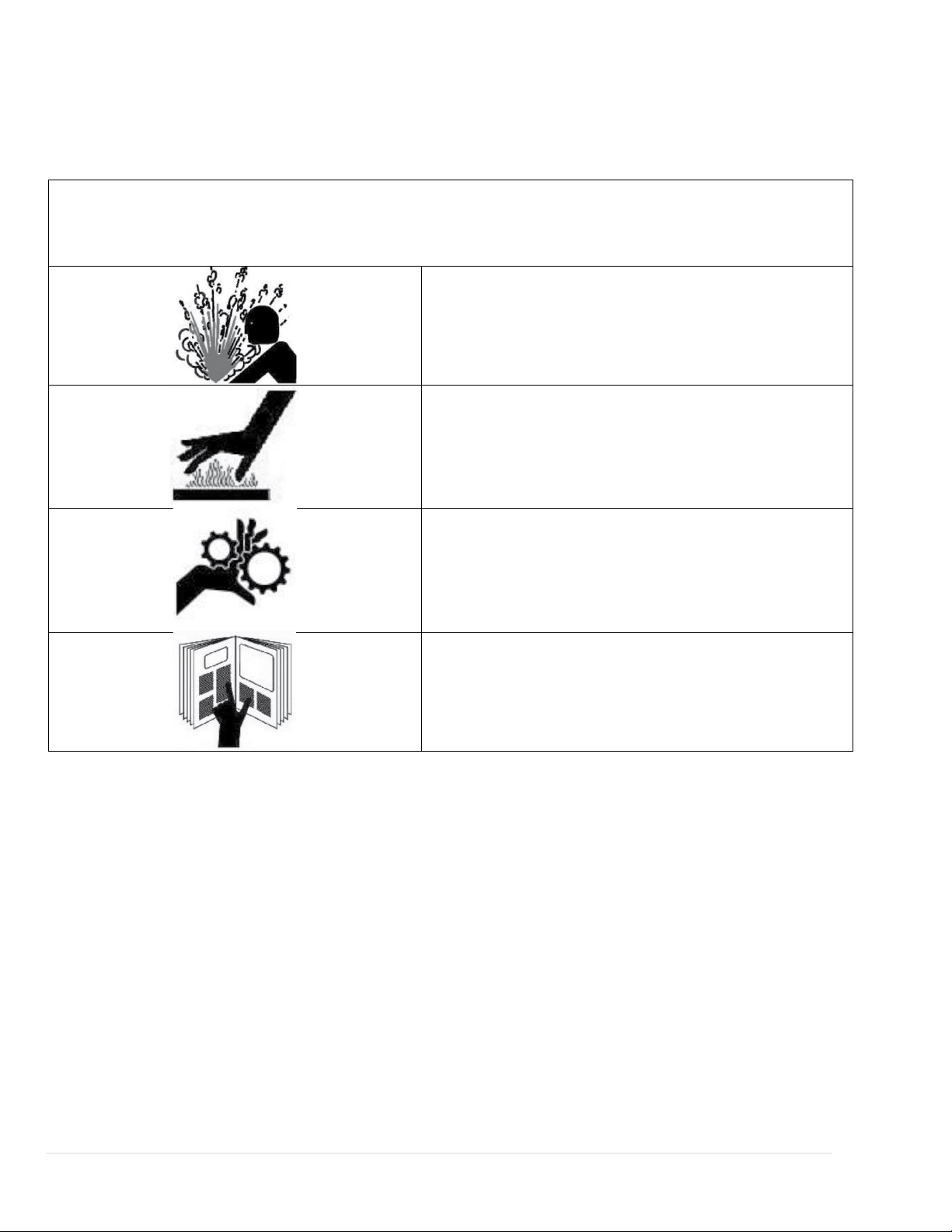
SAFETY PRECAUTIONS
DANGER
EXPLOSION HAZARD
Never operate the machine in an explosive
atmosphere, near combustible materials, or
where ventilation does not clear exhaust fumes.
WARNING
BURN HAZARD
Never come into contact with the engine or
muffler when engine is operating or shortly after it
is turned off. Serious burns may occur.
CAUTION
MOVING PARTS
Before starting the machine, ensure that all
guards and safety devices are in place and
functioning properly.
ATTENTION
READ OWNER’S MANUAL
Read and understand owner’s manual before
using this machine. Failure to follow operating
instructions could result in serious injury or death.

Predator 2400
Owner’s Manual
OIPB-IO-2003-P2400 GRINDER 4 | P a g e 0 1 / 1 7 / 2 0 19
TABLE OF CONTENTS
INTRODUCTION 5
SPECIFICATIONS 5
WARRANTY INFORMATION 6
SAFETY PRECAUTIONS 7
OPERATION INSTRUCTIONS 8
MAINTENANCE 10
TROUBLESHOOTING ERROR! BOOKMARK NOT DEFINED.
FAULTS WHICH CANNOT BE AUTOMATICALLY RESET 11
PARTS DRAWINGS & DIAGRAMS 13
BELT
TENSIONING
GUIDE
14
BELT
ROUTING
PATH
31
DECLARATION OF CONFORMITY 32

Predator 2400
Owner’s Manual
OIPB-IO-2003-P2400 GRINDER 5 | P a g e 0 1 / 1 7 / 2 0 19
INTRODUCTION
Innovatech Products and Equipment Company specializes in the manufacturing and
distribution of surface preparation equipment and supplies. From our early origins as a flooring
removal company, and a foundation based upon the success of our Terminator line of flooring
removal machines, Innovatech has transformed itself into an industry leader over a twelve-
year period.
Our continued growth can be attributed to our pledge to offer only premium products, our
commitment to stand behind what we sell, and a staff well known throughout the industry for
their knowledge and commitment to our valued customers. Based on customer need,
Innovatech has proudly diversified our offerings to include a complete line of surface
preparation products including Shot Blasters, Scarifiers, Floor Grinders, Dust Collectors,
Diamond Abrasives, and other products.
SPECIFICATIONS
2400 (7.5 hp)
2400 (10 hp)
Cutting Width
24” (609mm)
24” (609mm)
Dimensions (Operating
Conditions)
49” x 25” x 46”
(1244mm x 635mm x
1168mm)
49” x 25” x 46”
(1244mm x 635mm x
1168mm)
Weight
568lbs (258kg)
652lbs (296kg)
Tank Capacity
6 Gal (22.75L)
6 Gal (22.75L)
Grinding Discs
Dimensions
4”x 8.5” (101mm x 216mm)
4” x 8.5” (101mm x 216mm)
Motor
HP
7.5
10
RPM
180–900rpm
180–900rpm
Power Source
Phase
1 Øor 3 Ø
3 Ø
Voltage
1Ø(208-230) 3Ø(208-230)
390-460
Hz
60Hz
60Hz
Amps
0-28A
40-36A
Extension Cord
50 Feet
50 Feet

Predator 2400
Owner’s Manual
OIPB-IO-2003-P2400 GRINDER 6 | P a g e 0 1 / 1 7 / 2 0 19
WARRANTY INFORMATION
Innovatech warrants to original retail purchaser of the equipment:
A. LIMITED WARRANTY
The equipment, when first delivered, will conform to the specifications set forth in the
Owner’s Manual and will be without defect in material or workmanship. For a period of
one (1) year after delivery to the original retail purchaser, or 300 clock hours of
operation, whichever occurs first; or in the case of replacement parts other than belts,
for a period of ninety (90) days after the part is installed or within the warranty period
described above, whichever is later, if the original retail purchaser notifies Innovatech
(either directly or through one of Innovatech’s authorized dealers) of a defect in material
or workmanship or of a non-conformity to the specifications, then, upon confirmation of
the defect of non-conformity and confirmation that the defect or nonconformity is
covered within these Limited Warranty conditions, Innovatech will, at its election and at
its expense, either (i) repair or correct the defect and/or non-conformity, or (ii) replace
the part.
B. LIMITATIONS
This Limited Warranty does not apply to damage caused by (i) misuse of the equipment
including, with limitation, use of the wrong power source, striking an imbedded object
such as a bolt, electrical outlet box, expansion joint or steel reinforcing rod; or (ii)
unauthorized alteration, modification, repair or tampering; or (iii) use of replacement
parts not supplied by Innovatech; or (iv) normal wear, discoloration, surface corrosion,
deterioration of finishes or paint surfaces, or (v) other appearance deterioration caused
primarily by use. Innovatech shall not be responsible and this Limited Warranty shall not
apply to damage caused by improper maintenance or failure to inspect and maintain the
equipment as recommended in the Owner’s Manual.
C. BELTS
The Drive Belt is covered as set out at paragraph A., above, but for the period of six (6)
months after delivery or 250 clock hours of operation, whichever occurs first.
D. TRANSPORTATION
Purchaser will pay the cost of transporting defective or non-conforming parts to
Innovatech and the cost of returning repaired or replacement parts to purchaser. Each
party will safely package the parts it sends to the other in accordance with good
commercial practice. If purchaser requests and Innovatech agrees, Innovatech may
perform covered warranty work where the equipment is located. If Innovatech performs
the work at the location, purchaser will pay the cost of business class transportation and
good quality meals and lodging for Innovatech’s technicians.
E. ABUSE
Innovatech is not responsible for damage, defect, breakage, or malfunction of the
equipment that is caused by abuse or by operation of the equipment in a manner which
is not recommended or approved by Innovatech.

Predator 2400
Owner’s Manual
OIPB-IO-2003-P2400 GRINDER 7 | P a g e 0 1 / 1 7 / 2 0 19
F. EXCLUSIVE WARRANTY
Except as is expressly set out in this limited warranty: (i) Innovatech makes no promise
or warranty, expressed or implied, with respect to the equipment; (ii) Innovatech makes
no promise or warranty that the equipment is fit for any particular purpose; (iii)
Innovatech will have no obligation or liability to the purchaser or to any third party with
for any damage caused by the equipment or as a result or consequence of any claimed
defect in the equipment, any failure to warn or notify, or any claimed non-conformity to
the specifications; and (iv) Purchaser will have no other remedies in respect of such
defect, non-conformity, damage or condition except those set out in this limited
warranty.
SAFETY PRECAUTIONS
1. Only persons who have received training are permitted to operate or repair the grinder.
2. Use personal safety equipment such as steel toe shoes, safety glasses, and earplugs.
3. Do not use grinder in area where there is a risk of explosion or fire.
4. Do not start the machine with heads off the ground.
5. Make sure the splashguard is on before stating machine.
6. Before you start grinding, check the floor for bolts, large holes and uneven joints. Hitting
these things can damage machine, tools, and cause personal injury.
7. Make sure all power supply is connected with the right voltage.
8. Use only cold water in water tank. Do not use chemicals in water tank.
9. When filling water tank, to avoid electrical hazards and injury, do not spill water onto the
machine motor and electrical box.
10.Switch off the machine power before changing grinding tools.
11.Disconnect power supply before working or repairing machine.
12.Be very careful with rolling machine on any sloping floors or ramps. The machine can
roll very quickly. Two people may be needed to handle and control the machine.
13.Use caution with removing the grinding tools after finished grinding. Tools can be very
hot. Use gloves to remove the plates.
14.When grinding glues, epoxy paints, or coatings, leaving the machine down on floor
could cause the head to stick to the floor. Always tip back machine as soon as the head
comes to a complete stop.
15.Always store machine in a dry place.
16.Only use Innovatech recommended tooling.
17.The operator must never leave the machine unattended during operation.
18.When grinding dry, use a suitable vacuum to extract the dust.
19.Innovatech is not responsible for any off gassing of hazardous gas that is generated by
grinding materials. It is the responsibility of the operator. Grinding floors containing
asbestos is especially dangerous and can cause health problems. Contact your state or
country for the proper way to handle it.

Predator 2400
Owner’s Manual
OIPB-IO-2003-P2400 GRINDER 8 | P a g e 0 1 / 1 7 / 2 0 19
Controls and Features
A. Lamp light is red, power is on ready to use
B. Emergency stop push down to stop and pull up to restart
C. Forward and reverse
D. Manual speed pot: controls the rotation of the grinding head. Turn the knob clockwise
to increase the speed and counter clockwise to decrease the speed
NOTE: DO NOT use the emergency stop button to start and stop the machine. This button is
designed for emergency use only.

Predator 2400
Owner’s Manual
OIPB-IO-2003-P2400 GRINDER 9 | P a g e 0 1 / 1 7 / 2 0 19
OPERATION INSTRUCTIONS
Before starting:
1. Check the floor carefully and remove all bolts, nails, as well as any loose material that
could get caught in the machine.
2. Fit the appropriate tools to the machine.
3. Fit splash guard to the right height.
4. Connect the power supply. Make sure you have all the phases. May have to check with
volt meter.
5. If you are grinding dry, connect the appropriate vacuum and start vacuum before
starting the grinder.
Starting machine:
1. Turn main power switch on side of power box to ON.
2. Turn forward or reverse switch left of right.
3. Turn manual speed pot up to get the heads turning for desired speed. (If heads do not
move, you may have to lean on handle to reduce pressure on tools.
4. Always grip handle firmly when starting machine. The machine will always move from
side to side with first start.
5. When finished with grinding, turn off machine and let the heads come to a complete
stop before tilting back the machine.
Changing of Tools:
1. Before working on the grinder, bring the motor to a total stop and disconnect power.
2. Tilt machine back on floor.
3. Use caution! Tools can be very hot from grinding. Use gloves.
4. Use special tool supplied to turn center of tool holder to remove tool plate.
5. Replace with new tool plate and turn to lock in place.
6. Lower machine back down and re-adjust splash guard is necessary.
NOTE: IF THE WRONG POWER IS SUPPLIED TO THE GRINDER, IT WILL DAMAGE
THE ELECTRICAL COMPONENTS IN THE INVERTERS.

Predator 2400
Owner’s Manual
OIPB-IO-2003-P2400 GRINDER 10 | P a g e 0 1 / 1 7 / 2 0 19
MAINTENANCE
Clean machine after every use. To clean machine, use a low pressure water hose or air
pressure. Do not use a high PSI pressure washer. This could force water into areas of the
machine unintentionally and damage parts. A regular inspection of machine for wear and
damage should be done on a regular basis. If any parts have been damaged or have
excessive wear, they should be replaced. If a belt needs being replaced, please see separate
instructions.
TROUBLESHOOTING
1. Check to see if main power supply is on.
2. Check to see if emergency stop is pushed down; if it is, pull up.
3. Check to see if manual speed pot is turned up past 1.
4. Check all cords ends for loose connection.
5. Check fuse in distribution box with test meter.
6. Check to see if all phases are with right voltage (check with volt meter).
7. Check the converter connector cable to motor.
8. Check for error message on display of the converter.

Predator 2400
Owner’s Manual
OIPB-IO-2003-P2400 GRINDER 11 | P a g e 0 1 / 1 7 / 2 0 19
FAULTS WHICH CANNOT BE AUTOMATICALLY RESET
Faults which cannot be automatically reset are listed in the table below. To clear these faults:
1. Remove power from the drive controller.
2. Wait for the display to go off completely.
3. Determine the cause of the fault and correct it.
4. Re-apply power.
FAULT
PROBABLE CAUSE
REMEDY
B L F
Brake Sequence
•Brake release current not reached
•Check the drive controller and motor
connections
•Check the motor windings
C r F
Precharge Circuit
Fault
•Precharge circuit damaged
•Reset the drive controller
•Replace the drive controller
I n F
Internal Fault
•Internal fault
•Internal connection fault
•Remove sources of electromagnetic
interference
•Replace the drive controller
O C F
Over Current
•Incorrect parameter settings in the
Set- and drC- menus
•Acceleration too rapid
•Drive controller and/or motor
undersized for load
•Mechanical blockage
•Clear the mechanical blockage
S C F
Motor Short Circuit
•Short circuit or grounding at the
drive controller output
•Significant ground leakage current
at the drive controller output if
several motors are connected in
parallel
•Check the cable connecting the drive
controller to the motor and check the motor
insulation
•Reduce the switching frequency
S O F
Over Speed
•Instability
•Overhauling load
•Check the size of the motor, drive controller,
and load
F n F
Aut-Tuning Fault
•Motor or motor power not suitable
for the drive controller
•Motor not connected to the drive
controller
•Check the presence of the motor during auto-
tuning
•If a downstream contractor is being used,
close it during auto-tuning
E P F
External Fault
•User defined
•User defined
L F F
•Loss of the 4-20 mA reference on
input A13
•Check the connection on input A13
•Loss of 4-20 mA follower
O b F
Over voltage during
deceleration
•Braking too rapidly
•Overhauling load
•Increase the deceleration time
O H F
Drive Overload
•Drive controller or ambient
temperature is too high
•Continuous motor current load is
too high
•Check the motor load, the drive controller
ventilation, and the environment. Wait for the
drive controller to cool before restarting
O L F
Motor Overload
•Thermal trip due to prolonged
motor overload
•Allow the motor to cool before restarting

Predator 2400
Owner’s Manual
OIPB-IO-2003-P2400 GRINDER 12 | P a g e 0 1 / 1 7 / 2 0 19
•Motor power rating too low for the
application
O P F
Motor phase failure
•Loss of phase at drive controller
output
•Downstream contractor open
•Motor not connected
•Instability in the motor current
•Drive controller oversized for motor
•Check the connections from the drive
controller to the motor
•Test the drive controller on a low power
motor or without a motor: set OPL to nO
O S F
Over voltage during
steady state
operation or during
acceleration
•Line voltage too high
•Line supply transients
•Check the line voltage. Compare with the
drive controller nameplate rating
•Reset the drive controller
P H F
Input phase failure
•Input phase loss, blown fuse
•Three-phase drive controller used
on a single-phase line supply
•Input phase imbalance
•Transient phase fault
NOTE: This protection only operates
with the drive controller running
under load
•Check the connections and the fuses
•Verify that the input power is correct
•Supply three-phase power if needed
C F F
Configuration Fault
•The parameter configurations are
not suited to the application
•Restore the factory settings or load the
backup configuration, if it is valid
U S F
Under Voltage
•Line supply too low
•Transient voltage dip
•Damaged precharge resistor
•Check the line voltage
•Replace the drive controller

Predator 2400
Owner’s Manual
OIPB-IO-2003-P2400 GRINDER 13 | P a g e 0 1 / 1 7 / 2 0 19
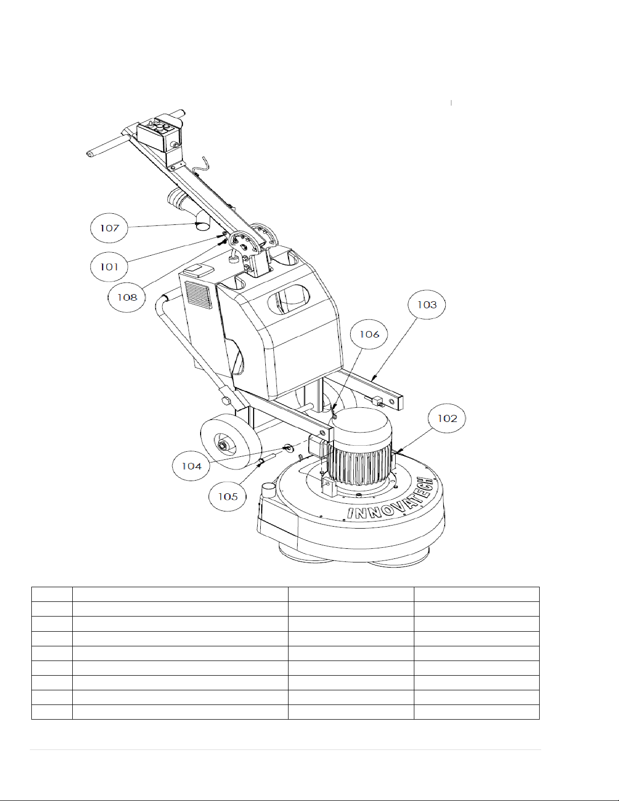
PARTS DRAWINGS & DIAGRAM
Grinder Final Assembly
10 hp, 3-Phase motor Part# 96-0083/ 7.5 hp, 1-Phase motor Part# 96-0084
ITEM
DES
CRIPTION
PART#
QTY
101
Washer (split
lock)
,
3/
8
11-0129
2
102
G
r
i
nder
head
assy
see note
2
1
103
Frame assy
(complete
bu
i
ld
-
up
)
see note
2
1
104
Washer, 5/8
1
1-0
148
2
105
Pin
(clevis),
5/8
dia.
x 2-1/2
long
11
-
0082
2
106
Pin
(hairpin
cotter)
11
-0052
2
107
Coupler Y connector
53-0332
1
108
Screw (Hex head), 3/8-16 x 3/4
11-0130
2
Predator 2400
Owner’s Manual
OIPB-IO-2003-P2400 GRINDER 14 | P a g e 0 1 / 1 7 / 2 0 19
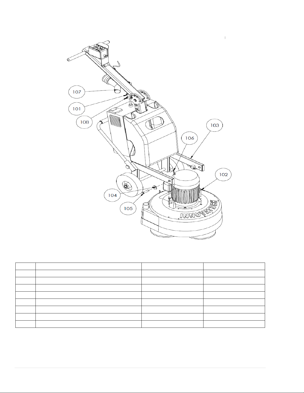
98-0005 10HP, 230V
ITEM
DES
CRIPTION
PART#
QTY
101
Washer (split
lock)
,
3/
8
11-0129
2
102
G
r
i
nder
head
assy
96-0077
1
103
Frame assy
(complete
bu
i
ld
-
up
)
98-0081
1
104
Washer, 5/8
1
1-0
148
2
105
Pin
(clevis),
5/8
dia.
x 2-1/2
long
11
-
0082
2
106
Pin
(hairpin
cotter)
11
-0052
2
107
Coupler Y connector
53-0332
1
108
Screw (Hex head), 3/8-16 x 3/4
11-0130
2
Predator 2400
Owner’s Manual
OIPB-IO-2003-P2400 GRINDER 15 | P a g e 0 1 / 1 7 / 2 0 19
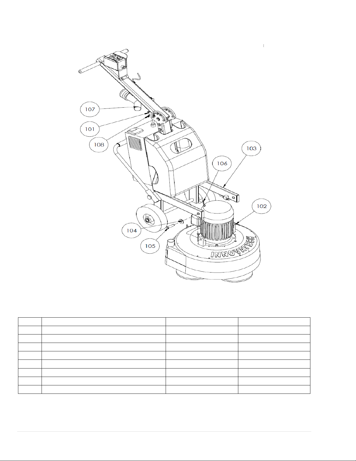
98-0006 7.5HP, 230V
ITEM
DES
CRIPTION
PART#
QTY
101
Washer (split
lock)
,
3/
8
11-0129
2
102
G
r
i
nder
head
assy
96-0078
1
103
Frame assy
(complete
bu
i
ld
-
up
)
96-0082
1
104
Washer, 5/8
1
1-0
148
2
105
Pin
(clevis),
5/8
dia.
x 2-1/2
long
11
-
0082
2
106
Pin
(hairpin
cotter)
11
-0052
2
107
Coupler Y connector
53-0332
1
108
Screw (Hex head), 3/8-16 x 3/4
11-0130
2
Predator 2400
Owner’s Manual
OIPB-IO-2003-P2400 GRINDER 16 | P a g e 0 1 / 1 7 / 2 0 19
98-0007, 10HP, 480V
ITEM
DES
CRIPTION
PART#
QTY
101
Washer (split
lock)
,
3/
8
11-0129
2
102
G
r
i
nder
head
assy
96-0077
1
103
Frame assy
(complete
bu
i
ld
-
up
)
96-0091
1
104
Washer, 5/8
1
1-0
148
2
105
Pin
(clevis),
5/8
dia.
x 2-1/2
long
11
-
0082
2
106
Pin
(hairpin
cotter)
11
-0052
2
107
Coupler Y connector
53-0332
1
108
Screw (Hex head), 3/8-16 x 3/4
11-0130
2

Predator 2400
Owner’s Manual
OIPB-IO-2003-P2400 GRINDER 17 | P a g e 0 1 / 1 7 / 2 0 19
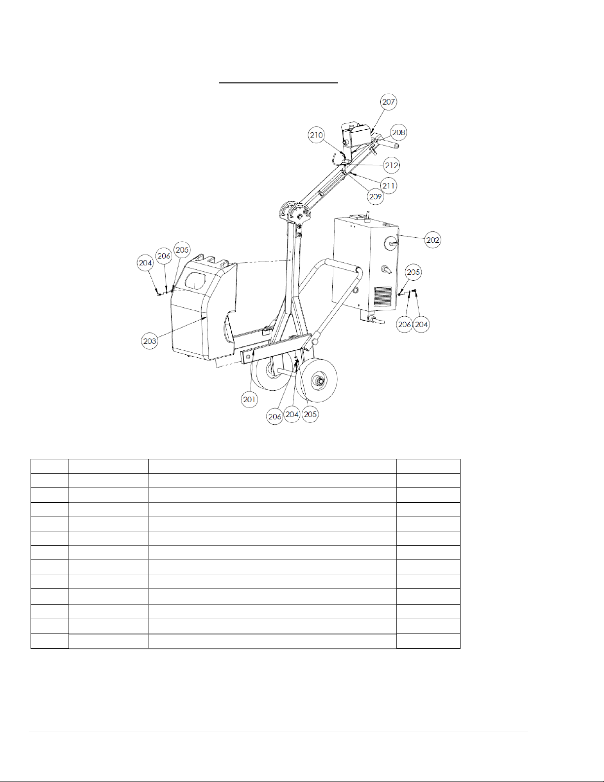
96-0081 Frame 2400
(Complete Build-Up)
10 hp, 3-Phase motor Part# 96-0083
7.5 hp, 1-Phase motor Part# 96-0084
ITEM
PART
DESCRIPTION
QTY
201
96-0070
Frame structure
1
202
See note 2
Inverter Box
1
203
96-0071
Water tank assy
1
204
11-0118
Screw (hex head), 5/16-18 x3/4
8
205
11-0139
5/16 Washer
8
206
11-0127
5/16 Lock washer
8
207
23-0052
Power control box
1
208
53-0223
Bracket
1
209
13-0151
P-clamp (1/2” cable size)
2
210
11-0152
Screw (1/4 - 20 x 5/8 socket button head)
6
211
11-0217
Screw (5/16 - 18 x 3/4 socket button head)
2
Notes:
1. For illustration simplicity, not all duplicate items are shown or labeled
2. Inverter box, Power supply box and connecting cable are pre-wired together as one unit.
3. Inverter unit options: use Part# 96-0072 for 10 hp 3-phase motor and Part# 96-0073 for 7.5 hp 1-phase
motor
4. Inverter protection bar is part of the frame structure and is not shown
Predator 2400
Owner’s Manual
OIPB-IO-2003-P2400 GRINDER 18 | P a g e 0 1 / 1 7 / 2 0 19
96-0081, 10hp, 230V
ITEM
PART
DESCRIPTION
QTY
201
96-0070
Frame structure
1
202
96-0072
Inverter Box
1
203
96-0071
Water tank assy
1
204
11-0118
Screw (hex head), 5/16-18 x3/4
8
205
11-0139
5/16 Washer
8
206
11-0127
5/16 Lock washer
8
207
23-0052
Power control box
1
208
53-0223
Bracket
1
209
13-0151
P-clamp (1/2” cable size)
2
210
11-0152
Screw (1/4 - 20 x 5/8 socket button head)
6
211
11-0217
Screw (5/16 - 18 x 3/4 socket button head)
2
212

Predator 2400
Owner’s Manual
OIPB-IO-2003-P2400 GRINDER 19 | P a g e 0 1 / 1 7 / 2 0 19
96-0082, 7.5hp, 230V
ITEM
PART
DESCRIPTION
QTY
201
96-0070
Frame structure
1
202
96-0073
Inverter Box
1
203
96-0071
Water tank assy
1
204
11-0118
Screw (hex head), 5/16-18 x3/4
8
205
11-0139
5/16 Washer
8
206
11-0127
5/16 Lock washer
8
207
23-0052
Power control box
1
208
53-0223
Bracket
1
209
13-0151
P-clamp (1/2” cable size)
2
210
11-0152
Screw (1/4 - 20 x 5/8 socket button head)
6
211
11-0217
Screw (5/16 - 18 x 3/4 socket button head)
2
212
See note 2
Cable between control box and inverter
1

Predator 2400
Owner’s Manual
OIPB-IO-2003-P2400 GRINDER 20 | P a g e 0 1 / 1 7 / 2 0 19
96-0091, 10hp, 480V
ITEM
PART
DESCRIPTION
QTY
201
96-0070
Frame structure
1
202
96-0093
Inverter Box
1
203
96-0071
Water tank assy
1
204
11-0118
Screw (hex head), 5/16-18 x3/4
8
205
11-0139
5/16 Washer
8
206
11-0127
5/16 Lock washer
8
207
See note 2
Power control box
1
208
53-0223
Bracket
1
209
13-0151
P-clamp (1/2” cable size)
2
210
11-0152
Screw (1/4 - 20 x 5/8 socket button head)
6
211
11-0217
Screw (5/16 - 18 x 3/4 socket button head)
2
212
See note 2
Cable between control box and inverter
1
Other manuals for Predator 2400
1
Table of contents
Popular Sander manuals by other brands


Graphite
Graphite 59G244 instruction manual

Clarke
Clarke CONTRACTOR CON320 Operation & maintenance instructions

Ryobi
Ryobi ESS1813 Owner's operating manual

EINHELL
EINHELL BT-PO 1100 E Original operating instructions

Ryobi
Ryobi P450 Operator's manual

Dexter Laundry
Dexter Laundry 900BS2.5 instruction manual

Makita
Makita 9401 instruction manual

USC
USC DWE-6421 Operating procedures

Dynabrade
Dynabrade Dynabug 10278 Safety, operation and maintenance instructions

Ingersoll-Rand
Ingersoll-Rand 8416-B Series Operating and maintenance manual

WilTec
WilTec 61055 Operation manual

MIRKA
MIRKA AROS-B 150NV operating instructions