Innovatis cedex hires Manual

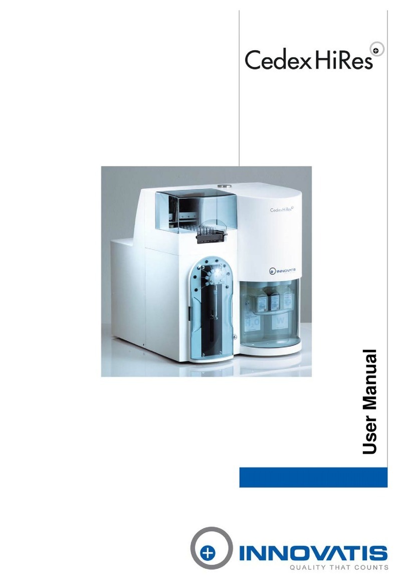
Cedex HiRes Analyzer Operator’s Guide
Software version 2.1


3
Table of Contents
Prologue 9
I. Revision History ................................................................................................................................................................ 9
II. Contact Addresses .......................................................................................................................................................... 9
III. Declaration of Conformity.........................................................................................................................................10
IV. Warranty ..............................................................................................................................................................................10
V. Trademarks ........................................................................................................................................................................10
VI. Copyrights ..........................................................................................................................................................................10
VII. Intended Use.....................................................................................................................................................................10
VIII. Preamble .............................................................................................................................................................................11
IX. Contents of this Operator’s Guide ........................................................................................................................11
X. Conventions used in this Guide .............................................................................................................................11
XI. FCC Notification..............................................................................................................................................................12
XII. Warnings and Precautions........................................................................................................................................13
XIII. Disposal of the Analyzer ............................................................................................................................................14
A Overview 15
1 Description of the Cedex HiRes System ...........................................................................................................16
2 The Measurement Procedure.................................................................................................................................. 17
3 Data Analysis ..................................................................................................................................................................18
4 Technical Specifications of the Analyzer..........................................................................................................19
B System Description 21
1 Installing the Cedex HiRes System......................................................................................................................21
1.1 Completing the Windows Mini-setup ........................................................................................................................21
1.2 Configuring Access to the Cedex HiRes Software for Windows User Accounts ......................................22
2 Choosing a Suitable Location.................................................................................................................................27
3 Starting the Cedex HiRes System after Installation ...................................................................................27
4 Securing Access Rights ............................................................................................................................................28
4.1 Access Control at the Windows Operating System Level...................................................................................28
4.2 Access Control at the Cedex HiRes System Software Level..............................................................................28

4Cedex HiRes Analyzer Operator’s Guide
Table of Contents
C Operation 29
1 Overview of the Cedex Control Center...............................................................................................................29
1.1 Menu Bar ..............................................................................................................................................................................29
1.2 System Menu.......................................................................................................................................................................29
1.3 Measurement Menu .........................................................................................................................................................30
1.4 Functions Menu..................................................................................................................................................................30
1.5 Reports Menu ....................................................................................................................................................................31
1.6 Master Data Menu ............................................................................................................................................................31
1.7 Setup Menu .........................................................................................................................................................................31
1.8 Help Menu............................................................................................................................................................................32
1.9 Shortcut Area ......................................................................................................................................................................32
1.10 Tracking of Status of Events Carried out by the Analyzer ..................................................................................32
2 Preparing the Analyzer for Measurements......................................................................................................33
2.1 Switching on ........................................................................................................................................................................33
2.2 Logging in at the Computer Operating System Level ..........................................................................................33
2.3 Starting the Cedex HiRes Software 2.1 ....................................................................................................................33
2.4 Performing a HW Startup and Prime..........................................................................................................................34
2.5 Preparing the Reagent Kit ..............................................................................................................................................35
2.5.1. Installing or Changing the Reagent Kit ....................................................................................................................35
2.5.2. Refilling Containers Individually ..................................................................................................................................36
2.6 Checking the Analyzer..................................................................................................................................................... 37
3 Carrying out a Single Measurement ...................................................................................................................38
3.1 Opening the Measurement window and specifying the Operating Mode and Sample Data ..............39
3.2 Defining the Measurement and Analysis (Process) Parameters .....................................................................40
3.3 Preparing the Sample and Attaching it to the Multi Sample Tray or Sample Port....................................41
3.3.1. Starting the Measurement .............................................................................................................................................41
3.3.2. End of Measurement........................................................................................................................................................42
3.4 Interrupting a Measurement..........................................................................................................................................43
4 Working with the Multi Sampler............................................................................................................................44
4.1 The Multi Sampler DefaultCup.....................................................................................................................................45
4.2 Preparing the Measurement..........................................................................................................................................46
4.2.1. Using the Multi Sample Tray..........................................................................................................................................46
4.2.2. Ejecting the Multi Sample Tray .....................................................................................................................................46
4.2.3. Performing a Prime............................................................................................................................................................46
4.3 Carrying out Measurements with the Multi Sampler........................................................................................... 47
4.3.1. The Multi Run Data Entry Window..............................................................................................................................47
4.3.2. Starting a Measurement .................................................................................................................................................47
4.3.3. Adding Measurements to the List while Measurements are Running .........................................................48
4.3.4. Disruption of Measurements.........................................................................................................................................49
4.3.5. Modifying Data Entry........................................................................................................................................................49
4.3.6. Non-Linear Measurements in a Sample Series .....................................................................................................49
4.3.7. Interrupting or Stopping a Measurement.................................................................................................................49
4.4 Results ...................................................................................................................................................................................50
4.4.1. The Multi Sampler Result Table (Print Report) .......................................................................................................50
5 Switching off the Cedex HiRes Analyzer...........................................................................................................51
5.1 Carrying out an LM Shutdown and HW Shutdown..............................................................................................51
5.2 Logging out ..........................................................................................................................................................................52
5.3 Shutting down the Control Center ..............................................................................................................................52

5
Table of Contents
D Software 53
1 Using the Measurement Results Window........................................................................................................53
1.1 Result Data area.................................................................................................................................................................54
1.2 Sample Parameters and Processing Parameters areas.......................................................................................55
1.3 Image Area...........................................................................................................................................................................56
1.3.1. Viewing Individual Cell Images.....................................................................................................................................56
1.3.2. Viewing a Cell Image Using the Image View Window ........................................................................................57
1.3.3. Excluding Images from the Evaluation Process/Including Excluded Images .............................................58
1.3.4. Viewing the Prescan Image ...........................................................................................................................................59
2 Using the Measurement List....................................................................................................................................60
2.1 Viewing Analysis Results ................................................................................................................................................60
2.2 Searching for Measurements........................................................................................................................................61
3 Editing Existing Analysis Results/Data Sets...................................................................................................62
3.1 The Reprocess Button......................................................................................................................................................62
3.2 Effective Data Sets ............................................................................................................................................................63
4 Graphical Display of the Analysis Results........................................................................................................64
4.1 Enlarging the Histograms ...............................................................................................................................................64
4.2 Aggregate Histogram.......................................................................................................................................................65
4.3 Cell Diameter Histogram................................................................................................................................................. 67
4.4 Object Diameter Histogram ...........................................................................................................................................68
4.5 Defining Diameter Intervals in the Diameter Histograms...................................................................................68
4.6 Compactness Histogram.................................................................................................................................................69
4.7 Measurement Statistics Histogram............................................................................................................................. 70
5 Cultivation Time Chart.................................................................................................................................................71
5.1 Creating a CTC View.........................................................................................................................................................71
5.1.1. The View Area .....................................................................................................................................................................72
5.1.2. The Series of Measurements Belonging to Selected View Area .....................................................................72
5.1.3. Adding Measurements to a View ................................................................................................................................73
5.1.4. Editing Measurements in a View ................................................................................................................................. 74
5.1.5. Viewing List of Measurements in a Series............................................................................................................... 74
5.1.6. Deleting Views and Series..............................................................................................................................................75
5.1.7. Exporting a View ................................................................................................................................................................75
5.2 Creating a Cultivation Time Chart ...............................................................................................................................75
5.2.1. The Data Selection Area .................................................................................................................................................76
5.2.2. Fitting to the Lowest Common Value ......................................................................................................................... 77
5.2.3. Measurement Series Offset ...........................................................................................................................................77
5.2.4. Variable Axis Calibration .................................................................................................................................................77
5.2.5. The Exponential Regression Button............................................................................................................................78
5.2.6. Printing out a Cultivation Time Chart ......................................................................................................................... 78
6 General Functions of the System ..........................................................................................................................79
6.1 Data Management ............................................................................................................................................................ 79
6.1.1. Printing Reports..................................................................................................................................................................79
6.1.2. Export to file.........................................................................................................................................................................80
6.2 Data Exchange....................................................................................................................................................................81
6.2.1. Export ....................................................................................................................................................................................81
6.2.2. Import.....................................................................................................................................................................................82
6.3 Viewing and Evaluating the Audit Trail File..............................................................................................................82
6.4 User Preferences................................................................................................................................................................83
6.4.1. Specifying Default Measurement Parameters ........................................................................................................83
6.4.2. Specifying Other Default Parameters.........................................................................................................................84
6.4.3. Specifying the Workarea for the Analysis Data......................................................................................................84
6.5 Changing own Password ................................................................................................................................................84

6Cedex HiRes Analyzer Operator’s Guide
Table of Contents
D Software continued
7 Administrator Functions.............................................................................................................................................85
7.1 Administration of User Accounts.................................................................................................................................85
7.1.1. Creating User Accounts .................................................................................................................................................85
7.1.2. Assigning Access Rights ...............................................................................................................................................86
7.1.3. Creating user groups........................................................................................................................................................ 87
7.1.4. Editing and Deleting User Accounts .......................................................................................................................... 87
7.1.5. Creating and Editing User roles ...................................................................................................................................88
7.2 Password Management...................................................................................................................................................89
7.2.1. Specifying Password Characteristics..........................................................................................................................89
7.2.2. Assigning New Passwords.............................................................................................................................................89
7.3 Assigning Work Areas......................................................................................................................................................90
7.4 The System Options ..........................................................................................................................................................91
7.4.1. Automatically Start the Hardware Management ...................................................................................................91
7.4.2. Modifying the Standard Setting for the Multi Sampler DefaultCup...............................................................92
7.4.3. Turning off Automatic Incrementation of Sample Cup Position.......................................................................92
7.4.4. Turning off the Flow Chamber Prescan.....................................................................................................................93
7.4.5. Error Level Displayed to Users......................................................................................................................................94
7.4.6. Liquid Container Configuration....................................................................................................................................94
7.4.7. Default Settings..................................................................................................................................................................94
7.5 Adjustment of the Image Analysis using the Live Operator .....................................................................................95
7.5.1. Description of the Cell Type List and Live Operator .............................................................................................96
7.5.2. The Cell Type List Window..............................................................................................................................................96
7.5.3. Creating a New Cell Type................................................................................................................................................97
7.5.4. Editing an Existing Cell Type..........................................................................................................................................98
7.5.5. Viewing an Existing Cell Type........................................................................................................................................98
7.5.6. Deleting an existing Cell Type.......................................................................................................................................99
7.5.7. Working with the Live Operator....................................................................................................................................99
7.5.8. Description of the Individual Operator Parameters ........................................................................................... 101
7.6 Archiving Data .................................................................................................................................................................103
7.6.1. Archive.................................................................................................................................................................................103
7.6.2. Restore................................................................................................................................................................................ 104
7.6.3. Deleting Archived Data ................................................................................................................................................ 104

7
E Maintenance and Care 105
1 Cleaning and Maintenance Check List............................................................................................................105
2 Scheduling Automatic Cleaning Routines .................................................................................................... 106
3
Daily and Manual Maintenance and Cleaning Routines .......................................................................... 107
3.1 Checking the Reagent Containers when Manually Refilling .........................................................................107
3.2 Cleaning Routines Carried out by the Liquid Management........................................................................... 108
3.2.1. Cleaning Options ............................................................................................................................................................ 108
3.2.2. The Hardware Management Window ......................................................................................................................110
3.2.3. Carrying out a Cleaning Routine................................................................................................................................110
3.2.4. Interrupting/Terminating a Cleaning Routine........................................................................................................110
3.3 Scanning the Chamber to Verify the Effectiveness of Cleaning Routines ................................................110
4 Automatic Adjustment and Alignment Verification ..................................................................................112
5 Syringe Maintenance.................................................................................................................................................114
5.1 Removing the Syringe ....................................................................................................................................................114
5.2 Assembling and Installing the Syringe ....................................................................................................................115
5.3 Maintenance of the Syringe Guide and Spindle..................................................................................................116
6 Maintenance of the Flow chamber, 8-Way Valve and the remaining Hardware
Components....................................................................................................................................................................117
7 Operational Data ..........................................................................................................................................................117
8 The System Suitability Test (SST) ......................................................................................................................118
8.1 Creating SST Checkpoints............................................................................................................................................118
8.1.1. Creating SST Checkpoints With and Without Measurements........................................................................118
8.1.2. Running a Water Blank ................................................................................................................................................120
8.1.3. Setting up the SSTFailureReaction in the System Options Menu .................................................................120
8.2 Performing an SST...........................................................................................................................................................121
8.2.1. Performing an SST with Measurements .................................................................................................................121
8.2.2. Performing an SST without Measurements...........................................................................................................122
8.3 Tracking Trends in SST Results over Time..............................................................................................................123
8.3.1. Tracking Trends in SST Checkpoints with Measurements...............................................................................123
8.3.2. Tracking SST Checkpoints without Measurements ...........................................................................................125
8.4 Locking – Unlocking the System................................................................................................................................126
F Troubleshooting 127
1 Diagnosis of the Cedex HiRes Analyzer..........................................................................................................127
2 Trace and Logging........................................................................................................................................................128
3 The System Audit Trail File......................................................................................................................................128
G Appendix 129
1 System Options und User Preferences ............................................................................................................129
2 Index................................................................................................................................................................................... 140
Table of Contents

8Cedex HiRes Analyzer Operator’s Guide

9
Prologue
Prologue
I. Revision History
Version Revision Date
1.0 October 2010
© Copyright 2010, Roche Diagnostics GmbH, all rights reserved.
Information in this document is subject to change without notice. No part of this document may be reproduced
or transmitted in any form or by any means, electronic or mechanical, for any purpose, without the express
written permission of Roche Diagnostics GmbH.
Questions or comments regarding the contents of this Operator’s Guide can be directed to the address below or
to your Roche Diagnostics representative.
Roche Diagnostics GmbH
Roche Applied Science
Customer Support
Nonnenwald 2
82377 Penzberg, Germany
Every effort has been made to ensure that all the information contained in the Cedex HiRes System Operator’s
Guide is correct at the time of printing.
However, Roche Diagnostics GmbH reserves the right to make any changes necessary without notice as part of
ongoing product development.
II. Contact Addresses
Manufacturer Roche Diagnostics Ltd.
Forrenstrasse
CH-6343 Rotkreuz
Switzerland
Distribution Roche Diagnostics GmbH
Sandhofer Straße 116
D-68305 Mannheim
Germany
Distribution in USA Roche Diagnostics
9115 Hague Road
PO Box 50457
Indianapolis, IN 46250
USA
Revision History

10 Cedex HiRes Analyzer Operator’s Guide
III. Declaration of Conformity
The instrument meets the requirements laid down in Council Directive 2004/108/ EC relating
to “Electromagnetic Compatibility” and Council Directive 2006/95/EC relating to “Low Voltage
Equipment”. The following standards were applied: IEC/EN 61326-1 (EMC) and IEC/EN 61010-1
(Safety).
UL 61010-1 Electrical Equipment for Measurement, Control and Laboratory Use; Part 1:
General Requirements CAN/CSA-C22.2 No. 61010-1 (Second Edition) — Safety Requirements
for Electrical Equipment
IV. Warranty
The warranty conditions are specified in the sales contract. Contact your Roche Diagnostics representative for
further information.
Any unauthorized modification of the Cedex HiRes Analyzer and/or the Cedex HiRes Software will result in
invalidity of the guarantee and service contract.
V. Trademarks
CEDEX and INNOVATIS are trademarks of Roche. Other brands or product names are trademarks of their
respective holders.
VI. Copyrights
Cedex HiRes Analyzer Operator’s Guide. Copyright© 2010 Roche Diagnostics GmbH, all rights reserved.
Operating instructions and manuals are protected by copyright. No part of this document may be reproduced,
edited or translated without prior written consent of Roche Diagnostics GmbH except as permitted under the
terms of the copyright.
VII. Intended Use
The Cedex HiRes Analyzer automatically determines the cell concentration and viability of cell suspensions for
the purpose of life science research only.
The Cedex HiRes Analyzer is for life science research only. Not for use in diagnostic procedures.
It was neither developed nor validated by the manufacturer for any kind of in vitro diagnostic application.
Declaration of Conformity

11
Prologue
VIII. Preamble
Before setting up operation of the Cedex HiRes Analyzer, it is important to read this Operator’s Guide thoroughly
and completely. Non-observance of the instructions contained herein or performing an operation not stated in
this Operator’s Guide could involve safety hazards.
IX. Contents of this Operator’s Guide
This Operator’s Guide describes the operation of the Cedex HiRes Analyzer. It contains the following chapters:
Chapter A Overview presents the specifications of the Cedex HiRes Analyzer.
Chapter B System Description contains the installation requirements of the Cedex HiRes Analyzer and a
description of the system’s components. This chapter also gives a short overview of the basic functions and
operation of the system.
Chapter C Operation describes the operating procedures for the Cedex HiRes Analyzer, including the correct
placement of the reagents and disposables and instructions for carrying out single and multiple measurements
of cell samples.
Chapter D Software provides a detailed description of the Cedex HiRes Analyzer software functions and
features.
Chapter E Maintenance and Care describes the maintenance and care procedures that are required for the
Cedex HiRes Analyzer.
Chapter F Troubleshooting contains troubleshooting information for the Cedex HiRes Analyzer.
Chapter G Appendix contains a detailed list of System Options and User Preferences and an index.
X. Conventions used in this Guide
Text Conventions
To present information consistently and memorably the following text conventions are used in this Operator’s
Guide:
Numbered list: Steps in a procedure that must be performed in the order listed.
Italic type: Used for operating instructions for the Cedex HiRes Software. In addition,
important notes and information notes are shown in italic type.
Blue italic type: Refers to a different section in this Operator’s Guide, which should be consulted.
Preamble

12 Cedex HiRes Analyzer Operator’s Guide
Symbols
In this Operator’s Guide the following symbols are used as visual signals:
Symbol Heading Description
WARNING This symbol is used to indicate that non-compliance with instructions or
procedures could lead to physical injury or even death or could cause
damage to the system.
IMPORTANT NOTE
Information critical to the success of the procedure or use of the product.
INFORMATION NOTE
Additional information about the current topic or procedure.
ccc Procedure continued on next page.
■End of procedure.
The following symbols appear on the analyzer
Symbol Heading Description
CE MARK The CE mark on the analyzer type plate indicates conformity with
requirements of the directives relevant for this analyzer.
DANGEROUS
ELECTRICAL VOLTAGE
On the back of the analyzer near the power box.
XI. FCC Notification
Changes or modifications to this unit not expressly approved by the party responsible for compliance may
void the user‘s authority to operate the equipment.
Note: This equipment has been tested and found to comply with the limits for a Class A digital device, pursuant
to Part 15 of the FCC Rules. These limits are designed to provide reasonable protection against harmful
interference when the equipment is operated in a commercial environment. This equipment generates, uses
and can radiate frequency energy and, if not installed and used in accordance with the instruction manual, may
cause harmful interference to radio communications. Operating this equipment in a residential area is likely to
cause harmful interference, in which case the user will be required to correct the interference at his own expense.
FCC Notification

13
Prologue
XII. Warnings and Precautions
Moving parts may cause hand injuries. Never use the Cedex HiRes Analyzer without the protective cover
on the Multi Sampler and Syringe Module.
It is important that the following safety instructions and guidelines be observed in order to ensure safe and
reliable operation of Cedex HiRes Analyzer:
cPlace the device on a dry and sturdy surface, free of vibrations.
cAvoid transporting the device as much as possible once it has been assembled.
cPrevent the device from getting wet.
cProtect the device from dust and smoke.
cDo not expose the device to direct sunlight.
cEnsure there is sufficient air circulation around the Cedex HiRes Analyzer during operation (particularly
around the computer and monitor).
cOperate within a constant temperature range of +10 to +40°C (+50 to +100°F).
cFor best performance it is recommended to keep the analyzer permanently on and only shut down the
software application on a regular basis.
cThe Cedex HiRes Analyzer should only be used with the supplied or specified devices (Cedex HiRes
Analyzer, Cedex HiRes Software, monitor, computer, Multi Sampler, Reagent Tray).
cDo not install any additional software on the corresponding computer.
cOnly trained personnel in a controlled laboratory environment should operate the Cedex HiRes Analyzer.
cAll services and repairs should be performed only by authorized service technicians.
cAlways ensure that there are sufficient reagents in the reagent containers.
cClean the containers before reusing them.
cAlways observe the safety regulations when handling Trypan Blue, Detergent, Cleaning Solution or acids
and bases.
cWaste contaminated with tissue or cells, e.g. sample cups, pipette tips, etc., must be disposed of according
to the recommended rules for handling biohazard materials.
cAny leaks in the Liquid Management system must be repaired immediately. Contact your distributor or
authorized service technician.
cAlways ensure that there is a sample cup attached to the single sample port or placed in the DefaultCup
position on the Multi Sample tray.
cOnly use Cedex Detergent for the cleaning process in the Liquid Management system.
cOnly use sample cups from Roche Diagnostics GmbH for the conveyance of cell samples to the sample
port.
Other sample cups can cause irreparable damage to the Cedex HiRes Analyzer!
cAlways wear protective clothing, particularly gloves, when handling samples.
cTo prevent damage to the flow chamber, no particles larger than 80 µm should enter the measurement
system.
cParticles (especially microcarriers) larger than 90 µm should not gain access into the analyzer because
they cause irreparable damage and render the device non-functional.
cDirt or dust particles should not gain access into the device.
cEnsure that all equipment required for sample preparation, e.g. sample cups, pipette tips, etc., are stored
in a dust-free environment since coarse dust particles can impair the flow chamber’s functionality.
cCheck that the sample cup is free of contamination before use. Only clean sample cups can guarantee
optimal functioning of the Cedex HiRes Analyzer.
Warnings and Precautions

14 Cedex HiRes Analyzer Operator’s Guide
cEnsure that the Trypan Blue solution is free of contamination, otherwise filter prior to use. Roche
Diagnostics GmbH recommends the use of the Cedex HiRes Reagent Kit.
cSecure your measurement data.
If the system has been upgraded from some previous version to Software version 2.1, it is possible that
some default settings in the System Options may have slightly different values than those described in this
Operator’s Guide. The settings described in this Operator’s Guide apply to systems on which Software version
2.1 has been installed as the original software.
The software and hardware of your Cedex HiRes System can differ from the information described here, but
this should not make a difference to the operational functions in general.
The manufacturer is not responsible or liable for any damages resulting from improper use or failure to
comply with the regulations in the Operating Instructions.
Electrical Safety
The Cedex HiRes Analyzer is designed in accordance with Protection Class I
(IEC). The chassis/
housing of the instrument is grounded to protection earth
(PE) by means of a cord. For protection
against electrical shock hazards, the instrument must be directly connected to an approved
power source
such as a three-wire grounded receptacle for the 110 V or 230 V line. Do not use
an ungrounded receptacle; have a qualified electrician replace the ungrounded receptacle with
a properly (PE) grounded receptacle in accordance with the local electrical code. Do not use an
extension. Any break in the electrical ground path, whether inside or outside the instrument,
could be hazardous.
Under no circumstances should the user attempt to modify or deliberately
defeat the safety
features of this instrument. If the power cord becomes
cracked, frayed, broken, or otherwise
damaged, replace it immediately with the equivalent part from Roche Diagnostics.
XIII. Disposal of the Analyzer
Disposal Recommendations
All electrical and electronic products should be disposed of separately from the municipal waste system. Proper
disposal of your old appliance prevents potential negative consequences for the environment and human health.
The analyzer must be treated as biologically contaminated hazardous
waste.
Decontamination (i.e.,
a combination of processes, including cleaning, disinfection
and/or sterilization) is required before
reuse, recycling or disposal.
Dispose of the analyzer according to local and/or laboratory regulations.
For more information contact your local Roche Support personnel.
Components of your control unit such as the computer, monitor, keyboard, etc. which are marked
with the crossed-out wheeled bin symbol are covered by the European Directive 2002/96/EC on
waste electrical and electronic equipment (WEEE) of the European Parliament and the Council of
January 27, 2003.
These items must be disposed of via designated collection facilities appointed by government or
local authorities.
For more information about disposal of your old product, please contact your city office, waste
disposal service or local Roche Support personnel.
Disposal Recommendations
It is left to the responsible laboratory organization to determine whether control unit components are
contaminated or not. If contaminated, treat in the same way as the analyzer.
Disposal of the Analyzer

15
Overview
A
A
A Overview
The Cedex HiRes Analyzer automatically determines the cell concentration and viability of cell suspensions.
The analysis is based on the Trypan Blue Exclusion Method whereby cell suspensions are stained and analyzed.
The data obtained allows for the evaluation of the overall state of the cell culture, including the specific growth
rate and doubling time of a cell population, as well as the documentation of the cultivation process.
The evaluation of the samples is based on automatically obtained digital images that are analyzed using analysis
software on a separate computer (Cedex HiRes Control Unit). All the necessary steps – from the staining of
the samples to the recording and evaluation of the image data – are automatically performed by the analyzer.
Recognition and differentiation of cells as either viable or dead is done under standardized conditions, which
provides very precise and objective results.
A variety of parameters, including Viable Concentration, Total Concentration,Viability, Total Object Count,
Average Compactness and Average Diameter are analyzed using result data from single images, as well as from
all of the selected images of a sample. Standard deviation (Std. Dev.) of the number of cells from image to image
is also calculated. In addition, the Aggregate Rate, which shows the percentage of the total number of cells that
appear in aggregates (clusters), is determined for both single images and all of the images. The use of a Live
Operator makes it possible to directly observe the effects on the analysis of a sample when the image analysis
software (Operator) is adjusted.
Graphical representations of the measurement results can be viewed in the Measurement Statistics Histogram,
Diameter Histogram, Compactness Histogram, Aggregate Histogram and Cultivation Time Chart. In
the Measurement Statistics histogram, individual images can be compared to give a better overview of the
distribution of the cells in the images. The Cell Diameter Histogram shows the diameter distribution of living
cells. The Object Diameter Histogram shows the diameter distribution of all objects detected such as cells,
debris, air bubbles and viable and dead cell aggregates. The deviation of the shape of living cells from that of an
ideal sphere is represented in the Compactness Histogram. The Aggregate Histogram provides an overview of
the amount and size of aggregation found in the cell culture.
The Cultivation Time Chart displays growth curves and cultivation parameters in a time- dependent manner.
The results of the Cultivation Time Chart can be separately printed out. For further processing of the results in
other programs, data export in formats such as Excel-compatible formats and CSV (Comma Separated Values,
generally applicable) is possible. The Cultivation Time Chart includes calculations for the doubling time [T]
and specific growth-rate [µ].
The Cedex HiRes Software 2.1 is operated on Windows®XP Professional. Secure data handling, as well as a
carefully designed user management system, guarantee compatibility with 21 CFR, Part 11. Access security for
the Cedex HiRes System has been stepped up. Access is only allowed for authorized persons. The workstation
can be automatically blocked after a certain number of consecutive entries of a false password via the Systems
Options. A warning message will appear before the last allowed attempt.

16 Cedex HiRes Analyzer Operator’s Guide
A
A1 Description of the Cedex HiRes System
The Cedex HiRes System consists of two functional units, the Analyzer (see Figure 1) and the Control Unit
(computer equipped with Cedex HiRes Software 2.1).
Preparation and processing of the samples takes place in the analyzer. The analysis software is installed on a
computer and controls the analyzer, as well as the analysis and evaluation of the images obtained.
Multi Sampler tray with sample cups
Syringe module with 8-way valve
Tray with the Cedex Reagent Kit
ON/OFF Switch
Figure 1: The Cedex HiRes Analyzer
The analyzer consists of two main components, the hardware for image capturing (scanner) and the Liquid
Management system.
The flow chamber is specially developed to allow for the analysis of a defined volume of cell suspension. The
Liquid Management system is responsible for staining the sample as well as for filling and cleaning the flow
chamber and liquid feed system.
The volumes of sample and dye, as well as specific cleaning solutions required for each cleaning routine, are
precisely controlled via the syringe module with the 8-way distribution valve. The individual components of the
Liquid Management system are easily accessible to allow for trouble-free maintenance and control.
Description of the Cedex HiRes System

17
Overview
A
A
2 The Measurement Procedure
The determination of the number of viable cells (cells/ml) and viability of cell suspensions (the percentage of
viable cells from the total cell sample) is a fully automated, standardized procedure based on the manual Trypan
Blue Exclusion Method. A defined volume of Trypan Blue is added by the syringe to the sample cup containing
the cell suspension. The cell suspension and dye are optimally mixed between the syringe and sample cup by
controlled pump actions and then incubated for exactly the same amount of time for each measurement. This
minimizes effects on the viability measurements that might be caused by the toxicity of the Trypan Blue.
After the incubation period, the stained cell suspension in the syringe is then transported in one portion via
the capillary tubes and the 8-way valve into the precision flow chamber, an image of which is scanned with the
scanner. The scanned image of the flow chamber is then cut up into smaller images for evaluation.
Once the measurement procedure is completed, a cleaning routine is automatically performed by the Liquid
Management system. It is only possible to begin a new measurement after the cleaning routine has finished.
The Trypan Blue Exclusion Method
The Trypan Blue Exclusion Method is based on the principle that viable cells will not take up the dye, while
dead or dying cells have a compromised membrane that allows for the uptake of the dye. Thus, dead cells will
appear darkly stained.
Trypan Blue has a greater affinity for serum proteins than cellular proteins. If the image has a dark background
due to high quantities of stained serum proteins, centrifuge the cell sample and resuspend it in a protein-free
medium or physiological saline solution prior to counting.
The Measurement Procedure

18 Cedex HiRes Analyzer Operator’s Guide
A
A3 Data Analysis
The analysis software and its graphical user interface (GUI), known as the Cedex Control Center, enables
the user to work with Cedex HiRes Analyzer. The image analysis software (Operator) recognizes structures
and identifies particles, thus differentiating cells from cell debris and dirt particles. Live and dead cells are
differentiated according to their degree of Trypan Blue staining.
The image processing is integrated in the Cedex Control Center in such a way that the user or Administrator
can check on its function in the system. The analysis process cannot be altered during data recording in order
to allow for consistent and objective measurement results.
Data Analysis

19
Overview
A
A
4 Technical Specifications of the Analyzer
Cedex HiRes Analyzer
Method of measurement Digital image and pattern recognition
Viable/dead cell differentiation Trypan Blue Exclusion Method
Detectable cell concentration range 5 × 10⁴ – 1 × 10⁷cells per ml
Detectable cell diameter range 2 µm – 40 µm
Detectable object diameter range 1 µm – 90 µm
Required sample volume 300 µl
Average measurement period < 4.0 min
Geometric resolution 0.8 µm/Pixel
Chamber height 100 µm
Material and diameter of the capillaries Teflon, 765 µm
Operating temperature
(Optimal image quality is achieved
between 20°C and 30°C)
+10 to +40°C (+50 to +100°F)
Maximum temperature change 5°C per hour
Maximum humidity deviation 5% per hour
Operating humidity 20% – 80% relative humidity
(non-condensing)
Dimensions Height: 470 mm
Width: 405 mm
Depth: 505 mm
Weight with Multi Sampler: 28.9 kg
Weight without Multi Sampler: 26.9 kg
Energy requirements 100 – 250 VAC, 50 – 60 Hz
Energy consumption 24 VDC 2.0 A
Pollution Degree 2 (according to IEC 61010-1)
Installation Category II (according to IEC 61010-1)
Technical Specifications of the Analyzer

20 Cedex HiRes Analyzer Operator’s Guide
A
AHardware Requirements for the Cedex HiRes Control Unit
Computer x86-Architecture, Intel Pentium IV
minimum 2 GHz required, 3 GHz recommended
Operating system Windows®XP Professional
RAM Minimum 1 GB RAM
Hard-disk storage 100 MB free hard-disk storage for installation of application.
Minimum 20 GB free hard-disk storage for data storage of
approx. 1000 measurements
Recommended 80 GB
USB 2 free ports
Firewire 1 free port
(400 Mbps, with 4 or 6 contacts)
CD/DVD burner Minimum CD burner required, DVD burner recommended if
computer will not be connected to a server
Graphic card Resolution: 1024 × 768 Pixel, 24-bit color
Monitor (color monitor or -TFT) 1024 × 768 Pixel, 24-bit color
Multi Sampler
Number of samples 1 – 20
Average measurement period for
20 samples @ 150 images each < 90 min
Dimensions Height: 170 mm
Width: 190 mm
Depth: 260 mm
completely integrated into the Cedex HiRes Analyzer
Energy requirements 24 VDC, 2,0 A
derived from internal supply
Energy consumption max. 10 W
Technical Specifications of the Analyzer
Other manuals for cedex hires
1
Table of contents
Other Innovatis Measuring Instrument manuals
