Lindsay GROWSMART IM3000 User manual

IM3000 Flow Meter
Installation Manual
P/N 1605606 Rev A (ECN 32937)


GS-1 IM3000
Safety Instructions
IM3000 Flowmeter Safety Instructions
WARNING
Personal Safety; Through out this manual and on all safety signs, the precautionary statements
(“DANGER”, “WARNING”, “CAUTION” and “NOTICE”) can be found, followed by a hazard description
and preventative actions to be taken. These precautions are intended for the personal safety of the operator and
those within the vicinity of the machinery. Please take time to read these precautions.
Hazard Severity Panels
Background
Color of
Panel
Contrast
Color
Meaning/Use Hazard Severity Panel Illustration
Red White Danger hazard severity panels indicate a high
level of risk that can result in serious injury
or death. The signal word “Danger” is to be
limited to the most extreme situation. Danger
panels are not to be used for property damage
hazards unless personal injury risk appropriate
to this level is also involved.
Orange Black Warning hazard severity panels indicate a
moderate level of risk that if ignored, could
result in death or serious injury. Warning pan-
els should not be used for property damage
unless personal injury risk appropriate to this
level is also involved.
Yellow Black Caution hazard severity panels indicate a low
level of risk that if not avoided, minor or moder-
ate injury could result. Caution panels without
the alert symbol may be used to alert against
unsafe practices that can result in property
damage only.
Blue White Notice severity panels are used to address
practices not related to personal injury. The
alert symbol is never used with Notice panels.
As an alternative to the signal “Notice”, the
word “Caution” without the alert symbol may
be used to indicate a message not related to
personal injury.
WARNING
Machine Safety: Additional precautionary statements (“ATTENTION” and “IMPORTANT”) are
intended for machine safety and are followed by specic instructions.
ATTENTION: The word “ATTENTION” is used to warn the operator of potential machine damage if a certain pro-
cedure is not followed.
IMPORTANT: The word “IMPORTANT” is used to provide the reader with information necessary to prevent minor
machine damage if a certain procedure is not followed.

GS-2 IM3000
Safety Instructions
WARNING: All maintenance and service must be performed by a Lindsay Dealer.
WARNING
Disconnect Power Source: Do not connect source power to the ow meter until all installa-
tion operations are completed, all covers have been properly installed and all personnel are clear of the
equipment.
WARNING
Training: All individuals involved in the installation, operation or maintenance of this equipment must
receive and understand training in the safe and
proper methods of performing all duties assigned to them
at the time of the initial assignment and at least annually
thereafter. Safety messages and appropriate response pro-
cedures to emergencies or other situations which may arise
should be fully understood.
WARNING
Follow Safety Instructions: Carefully
read all safety messages in this manual and safety
signs on the meter. Keep safety signs in legible condition.
Replace any missing or damaged safety signs.
Learn how to operate the machine and controls properly. Do
not allow anyone to operate the meter without proper instruc-
tions.
Keep the meter in proper working condition. Only have the machine serviced by a trained service technician on a
routine basis. Unauthorized modications to the meter may impair the function and/or safety and reduce the life of
the meter.
CAUTION
Practice Safe Maintenance: Understand maintenance procedures before doing work.
Always disconnect power to the meter before performing any maintenance.
Keep all parts in good condition. Remove any build up of grease, oil and debris. Ensure that all parts have been
properly installed by a certied technician.
WARNING
Proper Source Voltage: Make sure the source power voltage matches the voltage specied
on the owmeter name plate.
WARNING
Electrical Connections: Keep all sparks and ames away from battery, as gases given off by
electrolyte are explosive. Avoid sparks by connecting the ground cable last and disconnecting it rst.

GS-3 IM3000
Safety Instructions
WARNING
Inspecting the System Prior to Operation: Always inspect the meter before
operation. If the meter appears impaired, do not operate the meter and contact a Lindsay Dealer.
CAUTION
Area Lighting: The owner shall provide area lighting as may be required.
WARNING
Repairing the Meter: In the event that the IM3000 Flowmeter needs to be repaired; disconnect
the power source, depressurize the system and contact the Lindsay Dealer.
Only a Lindsay Dealer should make necessary repairs to the system.
Ensure that only Genuine Lindsay Parts are used on the system.
WARNING
Lifting Components: Extreme care is needed for lifting components during installation/
assembly. Only a Lindsay Dealer using the proper lifting equipment may perform this task.
Use caution when lifting heavy objects. Components weighing in excess of 50 lbs. (22.7 kg.) must be lifted with
the assistance of another individual or mechanical lifting device.
WARNING
Impaired Safety Protection: Do not attempt to operate if protection may be impaired. If the
equipment appears to have been changed or operates abnormally, protective devices may be impaired.
Do not attempt to operate and have the equipment serviced by a Lindsay Dealer.
WARNING: Wear appropriate PPE (Personal Protective Equipment)
WARNING: Ensure that power is turned off/disconnected before removing any protective covers.
WARNING: Do not use this product in a manner not specied in this manual.
WARNING
Data Cables: Only use the supplied data cables with this meter. Use of any Lindsay non-approved
cable may damage the equipment and void warranty.

GS-4 IM3000
Safety Instructions
WARNING
Battery Storage and Transport: Lithium batteries are a high energy power source and
can become a potential hazard if improperly handled.
Lindsay Manufacturing is not responsible for any battery failures due to operator misuse.
Lithium batteries are non-corrosive. However, extreme heat (contact with open ame or system shorting) will
cause the battery to rupture and cause severe injury and damage equipment. Observe the following when han-
dling or transporting batteries:
• When transporting, all packaging must have the proper warning labels clearly displayed on the outside of the
containers.
• Do not transport or operate batteries at temperatures beyond their specied range.
• Do not crush, break, or disassemble the battery.
• Do not short circuit, recharge, overcharge, or connect the battery with reversed polarity.
• Do not weld or solder onto the battery casing or within close proximity to the battery.
• Do not submerge the battery in water or apply any uids onto the battery.
• If the battery is drained of power or damaged, consult Lindsay Manufacturing for replacement.
• Adhere to all local laws and regulations for disposal/recycling of lithium batteries.
CAUTION
Prepare for Emergencies: Be prepared for any emergency that may occur.
Always wear appropriate Personal Protective Equipment (PPE).
Keep emergency numbers for doctors, hospital, ambulance service and re department near your telephone.

GS-5 IM3000
Consignes de sécurité
Consignes de sécurité pour le débitmètre IM3000
AVERTISSEMENT
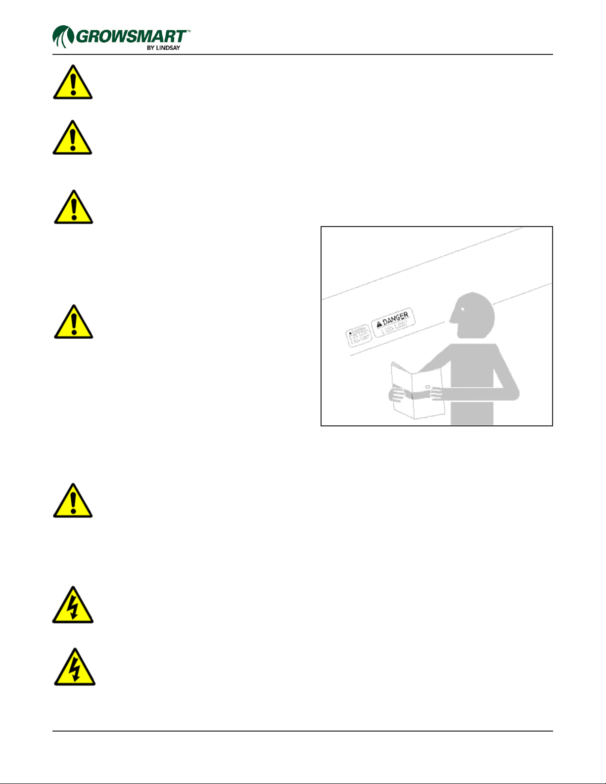
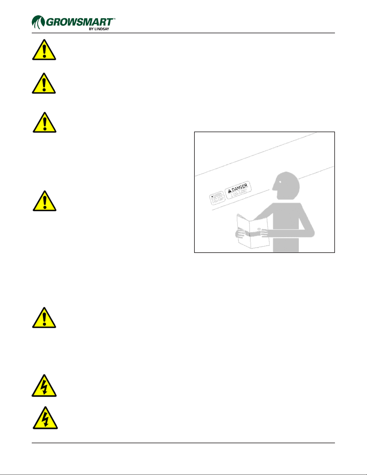
Sécurité individuelle : Vous trouverez tout au long de ce manuel et sur tous les panneaux
de sécurité des avis de mise en garde (« DANGER », « AVERTISSEMENT », « MISE EN GARDE »
et « AVIS »), suivis de la description des risques en question et des actions préventives à mettre en œuvre. Ces
précautions visent à protéger physiquement l'opérateur et toutes les personnes qui se tiennent à proximité de la
machine. Prenez le temps de lire ces précautions.
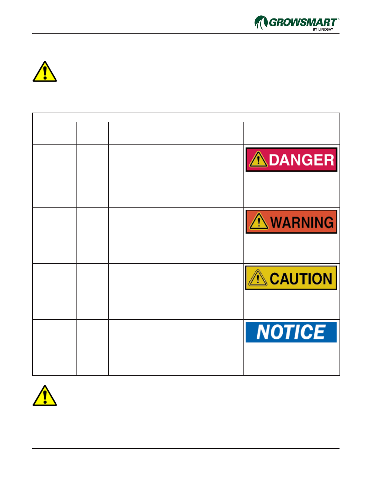
Panneaux de gravité des risques
Couleur
d'arrière-plan
du panneau
Couleur
de
contraste
Signication/Utilisation Illustration des panneaux de
gravité des risques
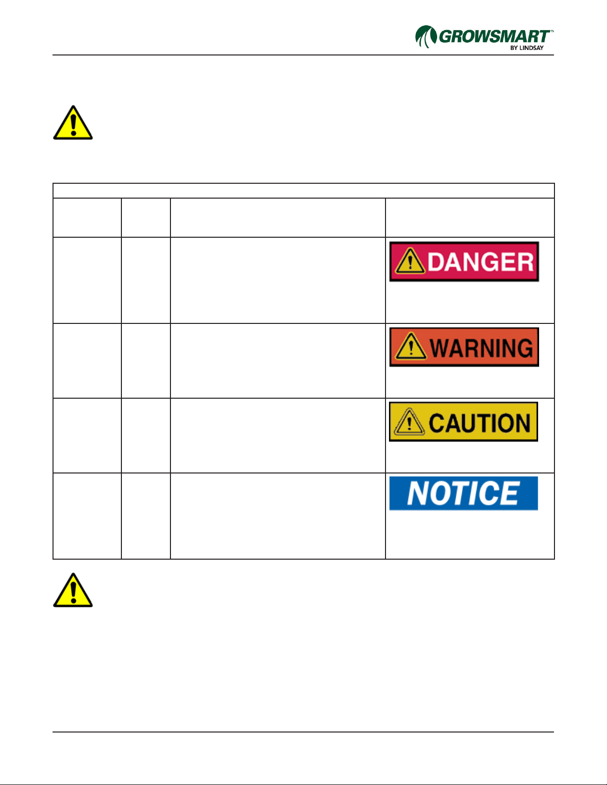
Rouge Blanc Les panneaux de gravité des risques Danger
indiquent un niveau de risque pouvant entraîner
des blessures graves ou mortelles. Le terme
« Danger » est uniquement employé dans
les cas les plus extrêmes. Les panneaux de
danger ne doivent pas être utilisés pour signaler
des risques de dégâts matériels à moins que
ces dangers impliquent aussi des risques de
blessures physiques correspondant à ce niveau.
Orange Noir Les panneaux de gravité des risques
Avertissement indiquent un niveau de risque
modéré qui, s'il est négligé, peut entraîner des
blessures graves ou mortelles. Les panneaux
d'avertissement ne doivent pas être utilisés
pour signaler des risques de dégâts matériels
à moins qu'ils n'impliquent aussi des risques de
blessures physiques correspondant à ce niveau.
Jaune Noir Les panneaux de gravité des risques Mise en
garde indiquent un niveau de risque faible qui,
s'il n'est pas évité, peut entraîner des blessures
mineures ou modérées. Les panneaux de mise
en garde qui ne comportent pas le symbole
d'alerte seront uniquement employés pour
signaler des pratiques peu sûres susceptibles
d'entraîner des dégâts matériels.
Bleu Blanc Les panneaux de gravité Avis sont employés
pour signaler les pratiques qui n'entraînent pas
de blessures corporelles. Le symbole d'alerte
n'est jamais utilisé sur ce type de panneau.
Au lieu du terme « Avis », le terme « Mise en
garde » sans le symbole alerte peut être employé
pour signaler un message qui n'implique pas de
blessures corporelles.
AVERTISSEMENT
Sécurité de la machine : Les avis de mise en garde additionnels (« ATTENTION » et
« IMPORTANT ») portent sur la sécurité de la machine et sont suivis d'instructions spéciques.
ATTENTION : Le terme « ATTENTION » est employé pour avertir l'opérateur d'un risque d'endommagement
potentiel de la machine si une procédure particulière n'est pas respectée.
IMPORTANT : Le terme « IMPORTANT » est employé en vue de communiquer au lecteur les informations
nécessaires pour éviter un endommagement mineur de la machine si une procédure particulière n'est pas respectée.

GS-6 IM3000
Consignes de sécurité
AVERTISSEMENT : Tous les entretiens et opérations de maintenance doivent être effectués
par un concessionnaire Lindsay.
AVERTISSEMENT
Déconnexion de la source d'alimentation : Ne connectez pas la source d'alimentation
au débitmètre tant que toutes les opérations d'installation ne sont pas terminées, que tous les capots n'ont
pas été correctement installés et que tout le personnel ne se tient pas éloigné de l'équipement.
AVERTISSEMENT
Formation : Toutes les personnes appelées à participer à l'installation, à l'utilisation ou à la
maintenance de cet équipement doivent suivre
une formation sur les méthodes à mettre en
œuvre pour mener à bien leurs obligations, au moment de
leur mission initiale et au moins une fois par an ensuite. Il
convient de vérier que ces individus ont bien assimilé cette
formation. Les messages de sécurité et les procédures
appropriées à suivre en cas d'urgence ou dans d'autres
situations doivent être bien compris.
AVERTISSEMENT
Respect des consignes de
sécurité : Lisez attentivement tous les
messages de sécurité présentés dans ce manuel ainsi que
les panneaux de sécurité présents sur le débitmètre. Veillez
à ce que les panneaux de sécurité soient bien lisibles.
Remplacez tout panneau de sécurité manquant ou abîmé.
Apprenez à utiliser la machine et les commandes
correctement. Ne laissez aucune personne utiliser le débitmètre si elle ne dispose pas des instructions
appropriées.
Maintenez le débitmètre en bon état de marche. La machine doit être régulièrement révisée par un technicien
qualié. Toute modication non autorisée peut altérer le fonctionnement et/ou la sécurité du débitmètre, et réduire
sa durée de vie.
MISE EN GARDE
Pratique sûre en matière de maintenance : Veillez à bien comprendre les
procédures de maintenance avant toute intervention.
Déconnectez toujours l'alimentation du débitmètre avant d'effectuer une opération de maintenance.
Maintenez toutes les pièces en bon état. Éliminez les graisses, huiles et débris qui s'accumulent. Assurez-vous
que toutes les pièces ont été correctement installées par un technicien certié.
AVERTISSEMENT
Tension de source appropriée : Assurez-vous que la tension de source correspond à la
tension indiquée sur la plaque signalétique du débitmètre.
AVERTISSEMENT
Connexions électriques : Évitez tout contact de la batterie avec des sources d'étincelles
ou de ammes, car les gaz dégagés par l'électrolyte sont explosifs. Évitez la formation d'étincelles en
connectant le câble de terre en dernier et en le débranchant en premier.

GS-7 IM3000
Consignes de sécurité
AVERTISSEMENT
Inspection du système avant utilisation : Inspectez toujours le débitmètre avant de
l'utiliser. S'il semble endommagé, ne l'utilisez pas et contactez votre concessionnaire Lindsay.
MISE EN GARDE
Éclairage général : Le propriétaire de l'équipement doit fournir l'éclairage général requis.
AVERTISSEMENT
Réparation du débitmètre : Si le débitmètre IM3000 doit être réparé, déconnectez la
source d'alimentation, dépressurisez le système et contactez votre concessionnaire Lindsay.
Seul un concessionnaire Lindsay est habilité à effectuer les réparations nécessaires du système.
Assurez-vous que les pièces du système sont des pièces Lindsay authentiques.
AVERTISSEMENT
Levage de composants : Il convient de faire très attention lorsque vous soulevez des
composants pendant l'installation/l'assemblage. Seul un concessionnaire Lindsay utilisant l'équipement
de levage approprié peut effectuer cette tâche.
Faites attention lorsque vous soulevez des objets lourds. Les composants pesant plus de 22,7 kg (50 livres)
doivent être soulevés avec l'assistance d'un tiers ou d'un appareil de levage mécanique.
AVERTISSEMENT
Protection de sécurité endommagée : N'utilisez pas le système s'il est possible que
la protection soit altérée. Si l'équipement a été modié ou s'il fonctionne de manière anormale, il se
peut que les dispositifs de protection aient été altérés. N'essayez pas d'utiliser l'équipement et faites-le
réparer par un concessionnaire Lindsay.
AVERTISSEMENT : Portez un équipement de protection individuelle (EPI) adéquat
AVERTISSEMENT : Vériez que l'alimentation est coupée/débranchée avant de retirer tout
couvercle de protection.
AVERTISSEMENT : N'utilisez pas ce produit autrement que ce qui est indiqué dans ce manuel.
AVERTISSEMENT
Câbles de données : Utilisez uniquement les câbles de données fournis avec ce débitmètre.
L'utilisation d'un câble non approuvé par Lindsay peut endommager l'équipement et entraîner
l'annulation de la garantie.

GS-8 IM3000
Consignes de sécurité
AVERTISSEMENT
Stockage et transport de la batterie : Les batteries au lithium sont une source
d'énergie importante et peuvent constituer un risque potentiel si elles ne sont pas manipulées
correctement.
Lindsay Manufacturing n'est pas responsable des défaillances des batteries en raison d'une mauvaise utilisation.
Les batteries au lithium ne sont pas corrosives. Cependant, une température extrême (contact avec une amme
ouverte ou court-circuit du système) entraînera la rupture de la batterie ainsi que des blessures graves et des
dommages au niveau de l'équipement. Respectez les précautions suivantes lors de la manipulation ou du
transport des batteries :
• Lors du transport, les étiquettes d'avertissement appropriées doivent être clairement apposées à l'extérieur des
conteneurs.
• Ne transportez pas de batteries ou ne les faites pas fonctionner à des températures qui ne sont pas comprises
dans la plage indiquée.
• N'écrasez pas, ne cassez pas ou ne démontez pas la batterie.
• Ne créez pas de court-circuit, ne rechargez pas, ne surchargez pas ou ne connectez pas la batterie en
inversant la polarité.
• Ne soudez pas au-dessus du boîtier de la batterie ou à proximité immédiate de la batterie.
• N'immergez pas la batterie dans l'eau et n'appliquez aucun liquide sur la batterie.
• Si la batterie est déchargée ou endommagée, consultez Lindsay Manufacturing pour la faire remplacer.
• Respectez toutes les lois et règlementations locales en ce qui concerne la mise au rebut/le recyclage de
batteries au lithium.
MISE EN GARDE
Préparation aux situations d'urgence : Soyez prêt à gérer la moindre urgence.
Portez toujours les équipements de protection personnelle appropriés.
Gardez les numéros de téléphone des médecins, hôpitaux, services d'ambulance et pompiers près de votre
téléphone.

P/N 1605606 Rev A (ECN 32937) 1 IM3000 Installation Manual
IM3000 Irrigation Magnetic Flowmeter
Installation Instructions
Overview
These instructions describe the Growsmart IM3000 Magnetic Flowmeter features as well as provide instructions
for meter installation, specications, user interface explanation and troubleshooting.
The IM3000 comes in these models according to pipe diameter size.
• IM3000-04 for 4” pipe.
• IM3000-06 for 6” pipe.
• IM3000-08 for 8” pipe.
• IM3000-10 for 10” pipe.
• IM3000-12 for 12” pipe.
Features
The Growsmart IM3000 Magnetic Flowmeter provides the following features that set it apart from the competition.
Display with Cover
Converter Housing
Communications Port
(7 Core/Pin) on backside of
housing
Pipe Weldment
Ground Lugs
Flow Direction Indicator
Rubber Liner
Programming Port
(6 Core/Pin) on housing
frontside

P/N 1605606 Rev A (ECN 32937) 2 IM3000 Installation Manual
Transportation
During shipping or transporting of the owmeter, avoid exposing the meter to strong shock or vibrations or impact.
Avoid scratching the rubber liner inside the pipe.
Storage
If possible, store the meter in its unopened packaging until actual installation.
Avoid storing the meter outdoors for an extended period of time. Avoid rain and any direct contact with uids prior
to installation.
Avoid exposing the signal converter to direct sunlight.
Installation
Performance and Operating Specications
The IM3000 is constructed from the following materials:
The pipe consists of epoxy coated carbon steel, with a rubber liner and EPDM constructed O-ring.
The electrodes are made of 316 stainless steel and the electronics housing is constructed from die-cast aluminum
with a powder-coated exterior.
The anges are ANSI 150# which provides a maximum pressure rating of 150 psi.
The IM3000 is rated for operating between 14°F to 131°F (-10°C to 55°C) and should be stored in temperatures
between -40°F to 140°F (-40°C to 60°C).
The IM3000 has the IP68 and NEMA 4x electrical enclosure ratings for environmental protection of the electrical
components.
The IM3000 is available in 4”, 6”, 8”, 10” and 12” pipe sizes. With the following accuracies for their given pressure
ranges. (See the following chart.)
Pipe Size Measurement Range GPM (LPM) Accuracy
Minimum Maximum 0-10% Max Flow 0-100% Max Flow
4” (10.2 cm) 12 (45.4) 1000 (3785) ±2% ±1%
6” (15.2 cm) 30 (113.6) 2500 (9463) ±2% ±1%
8” (20.3 cm) 50 (189.3) 4480 (16,958) ±2% ±1%
10” (25.4 cm) 80 (302.8) 7010 (26,535) ±2% ±1%
12” (30.5 cm) 115 (435.3) 10,090 (38,195) ±2% ±1%
IM3000 owmeters are equipped with conductivity-based empty pipe warning functionality.
All IM3000 are factory calibrated and require no eld calibration.

P/N 1605606 Rev A (ECN 32937) 3 IM3000 Installation Manual
Meter Positioning
It is important to install owmeters so the readings are always accurate. The meters are designed to give a zero
reading should one or more electrodes become exposed. Air bubbles and sediment in the pipe can cause false
readings.
For the best performance, install the owmeter in pipeline locations where the pipe will be full when there is ow.
Also, rotating the pipe 45° (or one ange hole position) will offset the electrodes enough to avoid air bubble and
sediment locations that typically occur over center within the pipe. The following diagram shows proper and im-
proper installation options.
Air bubbles can
pass over electrode
Sediment can build up
on this electrode
Problematic Sensor Orientation Recommended Sensor Orientation
Turned 45° the
electrodes remain
submerged
Turned 45° the
electrodes are
above sediment
buildup level
Problematic Meter Positioning
Recommended Meter Positioning
Air can be trapped,
loss of accuracy
Allows air to bleed off,
higher accuracy
Vertical downow,
open discharge
Vertical upow
with full pipe

P/N 1605606 Rev A (ECN 32937) 4 IM3000 Installation Manual
The following diagram shows proper straight pipe installation recommendations.
WARNING: Electrical Shock
When installing IM3000 owmeters to a plastic pipeline, or when externally powered, it is very impor-
tant to ground the meter to avoid electrical shock hazard. Failure to do so can result in electrocution.
Inlet and Outlet Distances
Elbow Distance
Pump Distance
10x Pipe Dia. 3x Pipe Dia.
Turbulence from pump actuation can cause drops and spikes in reading if meters are install too close to the pump
outlet. Meters should be installed downstream from the pump discharge and never at the pump inlet. The mini-
mum straight pipe length for downstream installation must be 10 times the pipe diameter at the meter inlet and
three times the pipe diameter at the meter outlet.
In chemigation applications, the IM3000 owmeter must be placed either upstream from the chemical injection line
or far enough downstream (typical pump distance) that complete mixing occurs before the solution reaches the
meter. Proper placement will prevent spikes and drops in readings that result when uids with varying conductivity
pass through the meter.
The measured uid must have a minimum 20µ Siemens/cm conductivity.
2x Pipe Dia. 1x Pipe Dia.
Minimum length of straight pipe at the meter inlet must be two times the pipe diameter and one times the pipe
diameter at the meter outlet. Expansion joints can be installed in the pipeline after the meter.
2x Pipe Dia. 1x Pipe Dia.
Elbows should not be placed closer than two times the pipe diameter to the meter inlet and one times the pipe
diameter to the meter outlet.

P/N 1605606 Rev A (ECN 32937) 5 IM3000 Installation Manual
Flow Meter Dimensions
The following dimensions and weights are provided for pipeline design and installation.
Meter Weights
Meter Model Lindsay P/N Weight in lbs. (kg)
IM3000-04 1608505 44 (20)
IM3000-06 1605551 60 (27)
IM3000-08 1605548 97 (44)
IM3000-10 1605549 130 (59)
IM3000-12 1605550 185 (84)
Meter Dimensions
Dimensions are in Inch (mm).
Nom. ØH H1 L ØD D1 t1 BC
4 (100) 14.30 (363) 9.80 (249) 10.24 (260) 3.15 (80) 9.00 (227) 0.94 (24) 7.50 (191)
6 (150) 16.00 (406) 10.50 (267) 12.28 (312) 5.12 (130) 11.00 (279) 1.00 (25) 9.50 (241)
8 (200) 18.00 (455) 11.20 (284) 14.25 (362) 6.46 (164) 13.50 (343) 1.13 (29) 11.75 (299)
10 (250) 20.30 (515) 12.30 (312) 18.19 (462) 8.58 (218) 16.00 (406) 1.19 (30) 14.25 (362)
12 (300) 22.70 (576) 13.20 (335) 20.16 (512) 10.31 (262) 19.00 (483) 1.25 (32) 17.00 (432)
Nom. ØD2 # of Holes
4 (100) 0.75 (19) 8
6 (150) 0.88 (22) 8
8 (200) 0.88 (22) 8
10 (250) 1.00 (25) 12
12 (300) 1.00 (25) 12
H
1
H
D
1
t
1
D
2
B
C
ØD

P/N 1605606 Rev A (ECN 32937) 6 IM3000 Installation Manual
Grounding
When grounding on metal pipe, the electric potential of the uid, meter and surrounding pipe must be equalized.
This is done by connecting the ground wires on the owmeter body to one of the lug locations on the mating
ange connection.
NOTE: Make sure the ground wire or lug is between the ange bolt head (or nut) and the outside surface of the
mating pipe ange. This grounding must be completely isolated from the owmeter. (See the following diagram.)
With plastic pipe, a grounding rod or other ground-to-earth connection must be installed.
Flowmeter grounding
screw and wire
Ground lug is connected
to the pipe ange, on the
outside, to keep grounding
isolated from the owmeter.
Flowmeter grounding screw and
wire
Earthen ground rod

P/N 1605606 Rev A (ECN 32937) 7 IM3000 Installation Manual
Wiring IM3000 Power / Output Cable
Wire Color Core # Function
White 1 Communications Ground
Blue 2 M_RXD
Orange 3 M_TXD
Purple 4 Pulse Output (-)
Brown 5 Pulse Output (+)
Pink 6 External Power (+)
Black 7 External Power (-)
Wiring BOSS to the IM3000
Pink (+) Supply to TB 3.5
Black (-) Supply to TB 3.4
Purple (-) Pulse to TB 3.4
Brown (+) Pulse to TB 3.2
Resistor to TB3.2 and TB3.5
Bare drain wire can be connected to panel ground.
To communications
port at rear or the
meter.
White
Blue
Purple
Orange
Brown
Pink
Black
IM3000 K-Factors
Pipe Size Raw K-Factor BOSS K-Factor
4” 12,000 12
6” 6,000 6
8” 3,000 3
10” 2,000 2
12” 1,500 1.5

P/N 1605606 Rev A (ECN 32937) 8 IM3000 Installation Manual
Wiring VISION to the IM3000
Pink (+) Supply to TB 4.2
Black (-) Supply to TB 4.1
Purple (-) Pulse to TB 4.1
Brown (+) Pulse to TB 4.3
Resistor to TB 4.2 and 4.5
Bare drain wire can be connected to panel ground.
IM3000 K-Factors
Pipe Size Raw K-Factor VISION K-Factor
4” 12,000 12
6” 6,000 6
8” 3,000 3
10” 2,000 2
12” 1,500 1.5

P/N 1605606 Rev A (ECN 32937) 9 IM3000 Installation Manual
Vibrations
Vibrations in the system pipeline can damage the
owmeter and should be negated. The meter meets
IEC 68-2-64 standards for shock resistance. However,
if there is signicant vibration in the pipeline, support
brackets can be installed on both sides of the meter to
help eliminate vibration.
Power Supply
The IM3000 owmeter can be powered externally or by
battery power.
An external power source that provides 8 to 32 VDC at
30mA can be used. When installed, the battery pack
can be used as a backup power source.
A battery pack consisted of 4 lithium 3.6V 19Ah “D”
sized batteries with an estimated 3 to 5 years of life. An
external expansion battery pack can be used to double
battery life. This expansion pack consists of 4 additional
3.6V “D” sized lithium batteries that link to the meter
body via IP68 cable connection and secured onto the
meter.
An indicator on the meter will show a battery symbol
with bars representing the power level of the batteries.
When the battery power is depleted, the battery symbol
will show no power level bars (empty) and a “Low Bat”
warning will display.
Battery Pack Replacement
1. Replace the by removing the socket-head cap
screws, using a 5mm Allen Wrench. Retain the
screws and washer for re-assembly.
2. Remove the phillips-head screws from the face
plate. Retain the screws for re-assembly.
3. Lift the Display/PCB unit from the meter housing.
4. Disconnect the cable harness from the PCB unit.
5. Remove the copper standoff fasteners from the
aluminum shield.

P/N 1605606 Rev A (ECN 32937) 10 IM3000 Installation Manual
6. Remove the aluminum shield and the silicone gasket
underneath which hold the battery pack in place.
7. Route the signal and excitation cable harnesses
through the center of the battery pack and remove
the battery pack from the meter housing.
8. Take the new battery pack and route the signal and
excitation cable harnesses through the center of the
battery pack. Place the battery pack into the meter
housing.
9. Ensure no cable harnesses are caught between the
bottom of the battery pack and the meter housing.
10. Re-install the silicone gasket, aluminum shield and
copper standoffs.
Table of contents
Popular Measuring Instrument manuals by other brands

LINSHANG
LINSHANG LS162 user manual

Hanna Instruments
Hanna Instruments HI 719 quick start guide

Elko
Elko iNELS Air AirIM-100S/M operating instructions

Feig Electronic
Feig Electronic ID ISC.ANT1710/690 Crystal Gate Excellence... Quick installation

Seneca
Seneca Z203-1 quick start guide

Fluke Calibration
Fluke Calibration 1586A Super-DAQ Application note