Innovative Control Systems Auto Sentry Petro User manual

Auto Sentry® Petro
Installation Guide - Version 3.7

Information in this manual is subject to change without notice. The example
companies, organizations, products, domain names, email addresses logos,
people, places and events depicted herein are fictitious. No association with any
real company, organization, product, domain name, email address, logo, person,
place or event is intended or should be inferred unless otherwise noted. No part
of this manual may be reproduced or transmitted in any form or by any means,
electronic or mechanical, for any purpose without the express written
permission of Innovative Control Systems, Inc. (ICS)
ICS and its product trademarks in this manual are trademarks of Innovative
Control Systems. All other marks are property of their respective owners.
© 2018 Innovative Control Systems, Inc. All rights reserved.
Innovative Control Systems, Inc.
1349 Jacobsburg Road
Wind Gap, PA 18091
(610) 881-8100

Auto Sentry® Petro - Installation Guide 3 Contents
Contents
Chapter 1: Site Layout 5
Location - - - - - - - - - - - - - - - - - - - - - - - - - - - - - - - - 5
Auto Sentry® Petro Power Requirements - - - - - - - - - - - - - - - - - 5
Auto Sentry® Petro Wiring Guidelines - - - - - - - - - - - - - - - - - - 5
Conduit Wiring Guidelines - - - - - - - - - - - - - - - - - - - - - - - - 6
Equipment Dimensions, Measurements, and Ratings- - - - - - - - - - - - 6
Grounding - - - - - - - - - - - - - - - - - - - - - - - - - - - - - - - 7
Recommended and Accepted Grounding Methods - - - - - - 7
Wire Gauge and Conduit Size - - - - - - - - - - - - - - - - - - - - - - 8
Auto Sentry® Petro Layout - - - - - - - - - - - - - - - - - - - - - - - 9
Auto Sentry® Petro Placement Front and Side View- - - - - - - - - - - - 10
Auto Sentry® Petro Dimensions - - - - - - - - - - - - - - - - - - - - - 11
Auto Sentry® Petro Base Placement without Riser - - - - - - - - - - - - 11
Auto Sentry® Petro Base Placement with Riser - - - - - - - - - - - - - - 12
Chapter 2: Molded Plastic Installation 13
Attaching the Auto Sentry® Petro to the J Bolts - - - - - - - - - - - - - 13
Hardware for Roto Molded Plastic Installation- - - - - - - - - - - - - - - 14
Hardware if installing the Plastic Door Panels only: - - - - - 14
Hardware: - - - - - - - - - - - - - - - - - - - - - - - - 14
Front and Back Door Roto Molded Plastic Installation - - - - - - - - - - - 16
Roto Molded Plastics for the Petro Installation - - - - - - - - - - - - - - 19
Chapter 3: System Wiring 27
Warning Symbol - - - - - - - - - - - - - - - - - - - - - - - - - - - - - 27
AC Power Terminations - - - - - - - - - - - - - - - - - - - - - - - - - 28
Auto Sentry® Petro AC Power Terminations - - - - - - - - - - - - - - - 29
Power Wiring Layout - - - - - - - - - - - - - - - - - - - - - - - - - - 30
Alternative Wiring Option - - - - - - - - - - - - - - - - - - - - - - - - 31
Power Wire Schedule - - - - - - - - - - - - - - - - - - - - - - - - - - 32
ICS Power Distribution Box- - - - - - - - - - - - - - - - - - - - - - - - 33

Auto Sentry® Petro - Installation Guide 4 Contents
Control Box Terminations - - - - - - - - - - - - - - - - - - - - - - - - 34
In-Bay Controller Wire Terminations - - - - - - - - - - - - - - - - - - - 35
In-Bay Wiring Layouts - - - - - - - - - - - - - - - - - - - - - - - - - - 36
Single In-Bay without a Server Wiring Layout - - - - - - - - - - - - - - - 36
Chapter 4: Communications Wiring 37
Installation Requirements - - - - - - - - - - - - - - - - - - - - - - - - 37
System Network Cables - - - - - - - - - - - - - - - - - - - - - - - - - 38
Chapter 5: Parts Identification 39
Exterior Components (Front View) - - - - - - - - - - - - - - - - - - - - 39
Interior Front Door Components - - - - - - - - - - - - - - - - - - - - - 40
Interior back left-side of Auto Sentry® Petro - - - - - - - - - - - - - - - 42
Interior Rear Door Components - - - - - - - - - - - - - - - - - - - - - 43
Interior back right-side (Moneris Credit Solution) - - - - - - - - - - - - - 44
Interior back right-side (TXP Credit solution) - - - - - - - - - - - - - - - 45
Roto Molded Auto Sentry® Petro Parts - - - - - - - - - - - - - - - - - - 46
Document Change History - - - - - - - - - - - - - - - - - - - - - - - - 47

Auto Sentry® Petro - Installation Guide 5 Site Layout
CHAPTER 1: Site Layout
Careful planning for the layout of the site will help eliminate possible problems with the startup of
your system. This document is intended to provide instructions to properly install the Auto
Sentry® Petro to ensure continued, reliable system operation.
All site wiring must be performed by a licensed electrician that must comply with all local and
national codes.
Permanent connections to be installed and used in accordance with building/fire codes.
Location
The Auto Sentry® Petro has been designed to operate in an outdoor environment.
The unit itself contains two hinged-panel doors, one on the front and one on the back of the
unit. The Auto Sentry® Petro must be located with enough clearance for the doors to open
easily without obstructions.
The unit must be located so that conduit connections can be easily made and the internal
components can be accessed.
Auto Sentry® Petro Power Requirements
Electrician must provide one 15 Amps @ 120 VAC dedicated circuit to power the unit.
The unit must be properly grounded. See “Grounding” on page 7 for more information.
Auto Sentry® Petro Wiring Guidelines
Run conduit and wires up through the center of the stainless-steel base into the unit.
For an existing site, use a hole saw to drill new conduit holes through stainless steel base if
necessary. File and tape edges of new holes before affixing conduit.
Use wiring ties and wire clamps inside unit to contain wires.
All conduit runs should meet local and national codes. Conduits shall be properly connected
and securely fastened to the boxes with listed conduit hubs, and should be tightened to the
torque specs of the manufacturer.

Auto Sentry® Petro - Installation Guide 6 Site Layout
Conduit Wiring Guidelines
All conduit must be rigid PVC or metal.
High-voltage (AC) and low-voltage (DC) must not be combined in a common conduit, junction
box, or wire trough.
Equipment Dimensions, Measurements, and Ratings
When mounting the unit, minimum clearances must meet local recommended standards.
Table 1: Dimensions, Measurements and Ratings
Dimension Amount Notes
Width 32 1/2” —
Height 55 1/2'' —
Depth 17'' Includes heat exchanger cover panel.
Weight 250 lbs. —
Operating
Temperature Range
-20 °F to 120 °F
-29 °C to 48 °C
—
Frequency 50/60 Hz —
Supply Voltage 110 VAC
230 VAC
Intended for permanently connected supply.
Max. Amps. 10 Amps @ 120 VAC
6 Amps @ 240 VAC
—
IPX Rating NEMA 4X Enclosures constructed for either indoor or outdoor use to
provide a degree of protection to personnel against inci-
dental contact with the enclosed equipment; to provide a
degree of protection against falling dirt, rain, sleet, snow,
windblown dust, splashing water, and hose-directed water
from water jets at any direction; and that will be undam-
aged by the external formation of ice on the enclosure.
Including protection against corrosion.

Auto Sentry® Petro - Installation Guide 7 Site Layout
Grounding
The Auto Sentry® Petro and peripheral equipment must be properly grounded.
Recommended and Accepted Grounding Methods
Proper system grounding is an extremely important part of the system installation. Grounds for all
system devices should be wired to the breaker panel ground bus bar which, in turn, should be
grounded to a ground rod. A conduit ground does not provide a sufficient ground. It is
recommended that the neutral and ground bus bars be bonded together when it is not
prohibited by local codes.
The universal ground symbol identifies the grounding terminal located in the upper-left chamber,
bottom left side near terminal blocks. A second ground is marked and located in the base,
bottom-left side.
This is the dedicated 120 V/240 V line for the heat exchanger.
IMPORTANT: Improper grounding will void equipment warranty.
!
WARNING: Ground wire must be connected to the
ground lug. Failure to properly ground
the unit could result in unit failure and/or
bodily injury.

Auto Sentry® Petro - Installation Guide 8 Site Layout
Wire Gauge and Conduit Size
When planning the orientation of the wiring runs, follow the applicable ICS wiring diagrams and
consider the layout of the components at the site.
To determine conduit size needed, see the Table2, “Max. Number of Wires (THHN) in a Given
Conduit Size”.
Table 2: Max. Number of Wires (THHN) in a Given Conduit Size
½ ¾ 11 ¼ 1½ 22 ½ 3
AWG 14 13 24 39 69 94 154 — —
AWG 12 10 18 29 51 70 114 164 —
AWG 10 611 18 32 44 73 104 160
AWG 8 35916 22 36 51 79
AWG 6 12611 15 26 37 57
AWG 4 1147916 22 35
AWG 3 1136813 19 29
AWG 2 1135711 16 25
AWG 1 11135812 18
Auto Sentry® Petro - Installation Guide 9 Site Layout
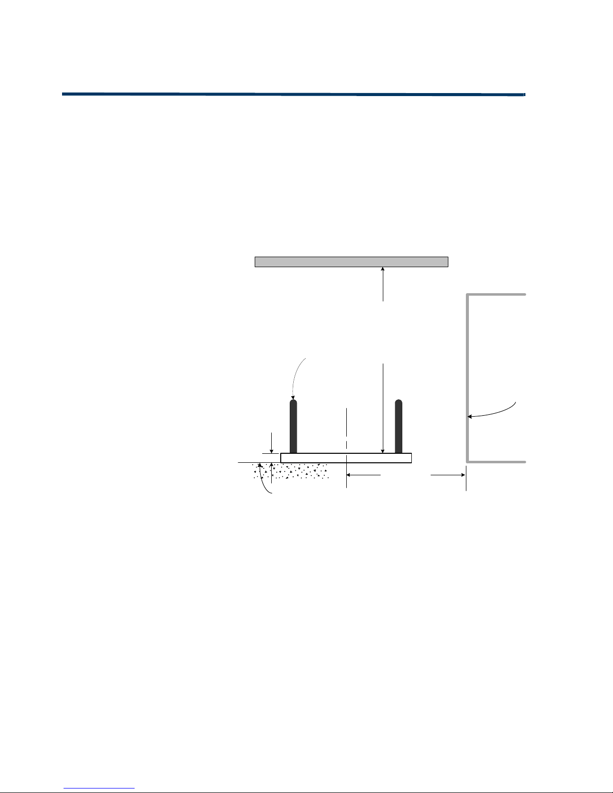
Auto Sentry® Petro Layout
Figure 1. Auto Sentry® Petro Layout
6"
FINISHED TRAFFIC GRADE
LINE
Auto SentryPetro
RAISED CURB
BOLLARD
SEE NOTE
Minimally12 Feet
AUTO SENTRY® PETRO
IN-BAY LAYOUT
*** THIS DRAWING IS ONLY INTENDED TO SHOW THE GENERAL LAYOUT AND DIMENSIONS
NECESSARY FOR THE PROPER PLACEMENT OF THE AUTO SENTRY PETRO. ANY DEVIATION
MAY CAUSE DAMAGE TO THE AUTO SENTRY PETRO. ***
THE HEIGHT FROM THE BOTTOM OF THE AUTO
SENTRY TO THE BOTTOM OF ANY CANOPY WILL
BE DETERMINED BY THE CAR WASH, BUT
SHOULD BE ONLY SLIGHTLY GREATER THAN THE
MAXIMUM ALLOWABLE HEIGHT FOR ANY
VEHICLE TO ENTER THE IN-BAY .
CANOPY ABOVE AUTO SENTRY PETRO
NOTE: ICS DOES NOT RECOMMEND AN IDEAL DISTANCE BETWEEN THE
AUTO SENTRY PETRO AND THE ENTRANCE TO THE IN-BAY TUNNEL, BUT
DOES OFFER THE FOLLOWING INFORMATION TO THE IN-BAY OWNER FOR
THEM TO DECIDE WHAT THE APPROPRIATE DISTANCE SHOULD BE FOR
THEIR SITE:
1. THE TYPE OF IN-BAY AUTOMATIC: EACH IN-BAY AUTOMATIC IS
DIFFERENT AND THEY ALL EXPEL DIFFERENT AMOUNTS OF BOTH WATER
AND CHEMICALS, WHICH IF BLOWN ONTO THE AUTO SENTRY PETRO IN
ANY GREAT AMOUNT COULD IMPEDE THE USERS ABILITY TO SEE AND/OR
PROPERLY UTILIZE THE TOUCH SCREEN.
2. THE RELATIVE WIND DIRECTION: IF THE PREVAILING WIND BLOWS
FROM THE AUTO SENTRY PETRO TO THE BAY ENTRANCE, THEN THERE
SHOULD BE ONLY MINOR PROBLEMS FROM BLOW-BACK. IF THE
PREVAILING WIND BLOWS THROUGH THE BAY TOWARDS THE AUTO
SENTRY PETRO THEN THE AUTO SENTRY PETRO WILL BE GREATLY
AFFECTED. IF THE PREVAILING WIND IS PERPENDICULAR TO THE TUNNEL
THERE WILL AGAIN BE MINOR PROBLEMS.
3. DRYER TYPE: THE TYPE OF DRYER USED IN THE WASH WILL ALSO BE A
FACTOR. DRYERS THAT SIMPLY BLOW DOWN THE TUNNEL TOWARDS
THE AUTO SENTRY PETRO WILL FACILITATE THE BUILDUP OF WATER AND
CHEMICALS ON THE AUTO SENTRY PETRO EVEN ON WINDLESS DAYS.
4. BAY DOORS: IF BAY DOORS ARE INSTALLED AND CLOSE BETWEEN
VEHICLES, THEN THERE SHOULD NOT BE ANY PROBLEMS AT ALL AND THE
AUTO SENTRY PETRO CAN BE PLACED AS CLOSE TO THE ENTRANCE AS
POSSIBLE WHILE ALLOWING A SECOND VEHICLE TO PULL UP TO THE
AUTO SENTRY PETRO WITH ENOUGH ROOM FOR THE CUSTOMER TO
OPERATE IT WHILE THE FIRST CAR IS IN THE TUNNEL (MINIMALLY THIS
DISTANCE IS TWELVE FEET FROM THE CENTER OF THE AUTO SENTRY
PETRO TO THE NEAREST OBSTRUCTION).
ALL OF THE ABOVE FACTORS MUST BE TAKEN INTO CONSIDERATION
WHEN DETERMINING THE BEST LOCATION FOR THE AUTO SENTRY PETRO
IN RELATION TO THE ENTRANCE OF THE WASH BAY. AS A GENERAL RULE,
THE FURTHER AWAY THE AUTO SENTRY PETRO IS FROM THE BAY
ENTRANCE, THE BETTER OFF IT WILL BE.
FACE OF BUILDING
THIS DRAWING IS NOT TO SCALE.
Auto Sentry® Petro - Installation Guide 10 Site Layout
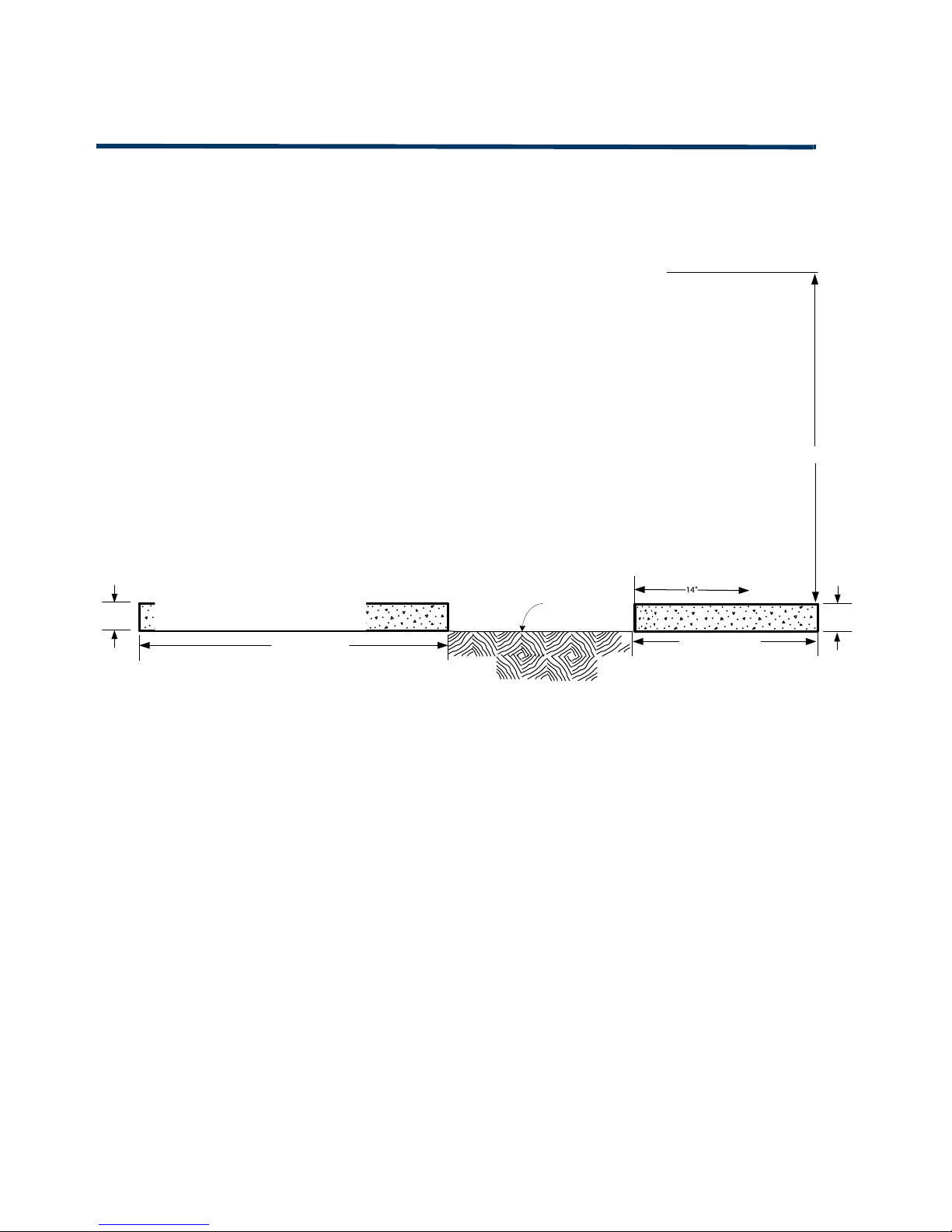
Auto Sentry® Petro Placement Front and Side View
Figure 2. Auto Sentry® Petro Placement - Front and Side View
MINIMUM 42"
6"
FINAL
TRAFFIC
GRADE
LINE
MINIMUM 42"
6"
• The face of the Auto Sentry Petro is to be in
line with the front edge of the curbing.
• The rear wall of the Auto Sentry Petro
should be set at 14" fromthe front edge of
the curbing.
• Curb Height should be 6".
• The curbing should have bollards at both
ends to protect the Auto Sentry Petro.
• If a curb is not poured, a 6" riser can be
purchased and installed on the grade. The
base of the Auto Sentry Petro will then be
mounted on to the riser.
Auto Sentry Petro
Placement
55 ½”
Front
Back
Auto Sentry® Petro - Installation Guide 11 Site Layout
Auto Sentry® Petro Dimensions
Figure 3. Auto Sentry® Petro Dimensions
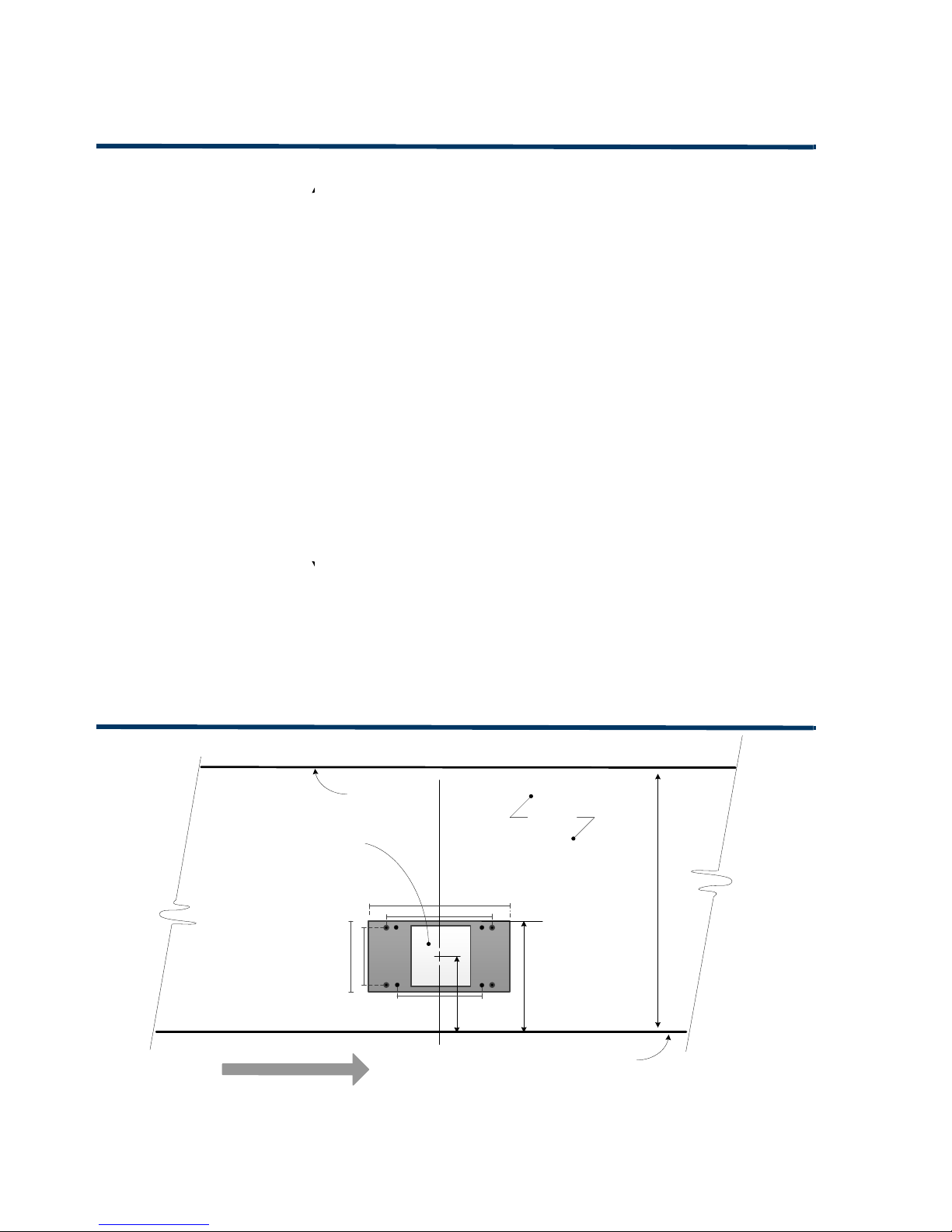
Auto Sentry® Petro Base Placement without Riser
Figure 4. Auto Sentry® Petro Base Placement without Riser
ϯϭЪ
ϭϱЪ
ϴΗ
ϱϱЪ
ϭϲΗ
ϱϱЪ
ϮΗ
^ŝĚĞsŝĞǁ &ƌŽŶƚsŝĞǁ
14"
5"
BACK
EDGE OF
CURB
FRONT EDGE
OF CURB
4' - 0"
14"
CONCRETE
ISLAND
OPEN SPACE IN BASE OF AUTO
SENTRY FOR PLACEMENT OF
CONDUITS
6.06" x 6.06"
VEHICLE TRAVEL
DIRECTION OF
BASE PLACEMENT TOP VIEW
10"
C
L
OF PETRO
8"
16"
8"
Auto Sentry® Petro - Installation Guide 12 Site Layout
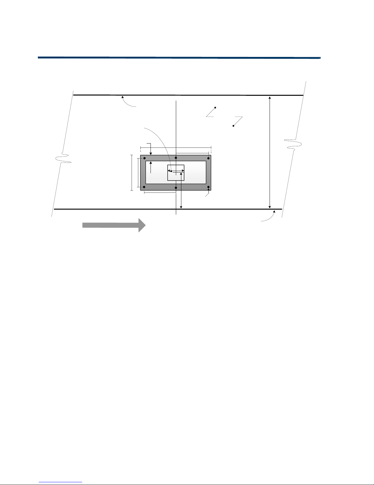
Auto Sentry® Petro Base Placement with Riser
Figure 5. Auto Sentry® Petro Base Placement with Riser
11- 9/16"
BACK
EDGE OF
CURB
FRONT EDGE
OF CURB
4' - 0"
CONCRETE
ISLAND
OPEN SPACE IN BASE OF RISER
FOR PLACEMENT OF CONDUITS
IN THE AUTO SENTRY PETRO
6- ½” x 6- ½”
VEHICLE TRAVEL
DIRECTION OF
AUTO SENTRY PETRO
BASE PLACEMENT WITH RISER - TOP VIEW
10"
C
L
OF PETRO
9"
24- ¼”
13- 9/16"
9"
6x 9/16"
6- ½”
4x 2"

Auto Sentry® Petro - User Manual 13 Molded Plastic Installation
CHAPTER 2: Molded Plastic Installation
The Auto Sentry® Petro is designed to be rugged from the inside out. The heart of this design is a
solid stainless steel metal cabinet with full air conditioning. The durable roto molded plastic
surrounds and protects the metal cabinet core and gives the Auto Sentry® Petro a fresh new style.
Brand vinyl with your logo and graphics to make the Auto Sentry® Petro your own.
After the J bolts have been set in the concrete according to your site plan, the installation of your
Auto Sentry® Petro can begin.
Attaching the Auto Sentry® Petro to the J Bolts
If your site does not have a raised curb, contact ICS to order a riser to place your Auto Sentry®
Petro upon. The riser gives the Auto Sentry® Petro the proper height that is necessary to deliver to
your customers, who are inside their vehicles, the most ergonomic, easy to reach experience at
the Auto Sentry® Petro payment terminal.
1Set J bolts in concrete according to your site’s layout.
NOTE: If installing the Auto Sentry Petro in the concrete curbing, the first four J bolts are
standard, see Figure6. If available, the extra four J bolts simply provide added security
but are not necessary. If installing a riser, see Figure5.
Items Needed: nuts and washers (site provided) for the 3/8” J bolts to attach the base.
Figure 6. J bolts in base of Auto Sentry® Petro without a riser
2Run the power cable and two Cat 6 cables (the 2nd Cat 6 is for EMV only) to the Auto Sentry®
Petro and pull up them up through the center of the Auto Sentry® Petro’s pedestal.
3As you line up the J bolts to the holes in the base of the Auto Sentry® Petro, place the Auto
Sentry® Petro on top of the concrete.
4Tighten (4) or (8) nuts and (4) or (8) washers to the J bolts.
NOTE: If you are attaching 4 J bolts in your concrete, attach #1-4 in Figure6. If you have 8 J bolts
in your concrete, then attach #1-8 in Figure6. Using 8 bolts is optional.

Auto Sentry® Petro - User Manual 14 Molded Plastic Installation
Hardware for Roto Molded Plastic Installation
Hardware if installing the Plastic Door Panels only:
Depending on the shipment method, the Auto Sentry Petro may arrive without the plastics
installed on the doors. The following hardware bags are ONLY necessary if installing the front and
back door plastic roto molded panels on the metal doors of the Petro. If the doors are metal and
need the plastic covers installed, then the following hardware bags will be included:
Bag M (1) #6 x 3/8” and Bag K (19) # Keps
Bag N (20) Rubber Washer
Hardware:
After the Auto Sentry® Petro is secured to the concrete with the J bolts, the next step is to attach
the five Roto Molded Plastic pieces to the metal core of the Petro. The following hardware is
needed for the Roto Molded Plastic installation:
Bag A (6) 1/4” × 20 × 1- 1/2” cap screws and Bag H(6) 1/4" washers
Bag B (4) 1/4” × 20 × 1- 1/2” oval screws
Bag C (3) #10 x 1-1/2” screws with (3) #8 washers
Bag D (21) #8 × 11 x 1- 1/4” screws (no washers)
Bag E (8) 1/4” × 20 × 3/8” bolts
Bag F (4) #10 × 32 × 1/2" machine screws (no washers)
Bag J(8) #10 × 32 × 1” Screws (no washers)

Auto Sentry® Petro - User Manual 15 Molded Plastic Installation
Figure 7. Roto Molded Plastic Pieces
There are two small Roto Molded gray plastic pieces #1 and #2 that fit together to cover the base of the
metal pedestal.
#ICS Part Number
1Base Front
2Base Back
3Gray Cover
4Front Blue Cover
5Back Blue Cover
#1
#2
#3
#4 #5

Auto Sentry® Petro - User Manual 16 Molded Plastic Installation
After the Auto Sentry Petro is placed on the riser or J-bolts, and attached securely, you can follow
the installation of the plastic pieces if your unit does not have the plastics on the front and back
doors. If it does have plastic covering the metal doors, then skip to the next section.
Front and Back Door Roto Molded Plastic Installation
1Locate the Rear Roto Plastic Mold and lay on flat surface.
2Lay a rubber washer on each of the 10 bosses on the rear plastic mold. See Bag N.
See Figure8and Figure9.
Figure 8. Interior of Roto Plastic Mold for the Rear Door
Figure 9. Rubber Washer on Boss

Auto Sentry® Petro - User Manual 17 Molded Plastic Installation
3After all the rubber washers are in place, line up the (10) screws in the bosses in the rear door
roto mold with the exterior of the rear door of the Auto Sentry Petro.
Figure 10. Interior of Rear Door (10) Screw Holes
4Using a standard 5/16”nut driver, snuggly tighten (10) keps nuts to (10) screws on the inside of
the Auto Sentry Petro door. See Figure10 and Figure11. See Bag K.
C
A
U
T
I
O
N
:
D
O
NOT OVER TIGHTEN. Two pound-foot torque is recommended.
Over torquing could cause shearing or cracking.
Figure 11. Keps Nut

Auto Sentry® Petro - User Manual 18 Molded Plastic Installation
5Locate the Roto Plastic Molded Front Door Cover, and place the remaining (9) rubber washers
on the bosses. See Figure12. See Bag N.
6Line up the (9) screw holes, and place the roto plastic mold on the door.
Figure 12. Roto Molded Plastic Front Door Cover
7Using a standard 5/16”nut driver, snuggly tighten (9) keps nuts to (9) screws on the inside of
the Auto Sentry Petro door. See Figure11.
CAUTION: DO NOT OVER TIGHTEN. Two pound-foot torque is recommended. Over torquing
could cause shearing or cracking.
8Uncover the screw hole on the left side of the interior Auto Sentry Petro front door. This hole is
for the only boss that has a glued on rubber washer and no screw inside it. Insert (1) #6 x 3/8”
screw in this hole and snugly tighten. See Figure13. See bag M.
Figure 13. L: Hole for Screw R: Boss that comes with a glued on rubber washer

Auto Sentry® Petro - User Manual 19 Molded Plastic Installation
Roto Molded Plastics for the Petro Installation
Stop! If your roto molded plastic door panels are not screwed on the Petro metal doors, then go
back to step #1 in the previous section.
Figure 14. (6) holes in metal base line up with plastic covers
Figure 15. Base Roto Molded Gray Plastics
Begin here if your roto molded plastic doors are securely fastened on the Petro metal doors.
1Place roto-mold #2 on the rear of the base and start Insert (2) 1/4” 20 x 1- 1/2” cap screws with
1/4” flat washers. (Bag A / Bag H) See Figure15.
2Place roto-mold #1 on the front of the base and start remaining (4) screws and washers
(Bag A / Bag H). See Figure15.
3Line up the holes in the roto molded plastic cover pieces with the holes in the metal base.
This is a 4.5 hex key. See Figure14.
4Use a ratchet hand tool and attach roto mold #1 and #2 with (6) 1/4” x 20 x 1- 1/2”: Cap Screws
and washers (Bag A / Bag H) to a lightly snug fit.
CAUTION: DO NOT OVER TIGHTEN. Two pound-foot torque is recommended. Over torquing
could cause shearing or cracking.

Auto Sentry® Petro - User Manual 20 Molded Plastic Installation
5Locate the gray full-size Auto Sentry® Petro roto mold #3. See Figure16.
Figure 16. Roto Mold Plastic #3 (Front view)
6On the Auto Sentry® Petro, open the front door to perform the next step.
7Remove the plastic keeper on the sonic sensor.
8Place the Roto Molded Plastic #3 over the Auto Sentry® Petro metal core.
Table of contents


