Specifications are subject to change without notice. No liability accepted for errors or omissions.
7
STANDARD MODEL TABLE
OPTIONS
Temperature
compensation for
charging
Alarms - SR500D..
- SR500L..
Alarm contacts
DC Input
Earth fault alarm
(external to PSU))
Temperature sensor on 1.7m lead with
adhesive pad: -4mV / °C / cell ±10%
Order Code: +TEMPCO
Mains fail (or PSU in standby mode)
DC low (Battery low or PSU low)
- Charger: set at 1.83V/cell
- PSU: set at 83% V out
• As SR500D.. + DC high alarm (NB: no
alarm relay fitted on HV versions, only
LED indication)
C - NO - NC changeover rated 1A /50V DC,
32VAC
110VDC ( -150) or 220VDC (180-270)
Please note that an external fuse or MCB
must be fitted on the output for short circuit
protection.
Detects leakage to earth of DC output and
provides relay output
Code: +ALARM/EFDM (20-60V)
+ALARM/EFDH (61-150V)
* Please specify on ordering that
unit is to be used for float charging
(except for 12V model which is set
at 13.8V by default).
OPTIONS
Communications Port
Internal V/I meter
Mounting option :
19”rack mount
Wall mount enclosure
Choice of RS485, RS232, ethernet (SNMP or
ASCII)
Available on SR500L… models
Add code: +INT-METER
2U sub rack available, Code: SR-RM2U
Optional V/I meter, Code: SR-METER
PSU may be fitted into enclosure with MCBs
and terminals. Code: SEC-SR
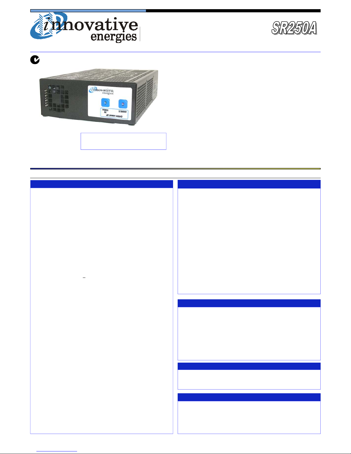
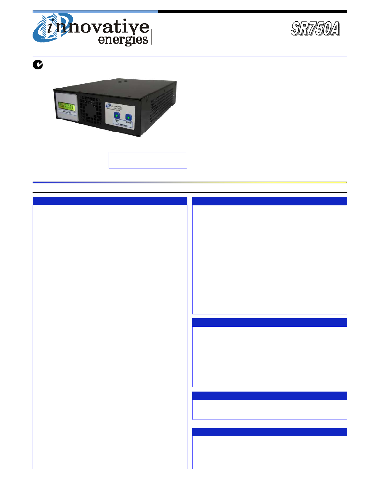
500 Watt
AC/DC Stand Alone Power Supply/Float Charger
incl. SR500D, SR500L
MODELS
Power Supply Battery Charger
Output
Volts
(factory default)
Output
Current (A)
Output
Volts*
(Charging)
Output
Current (A)
(Charging)
SR500A12 13.8
36.2
(41.6 @ 12V) 13.8 36.2 11-14
SR500A24 24 20.8 27.6 18.2 22- 2
SR500A30 30 16.6 34.5 14.5 28-36
SR500A36 36 13.8 41.4 12.0 34-43
SR500A48 48 10.4 55.2 .1 45-57
SR500A91 6 5.2 110 4.5 0-115
SR500A92 108 4.6 124 4.0 100-130
SR500A93 120 4.1 138 3.6 110-145
Adjustable
range (V)
MODEL IDENTIFICATION CODES
SR500A 12 T F S L-LAN
LAN = ethernet (ASCII) LAN+ = ethernet (SNMP) 232 = RS232
485 = RS485 No = blank
Input voltage and front panel
standby switch:
Output DC Connector type:
Cooling
Temperature Compensation
DC output: Nominal voltage
A = Standard PSU/Float Charger
D = A version with alarms
L = D version with DC high alarm and optional comms port
Function
Power 500W
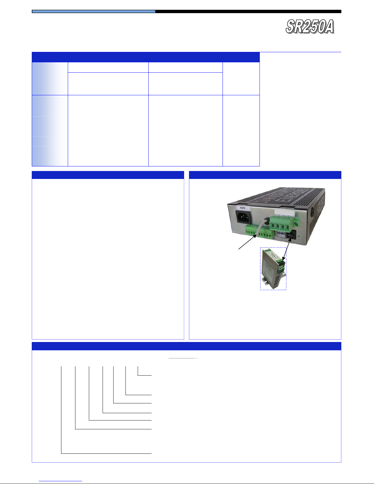
Optional communication port
for SR500L versions
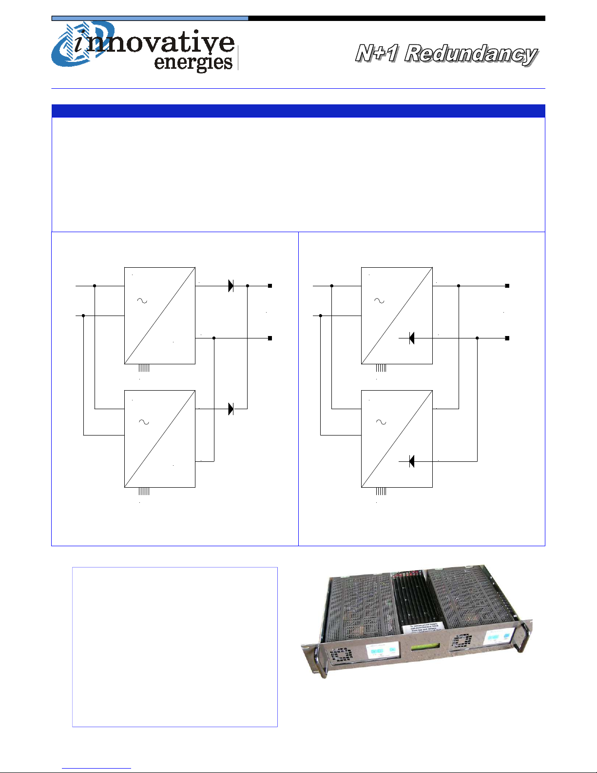
Rear view of SR500D….or SR500L...
with alarm contacts and no commu-
nication port option
L = 230V AC + switch Blank = 230V AC no switch
U = 110V AC + switch G = 110V AC no switch
H = 110V DC + switch J = 110V DC no switch
S = Stud X = Plug in /screw terminal block
F = Fan
T = Yes Blank = No
12, 24, 36, 48, 91 = 6V, 92 = 108V, 93 = 120V