innove duralam INTEGRA User manual

OPERATING INSTRUCTIONS


3
TABLE OF CONTENTS
INTRODUCTION ............................................................. 5
SAFETY INFORMATION ....................................................... 7
WARRANTY ................................................................ 9
ELECTRICAL SCHEMATICS ................................................... 10
SPECIFICATIONS ........................................................... 11
INSTALLATION ............................................................. 13
CONTROLS AND FEATURES
Main ON / OFF ........................................................... 14
Control Panel ............................................................ 14
Feeding Table (including feed guide–feed table Interlock) .......................... 15
Safety Shield (including Interlock) ............................................ 15
Film Mandrel ............................................................ 15
Film Tension Control .......................................................15
Heat Rollers ............................................................. 16
Pull Rollers .............................................................. 16
Rear Slitter .............................................................. 16
Circuit Breaker ........................................................... 16
OPERATING
Film Loading.......................................................... 17-23
Heat Setting ............................................................. 24
Speed Setting ........................................................... 24
Tension Control .......................................................... 24
MAINTENANCE
Cleaning Rollers .......................................................... 25
Cleaning Body Cover ........................................................25
Clearing a Film Jam (wrap–up) ............................................ 26-28
TROUBLESHOOTING GUIDE .................................................. 31

4

5
Thank you for your purchase of the Duralam Integra Laminator. The Duralam Integra features advanced
quartz heating technology and powerful DC motor drive for long term durability. Simple design with
eective safety controls ensure customer satisfaction! We look forward to many years of quality
laminating.
INTRODUCTION

6

7
SAFETY INFORMATION
Your safety as well as the safety of others is important. In this Instruction manual and on the product,
you will nd important safety messages regarding the product. Read these messages carefully. Read all
of the instructions and save these instructions for later use.
The safety alert symbol precedes each safety message in this instruction manual. The symbol indicates
a potential personal safety hazard to you or others, as well as product or property damage.
THE FOLLOWING WARNINGS ARE FOUND UPON THIS PRODUCT:
This safety message means that you could
be burned and your ngers and hands could
be trapped and crushed in the hot rollers.
Clothing, jewelry and long hair could be caught
in the rollers and pull you into them.
This message means you use caution when
near pull rollers. Pull rollers can grip and pull in
ngers, loose clothing, jewelry etc.
This safety message means that you could
get a severe burn if you come in contact with
the rollers. Use common sense and keep your
distance!
This message means you could cut yourself
if you are not careful.
WARNING: the safety alert symbol
precedes each safety message in this
instruction manual.
The symbol indicates a potential personal
safety hazard to you or others, as well as
product or property damage.
WARNING: do not attempt to service the or
repair the Duralam Integra laminator.
WARNING: do not connect the Duralam Integra
laminator to an electrical supply or attempt to
operate the laminator until you have completely
read these instructions.
Maintain these instructions with the Duralam
Integra at all times for operator reference.
CRUSH OR BURN HAZARD WARNING USE CAUTION
HOT SURFACE
SHARP BLADE

8

9
WARRANTY
SEE YOUR INNOVɮLOCATION OF PURCHASE TO CONFIRM COMPLETE WARRANTY TERMS
AND CONDITIONS. TERMS BELOW MAY VARY SLIGHTLY WITHIN EACH INNOVɮLOCATION.
Innové®Global Solutions warrants the Duralam Integra to be free from defects in material and
workmanship for a period of 1 year for parts from date of installation. This warranty is the only warranty
made by Innové® and cannot be modied or amended. Labour is covered by the installing dealer for
a period of 1 year from date of installation unless agreed to dierent terms at time of purchase. These
agreed terms must be clearly marked on the invoice and are between the installing dealer and customer.
Innove®Global Solutions sole and exclusive liability and the customer’s sole and exclusive remedy under
this warranty shall be, at Innové®Global Solutions option, to repair or replace any such defective part
or product. These remedies are only available if Innové®Global Solutions examination of the product
discloses to Innové®Global Solutions satisfaction that such defects actually exist and were not caused
by misuse, neglect, attempt to repair, unauthorized alteration or modication, incorrect line voltage, re,
accident, ood or other hazard.
Limited Warranty:
This warranty specically does not cover damage to the laminating rollers caused by knives, razor
blades, other sharp objects, failure caused by adhesives or improper use of the machine. Warranty
repair or replacement does not extend the warranty beyond the initial 90 day period from the date of
installation.
WARNING - Unauthorized customer alterations will void this warranty.
The warranty made herein is in lieu of all other warranties, expressed or implied, including any warranty
of merchantability or tness for a particular purpose. Innové®Global Solutions will not be liable for
property damage or personal injury (unless primarily caused by its negligence), loss of prot or other
incidental or consequential damages arising out of the use or inability to use the equipment.
Exclusions to the Warranty:
This warranty specically does not cover:
1. Damage to the laminating rollers caused by knives, razor blades, other sharp objects or failure caused
by adhesives.
2. Damage to the machine caused by lifting, tilting and/or any attempt to position the machine other
than rolling on the installed castors on even surfaces.
3. Improper use of the machine.
4. Damage due from unqualied person(s) servicing the machine. QUALIFIED: Any person(s) trained by
Innové®Global Solutions to perform service related work on such equipment.
10
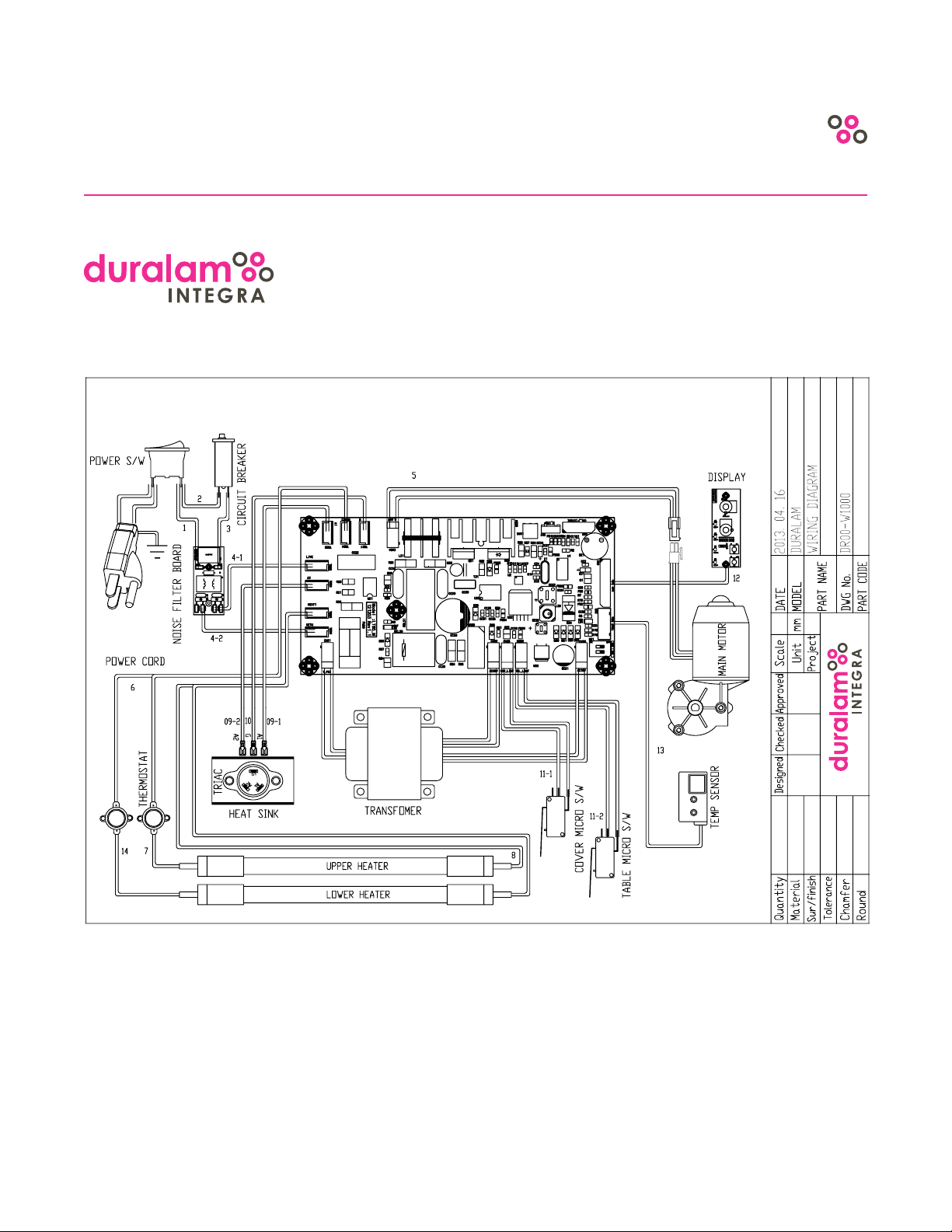
ELECTRICAL SCHEMATICS
Electrical Schematics (120 Volt)

11
ITEMS SPECIFICATIONS
Power Requirement AC 120V 60Hz
Power Consumption 1440W/12A
Dimension (WxLxH) 920mm x 470mm x 304.8mm (36.2”x18.5”x12”)
Warm–Up Time (mins.) 6
Max. Laminating Width 685mm (27”)
Laminating Film Thickness 1.2 mil - 5 mil
Weight 36kg (80lbs)
Heating System Infrared Heater
Temperature Adjustment System Variable 0º - 150ºC (0º-300ºF)
Temperature Control System Infrared System
Speed Control System Variable 0.3m - 1.52m /minute (1’ - 5’ /minute)
Main Motor DC Geared Motor
NOTE: The design / specications of the machine could be changed for improvement without any prior notice
SPECIFICATIONS

12

13
INSTALLATION
NOTE: Immediately check for shipping damage and report to shipping company.
HEAVY! Use two people to carefully lift laminator from box.
Place laminator on stable surface capable of supporting 150 lbs. The surface should be at least 30” high
for ergonomic work position (TechnOkart Recommended).
NOTE: Exit position of laminate should be clear to allow lm to drop to oor after lamination process.
Power Connection: Use only suitable grounded outlet. Ensure dedicated 110 volt/15amp circuit. Avoid
other equipment on same circuit to prevent nuisance fuse or circuit breaker tripping.
EXAMPLE: photocopier with laminator on same circuit will cause problems!

14
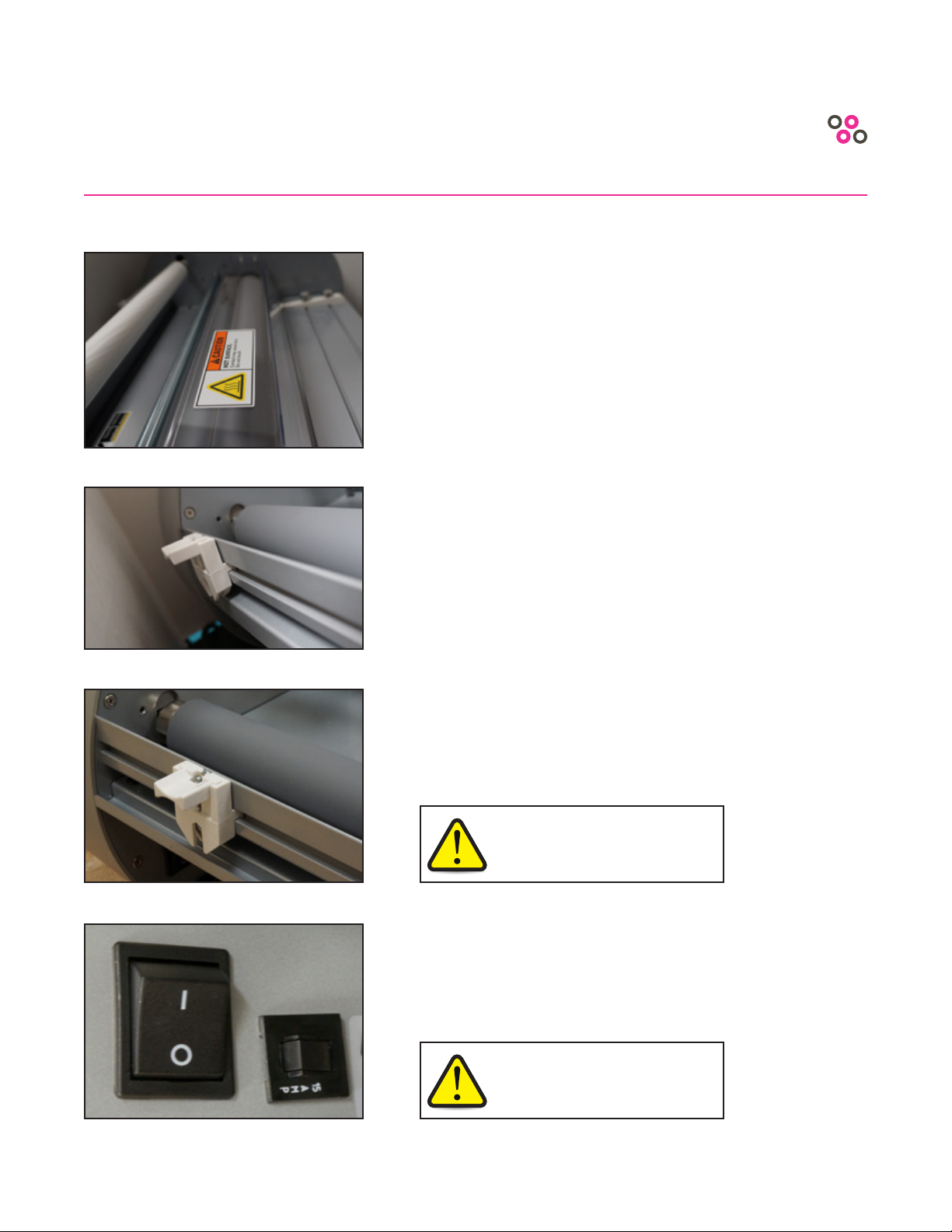
MAIN POWER SWITCH
• Located at the back of laminator
• Move switch to ON (I) position to turn main power on
• Move switch to OFF (O) position to turn main power o
CONTROL PANEL
Turn dial to adjust roller temperature to desired setting.
Refer to lm manufacturer for correct settings. NOTE:
Most lms run well at top heat setting. If low melt lm is
used a lower setting may be required.
“Auto-o” LED lights when laminator automatically
switches into this mode after 60 minutes of non–use. NOTE:
3 hours or bypass settings can be set by trained technicians.
NOTE: Auto-o feature only works when laminator is set at
80 degrees Celsius or higher.
Green “Ready” LED is on when roller temperature is
ready. Flashes if roller temperature is too hot.
Red “Power” LED is on when laminator is plugged in
and main ON / OFF switch is in the “ON” ( I ) position.
SPEED - Turn dial to adjust roller speed.
STOP - Stops rollers.
RUN - Activates rollers.
REVERSE - Press once to stop rollers. Press and hold to
reverse rollers to clear out jams. NOTE: Safety Back–up
Beeper sounds when reversing.
CONTROLS AND FEATURES

15
FEED TABLE WITH SAFETY INTERLOCK
• Used to position items for lamination
• Adjustable guide permits visual feeding
• Table safety interlock must be latched for operation
ON
OFF
FILM MANDREL
• Mandrel holds the roll of laminate
• Grippers keep roll securely fastened on mandrel
• Up to 1000’ rolls of 1” core 1.7 mil lm can be tted
FILM TENSION CONTROL
• To increase and decrease laminate lm tension
SAFETY SHIELD WITH SAFETY INTERLOCK
• Clear plastic ip shield protects operator
• When lifted, shield interlock stops motor drive
• Move shield to down position and press run to resume
CONTROLS AND FEATURES
16
HEAT ROLLERS
• Silicone rubber coated rollers have infrared heaters
enclosed
• Laminate lm is heated and glue activates as lm
travels over rollers
• Pressure is applied between rollers for beautiful
lamination results
PULL ROLLERS
• Pull rollers run simultaneously with heat rollers to
pull lamination to web exit position
REAR SLITTER
• Spring loaded cutter retracts for safety
• Used to cut lamination web at exit position
CIRCUIT BREAKER
• Electrical safety device
• Press to reset
CAUTION: Do not reach over the
laminator to operate the lm cutter.
WARNING: If the breaker trips a
second time after being reset, contact
your authorized dealer for service.
CONTROLS AND FEATURES
17
FILM LOADING
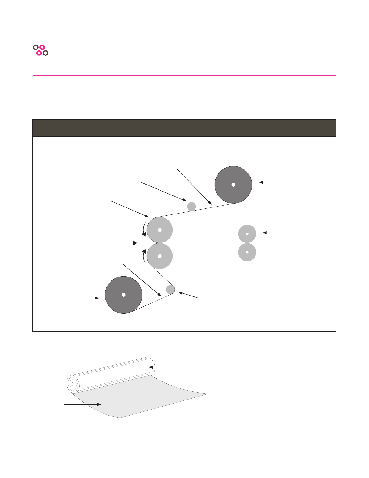
NOTE: Adhesive never touches
roller. Polyester surface always
touches roller.
OPERATING
Adhesive
Surface
Polyester
Surface
FILM THREADING DIAGRAM
Top
Film Roll
Pull Roller
Bottom
Idle Roller
Top Idle
Roller
Adhesive
Surface Side
Adhesive
Surface Side
Laminating
Roller
Laminating
Direction
Bottom
Film Roll
18
STEP 1 - Remove Feed Tray
• Lift safety shield
• Slide safety interlock latch on bottom right side
of feed tray (Refer to Figure 1)
• Lift and pull feed tray out
FIGURE 2
FIGURE 1
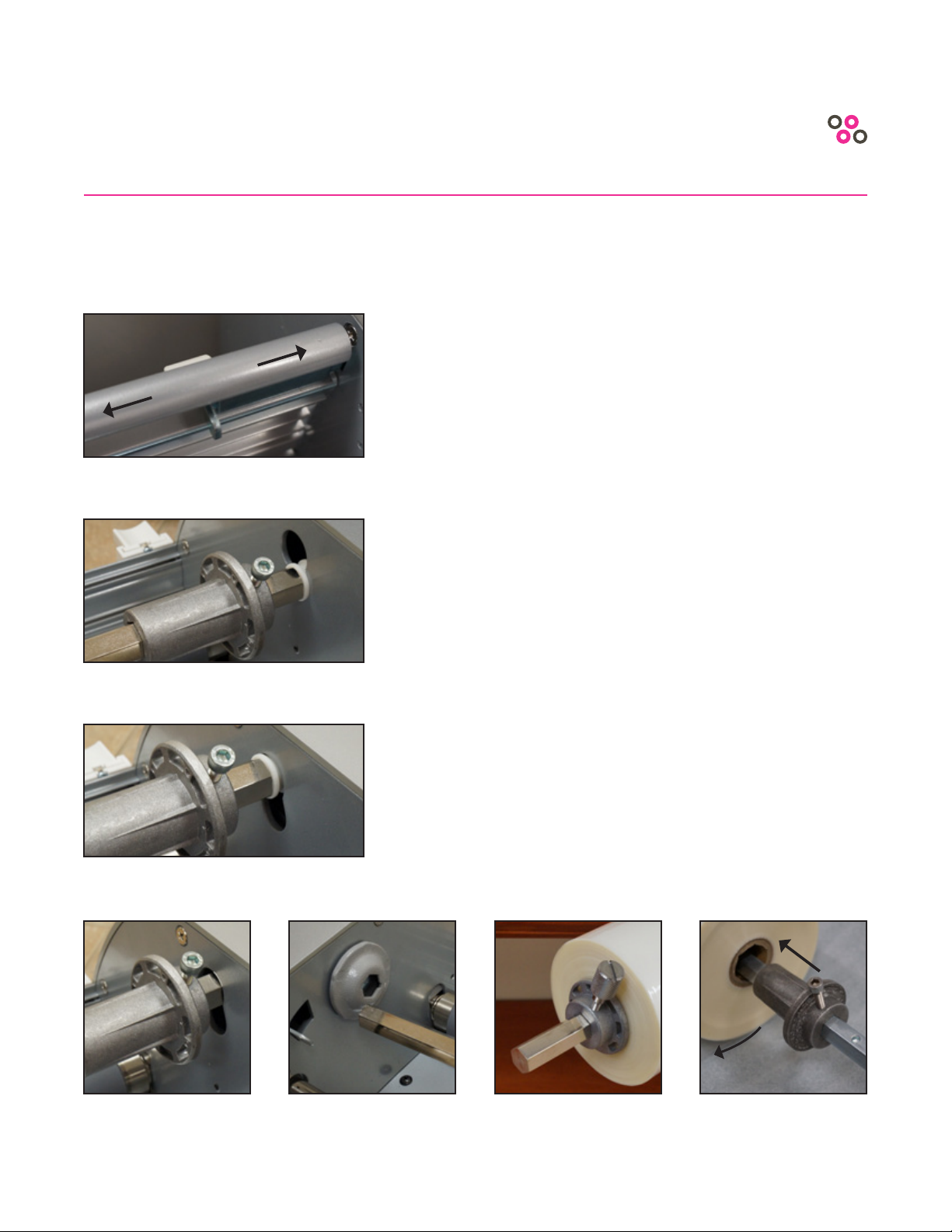
STEP 2 - Lift Bottom Film Mandrel Out of Laminator
• Lift right side of mandrel rst and slide mandrel
right until left side comes out of the hex head
(Refer to Figure 2 and 9)
STEP 3 - Slide Spent Film O Mandrel
• Remove left side gripper by loosening
thumb screw. (Refer to Figure 6)
FIGURE 3
FIGURE 4 FIGURE 5 FIGURE 6 FIGURE 7
OPERATING
ON
OFF
FILM LOADING Continued

19
FIGURE 9 (Direction of lm winding for BOTTOM
ROLL. Film gripper is removed for clarity.)
FIGURE 8 (Direction of lm winding for TOP
ROLL. Film gripper is removed for clarity.)
FIGURE 10 (lm gripper installed)
FIGURE 11 (left side lm gripper installed)
STEP 4 - New Film Loading
• Carefully note which way adhesive is wound on new
roll of laminate lm. 1” core laminate is normally wound
with adhesive in. Loading the lm backwards will
result in the hot rollers getting glued up and a jam will
occur. This is easily avoided by taking extra care when
threading laminate. Look closely at the pictures below
and note how the lm is threaded.
OPERATING
FILM LOADING Continued
20
OPERATING
FILM LOADING Continued
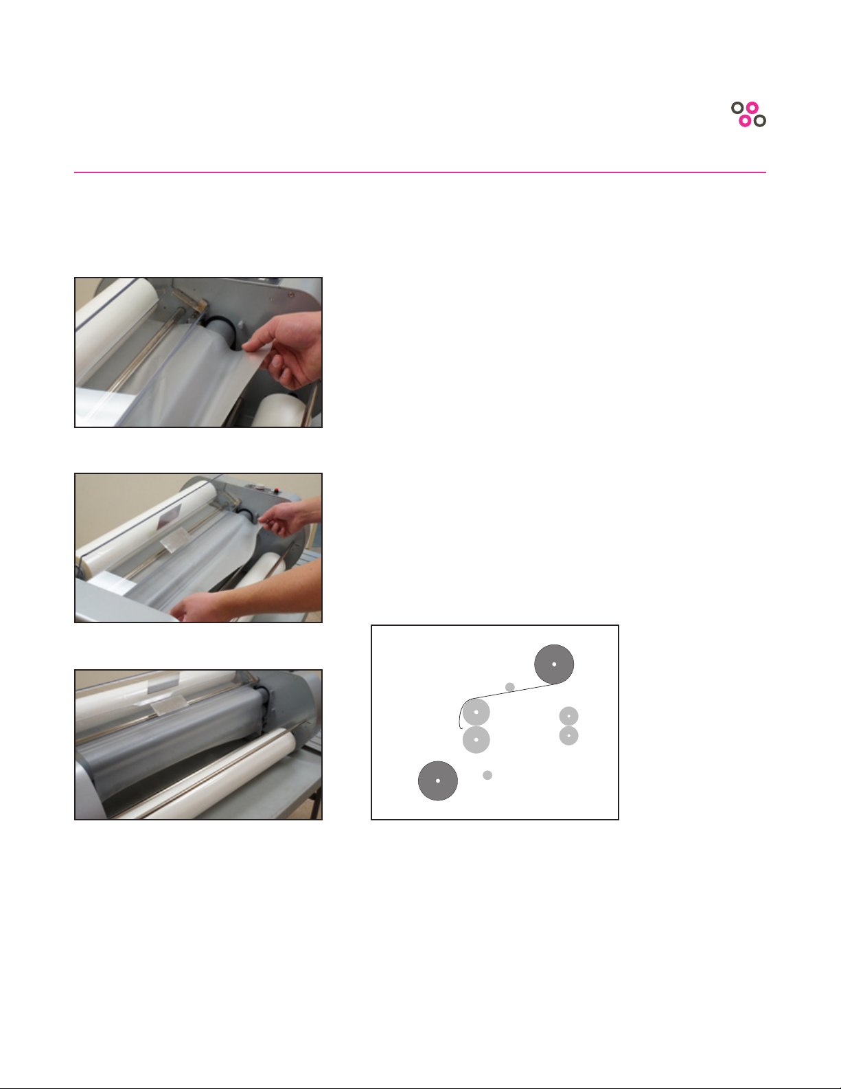
STEP 5 - Film Threading
• Pull top lm under top idle roller and hang
loosely over heat rollers (Refer to Figures 12-14
and Diagram 14a)
Figure 14a (Pull top lm under top idle roller)
FIGURE 13
FIGURE 12
FIGURE 14
Table of contents


