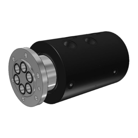
Moog GAT Rotostat Series User manual

Rotostat • Operating instructions

660000026, 2, en_GB
Translation of the original operating instructions
Moog GAT GmbH
Industriestraße 11
65366 Geisenheim
Telephone: +49 6722 93788-0
Fax: +49 6722 93788-110
Email: [email protected]
Internet: www.gat-mbh.de
Moog and GAT are registered trademarks of Moog Inc.
All trademarks as indicated herein are the property of Moog Inc. and its subsidiaries.
© 2021 Moog GAT GmbH. All rights reserved. All changes reserved.
Rotostat • Operating instructions
2

Table of contents
1 General............................................................................................................................................ 5
1.1 Information about these instructions....................................................................................... 5
1.2 Explanation of symbols........................................................................................................... 5
1.3 Copyright................................................................................................................................. 6
1.4 Warranty.................................................................................................................................. 6
1.5 Customer service.................................................................................................................... 6
2 Safety.............................................................................................................................................. 6
2.1 Proper use............................................................................................................................... 6
2.2 Basic hazards.......................................................................................................................... 6
2.3 Responsibility of the owner..................................................................................................... 8
2.4 Staff requirements................................................................................................................... 9
2.4.1 Qualifications........................................................................................................................ 9
2.5 Personal protective equipment................................................................................................ 9
3 Technical data.............................................................................................................................. 10
3.1 Operating conditions............................................................................................................. 10
3.2 Leakage rate......................................................................................................................... 10
3.2.1 Rotostat A.......................................................................................................................... 10
3.2.2 Rotostat E........................................................................................................................... 11
3.2.3 Rotostat N........................................................................................................................... 11
3.3 Type plate.............................................................................................................................. 12
4 Construction and function.......................................................................................................... 12
4.1 Type key................................................................................................................................ 12
4.2 General description of the Rotostat series............................................................................ 13
4.3 Rotostat A............................................................................................................................. 13
4.4 Rotostat E............................................................................................................................. 14
4.5 Rotostat N............................................................................................................................. 14
4.6 Rotokombi (option)................................................................................................................ 15
5 Transportation, packaging and storage..................................................................................... 16
5.1 Safety instructions ................................................................................................................ 16
5.2 Inspection on receipt of delivery............................................................................................ 17
5.3 Packaging............................................................................................................................. 17
5.4 Symbols on the packaging.................................................................................................... 17
5.5 Transport............................................................................................................................... 18
5.6 Storage.................................................................................................................................. 19
6 Installation and initial commissioning....................................................................................... 19
6.1 Safety instructions................................................................................................................. 19
6.2 Risk of material damage to the device.................................................................................. 20
6.3 Preparations.......................................................................................................................... 21
Rotostat • Operating instructions
3

6.4 Installation............................................................................................................................. 21
6.4.1 General.............................................................................................................................. 21
6.4.2 Preparing for installation.................................................................................................... 22
6.4.3 Installing the complete device............................................................................................ 22
6.4.4 Installing the cartridge elements (Rotostat A and N only).................................................. 24
6.4.5 Hydraulic switch................................................................................................................. 26
6.5 Initial commissioning............................................................................................................. 27
7 Maintenance................................................................................................................................. 27
7.1 Safety instructions ................................................................................................................ 27
7.2 Maintenance schedule.......................................................................................................... 28
7.3 Maintenance work................................................................................................................. 28
7.3.1 Cleaning the device............................................................................................................ 28
7.3.2 Checking the media lines................................................................................................... 28
7.3.3 After a completed maintenance......................................................................................... 29
8 Faults............................................................................................................................................. 29
8.1 Fault indicators...................................................................................................................... 29
8.2 How to act in case of faults................................................................................................... 29
9 Disassembly and disposal.......................................................................................................... 29
9.1 Safety instructions ................................................................................................................ 29
9.2 Disassembly.......................................................................................................................... 30
9.3 Disposal................................................................................................................................ 30
10 Index.............................................................................................................................................. 31
Rotostat • Operating instructions
4

1 General
1.1 Information about these instruc-
tions
This manual enables you to handle the device in a
safe and efficient manner. This manual is part of
the device and must be kept in its vicinity in order
to ensure that it is available to the personnel at all
times.
The personnel must have carefully read and
understood this manual before commencing any
work. The compliance with all safety information
and instructions provided in this manual is essen-
tial for safe operation.
Furthermore, all local work protection and general
safety regulations applicable at the device's place
of installation must be observed.
The illustrations used throughout this manual are
intended to provide a general understanding and
may deviate from the actual model of the machine.
These instructions apply to the Rotostat series,
types:
nRotostat A (AX, AW, AL)
nRotostat E (EX, EW, EL)
nRotostat N (NX, NW)
Additional information
The following documents may include further infor-
mation on the device:
nEnclosed test reports
nOrder documents
nDrawings
nType plate
nOperating instructions for the additional compo-
nents (optional Rotokombi)
1.2 Explanation of symbols
Safety instructions
Safety instructions are marked with symbols in
these instructions. The safety instructions are
introduced with signal words, which express the
degree of endangerment.
DANGER!
This combination of symbol and signal
word indicates an immediately dangerous
situation that can cause death or severe
injuries if it is not avoided.
WARNING!
This combination of symbol and signal
word indicates a possibly dangerous situa-
tion that can cause death or severe inju-
ries if it is not avoided.
CAUTION!
This combination of symbol and signal
word indicates a possibly dangerous situa-
tion that can cause slight injuries if it is not
avoided.
NOTICE!
This combination of symbol and signal
word indicates a possibly dangerous situa-
tion that can cause property and environ-
mental damage if it is not avoided.
Tips and recommendations
This symbol highlights useful tips and rec-
ommendations as well as information
designed to ensure efficient and smooth
operation.
Rotostat • Operating instructions
5

1.3 Copyright
The contents of these instructions are copyrighted.
Their use is permitted in the context of using the
device. Any use extending beyond this is not
allowed without written permission from the manu-
facturer.
1.4 Warranty
The warranty provisions are included in the manu-
facturer's general terms and conditions.
In order to be able to make warranty claims, the
device must be sent to the manufacturer.
Subject to change without prior notice.
1.5 Customer service
Contact our customer service in case of technical
questions:
Address Moog GAT GmbH
Industriestraße 11
65366 Geisenheim
Telephone +49 6722 93788-0
Fax +49 6722 93788-110
email [email protected]
Internet www.gat-mbh.de
We are also always interested in information and
experiences you have gained while using our prod-
ucts, and which could help us improve our prod-
ucts.
2 Safety
2.1 Proper use
Rotostat are used exclusively as a rotary feed-
through for transferring media. These instruc-
tions, the type plate, the order documents and
drawings are recognised as valid sources of
information on specifications, operating condi-
tions, limits for use, areas of application.
Proper use also includes adherence to all details in
these instructions.
Any use which exceeds or differs from the proper
use counts as misuse.
WARNING!
Danger as a result of misuse!
Misuse of the Rotostat can cause dan-
gerous situations.
– Never connect the coded connections
incorrectly.
– Never exceed the performance limits,
e.g. the maximum pressure and max-
imum revolutions.
– Never admit any media other than
those media specified for the specific
device. See the order documents for
specifications.
– Never step on the device.
– Never open the device.
2.2 Basic hazards
The following section indicates residual risks which
may be caused by the device even when it is used
for its proper use.
Rotostat • Operating instructions
6

Electric power
DANGER!
Danger to life from electric power!
As a Rotokombi, the device can be com-
bined with slip rings which carry current. If
live parts of the device are touched, there
is immediate danger to life from electric
shock. Damage to the insulation or indi-
vidual components can be life threatening.
– Only allow work on the electrical
system to be performed by an electri-
cian.
– In case of damage to the insulation,
switch off the voltage supply immedi-
ately and initiate repair.
– Before beginning work on active parts
of electrical systems and equipment,
de-energise and secure for the dura-
tion of the work.
– Keep humidity away from energised
parts. This can cause short-circuiting.
Rotating parts
WARNING!
Danger of injury due to rotating parts!
Rotating parts of the device Severe inju-
ries can result from pulling in, winding up
or catching.
– Do not reach into or hang on rotating
parts during operation.
– Before all work near the rotating parts,
bring the movements to a standstill and
secure against switching on.
– In the danger zone, wear close-fitting
protective clothing with low tear
strength.
Rotokombi
WARNING!
Danger of injury due to rotating parts!
Due to the combination of several rotating
components and their torque supports,
there may be new hazard points which can
cause crushing.
See also required operating instructions
for the Rotokombi sealing system in ques-
tion.
– Perform risk assessment.
– If necessary, install or adapt separating
protective device.
– See the other required operating
instructions for the Rotokombi sealing
system in question (Rotopack, Roto-
stat, etc.).
Pneumatic system
WARNING!
Danger of injury due to pneumatic
energy!
Escaping compressed air can cause
extremely severe injuries.
– Only allow work on the pneumatic
system to be performed by a pneu-
matic expert.
– Before beginning work on the pneu-
matic system, de-pressurise it com-
pletely. Completely de-pressurise pres-
sure accumulator.
– Always heed the specification of the
maximum pressure for the device. With
pressures higher than expected, do not
start up the device.
Rotostat • Operating instructions
7

Hydraulic system
WARNING!
Danger of injury due to liquids under
pressure!
Sudden releases of pressure and a stream
of liquid escaping under pressure can
cause injuries.
– Only allow work on the hydraulic
system to be performed by a hydraulic
expert.
– Only begin work on systems with pres-
sure accumulator after complete
release of the hydraulic pressure and
checking of the de-pressurisation.
– Never hold body parts or objects in a
stream of liquid.
– Catch and dispose of escaping liquids
properly.
Hot surfaces
WARNING!
Risk of injury from warm or hot sur-
faces.
Hot media and the rotation of the device
can cause the surfaces of components to
heat up considerably during operation.
Skin contact with hot surfaces causes
serious skin burns.
– When performing any work in the
vicinity of hot surfaces you must
always wear heat-resistant occupa-
tional safety clothing and protective
gloves.
– Before any work make sure that all sur-
faces have cooled to ambient tempera-
ture.
– Never cover warm or hot surfaces. This
can cause overheating.
2.3 Responsibility of the owner
The owner is the person who uses the device for
commercial or economic purposes or authorises
use/operation by a third party and bears the legal
product responsibility for the protection of the user,
staff or third parties during operation.
The device is used in the commercial sector. The
owner of the device is therefore subject to the legal
occupational safety requirements.
The following in particular applies:
nThe owner must familiarise themselves with the
applicable occupational safety regulations and
also conduct a risk assessment to determine
additional risks that may arise due to the spe-
cific working conditions at the place of use of
the device. They must implement these in the
form of operating instructions for the operation
of the device.
nDuring the entire operating time of the device,
the owner must check whether the operating
instructions established by the owner are in line
with the respective current applicable rules and
standards, and must adjust them if necessary.
nThe owner must clearly organise and define
the responsibilities for installation, operation,
fault clearance, maintenance and cleaning.
nThe owner must make sure that all personnel
who come into contact with the device have
read and understood these instructions. In
addition, the owner must train staff at regular
intervals and inform the staff of the hazards.
nThe owner must provide staff with the required
safety clothing and equipment and instruct
them on the compulsory wearing of the
required safety equipment.
Furthermore, the owner is responsible for ensuring
that the device is always in technically perfect
working condition.
Rotostat • Operating instructions
8

2.4 Staff requirements
2.4.1 Qualifications
WARNING!
Danger due to insufficiently qualified
personnel!
Insufficiently qualified personnel are not
capable of assessing the risks when using
the device and expose themselves and
others to the risk of serious or even fatal
injuries.
– All work must be carried out by appro-
priately qualified personnel only.
– Insufficiently qualified and unauthor-
ised personnel must be kept away from
the danger and working zone.
Only personnel who can be expected to carry out
this work reliably are authorised as staff. Per-
sonnel whose reactions are impaired, e.g. by
drugs, alcohol or medication, are not authorised.
The required qualifications for personnel and the
various tasks are listed in these instructions as fol-
lows:
Electrician
Due to his professional knowledge, training and
experience, as well as his knowledge of the appli-
cable standards and regulations, the electrician is
in a position to perform work on electrical systems
and to detect and avoid possible dangers by him-
self.
The electrician is trained specially for his work
environment and is familiar with the relevant stan-
dards and regulations.
Specialist staff
Specialist staff are capable of carrying out the
assigned work and identifying and preventing pos-
sible hazards independently due to their specialist
qualification, knowledge and experience of han-
dling rotary feedthrough and familiarity with the
valid standards and regulations.
Transport specialist
The transport specialist is trained to perform trans-
port work with a crane or forklift. The transport
specialist is able to choose suitable fastening
equipment according to transport requirements
and handle it professionally. The transport spe-
cialist has been trained for transportation by fork
lift on the machine and is able to operate it.
The transport specialist is trained specially for the
work environment in which they are active and is
familiar with the relevant regulations.
Depending on the area of application, additional
knowledge of working in explosive areas and of
using special tools and aids may be required.
2.5 Personal protective equipment
Personal protective equipment serves to protect
people against hazards to their safety and health
while working.
The personnel must wear the personal protective
equipment while working on and with the device
which is referred specially to in the individual sec-
tions of these instructions.
Description of the personal protective equip-
ment
The personal protective equipment is explained
below:
Industrial helmet
Industrial helmets protect the head against falling
objects, swinging loads and impacts with fixed
objects.
Protective gloves
Rotostat • Operating instructions
9

Protective gloves protect the hands from friction,
abrasions, cuts or deep wounds and from contact
with hot surfaces.
Protective work clothing
Protective work clothing consists of tight-fitting
work clothing with low breaking strength, tight
sleeves and no parts that stick out.
Safety shoes
Safety shoes protect the feet from crushing, from
dropping parts, and from slipping on slippery
floors.
3 Technical data
The technical data for the device, such as max-
imum pressure, flow, maximum rotational speed,
weight, torque values and other performance data
depend on the specific version. Refer to the type
plate, the order documents and any drawings
which may also be included for this information.
A data sheet is available for standard devices.
Drawings are available for special models.
3.1 Operating conditions
Environment
nTemperature range: -20 to +80 °C
nMaximum relative humidity, non-condensing: 0
to 80 %
nProtection class as per type plate
3.2 Leakage rate
Typical leakage rate:
3.2.1 Rotostat A
Medium Revolution speed Rotostat
30 A 50 A 65 A 80 A
Hydraulic fluid with a vis-
cosity of 20 cm2/s at 7.0 MPa
[in l/min]
Without revolution
speed
0.075 0.12 0.15 0.3
At 1500 min-1 0.15 0.2 0.4 0.7
At 3000 min-1 0.2 0.4 0.6 1
Cooling lubricant with a viscosity of 20 cm2/s at
7.0 MPa
[in l/min]
1 1.7 2.1 4
Air at 20 °C, 2 cm2/s and 0.6 MPa
[in Nl/min]
28 47 54 64
Rotostat • Operating instructions
10

Medium Revolution speed Rotostat
100 A 125 A 150 A
Hydraulic fluid with a viscosity of
20 cm2/s at 7.0 MPa
[in l/min]
Without revolution
speed
0.4 0.7 1
At 1500 min-1 0.9 1.6 2.3
At 3000 min-1 1.5 2.5 3.4
Cooling lubricant with a viscosity of 20 cm2/s at 7.0 MPa
[in l/min]
5.3 8.4 11
Air at 20 °C, 2 cm2/s and 0.6 MPa
[in Nl/min]
83 104 121
The leakage rate values only depend on pressure and viscosity on low-viscose media.
All values were determined during test and do depend on the operational conditions. Deviations are there-
fore possible. The value indicated in the test log always applies.
3.2.2 Rotostat E
Medium Rotostat
25 E 40 E 60 E 80 E
Hydraulic fluid with a viscosity of 46 cm2/s at
21.0 MPa [in cm3/min]
100 500 850 1050
Air at 20° C and 0.6 MPa [in Nl/min] 110 250 450 700
All values were determined during test and do depend on the operational conditions. Deviations are there-
fore possible. The value indicated in the test log always applies.
3.2.3 Rotostat N
Hydraulic fluid with a viscosity of 20 cm2/s at 15.0 MPa
Revolution speed [min-1]Rotostat
30 NX 80 NX 140 NX 200 NX
0 0.2 0.6 1.3 2.6
1500 0.3 1.2 2.7 4.5
3000 0.5 1.7 3.4 -
The leakage values depend on pressure and viscosity on low-viscosity media and is at about 12 to 15
times higher than the values for the revolution speed 0.
The value indicated in the test log always applies.
Rotostat • Operating instructions
11

3.3 Type plate
The type plate is situated on the housing. The type
plate differs depending on the specific device and
may contain the following information:
nManufacturer
nType
nItem number
nSerial number
nOrder number
nMaximum pressure
nMaximum speed
4 Construction and function
4.1 Type key
Rotostat A
Fig. 1: Rotostat A
Size / shaft diameter (specification are always
required)
Rotostat A
Medium: (Specification always required)
X - Oil, emulsion
W - Water
L - Air
Number of ways (specification always required)
Medium: (Specification as required)
X - Oil, emulsion
W - Water
L - Air
Number of ways (specification if required)
Shaft end: (Specification always required)
0 - closed
1 - open
Rotostat E
Fig. 2: Rotostat E
Size / shaft diameter (specification are always
required)
Rotodisk E
Medium: (Specification always required)
X - Oil, emulsion
W - Water
L - Air
Number of ways (specification always required)
Medium: (Specification as required)
X - Oil, emulsion
W - Water
L - Air
Number of ways (specification if required)
Shaft end: (Specification always required)
0 - closed
1 - open
Material (specification always required)
210 - 21 MPa
350 - 35 MPa
420 - 42 MPa
Special text (Specification as required)
Rotostat N
Fig. 3: Rotostat N
Size / shaft diameter (specification are always
required)
Rotodisk N
Rotostat • Operating instructions
12

Medium: (Specification always required)
X - Oil, emulsion
W - Water
L - Air
Number of ways (specification always required)
Medium: (Specification as required)
X - Oil, emulsion
W - Water
L - Air
Number of ways (specification if required)
Shaft end: (Specification always required)
0 - closed
1 - open
Material (specification always required)
210 - 21 MPa
350 - 35 MPa
420 - 42 MPa
4.2 General description of the Roto-
stat series
The Rotostat rotary feedthrough is done via the
primary seal, generally via a patented hydro-static
control mechanism.
The primary seal refers to the sealing of the actual
feedthrough channel or channels. The seal on any
leak chambers which may be in place is referred to
as the secondary seal.
4.3 Rotostat A
Brief description
Rotostat A are rotary feedthrough with gap seals
for the transfer of fluids during medium pressures
and high speeds.
The sealing in-between stationary and rotating
parts is done via the seal gap, which are kept at
their default value via a patented hydro-static con-
trol mechanism that allows a tumble and irregular
running of the shaft.
Even during high speeds and pressures only vis-
cose friction occurs and therefore only a small, cal-
culated heat formation. The heat is dissipated via
the inherent occurring leak. The leakage losses
are in a small, pre-calculated limits.
Rotostat A is not subject to temperature fluctua-
tions and pressure impacts due to its design.
Fig. 4: Superstructure Rotostat A
Models
Rotostat A is available in two models:
nCartridge element
nComplete rotary feedthrough to the superstruc-
ture
Technical properties
nNo static friction and stick/slip effects
nMedium operating pressure at simultaneous
high speeds
nMinor leak
nMinor mechanical performance loss
nHighly resistance to temperatures
nAlmost any fluid is possible, even non-lubri-
cating ones
nMaintenance free
Rotostat • Operating instructions
13

Transfer media
nOil
nEmulsions and non-lubricating fluids
nAir and gas
4.4 Rotostat E
Brief description
Rotostat E are rotary feedthrough with gap seals
for the transfer of fluids during medium pressures
and medium speeds.
The sealing between the stationary and rotating
parts is done via a patented, hydro-static con-
trolled "Floating sleeve". These "Floating sleeves"
are movable arranged. The hydro-static forces
centre the "Floating sleeve" on the rotating shaft.
Even during high speeds and pressures, only vis-
cose friction occurs and therefore only a small, cal-
culated heat formation. The heat is dissipated via
the inherent occurring leak. The leakage losses
are in a small, pre-calculable limits.
Fig. 5: Superstructure Rotostat E
Models
nComplete rotary feedthrough to the superstruc-
ture
Technical properties
nNo static friction and stick/slip effects
nMedium operating pressure at simultaneous
high speeds
nMinor leak
nMinor mechanical performance loss
nHighly resistance to temperatures
nAlmost any fluid is possible, even non-lubri-
cating ones
nViscosity range from 1 to 1000 cSt
nMany inert gases
nMaintenance free
Transfer media
nOil
nEmulsions and non-lubricating fluids
nAir and gas
4.5 Rotostat N
Brief description
Rotostat N are rotary feedthrough with gap seals
for the transfer of fluids during medium pressures
and high speeds.
The seals in-between stationary and rotating parts
is done via the seal gap, which are kept at their
default value via a patented hydro-static control
mechanism that allows a tumble and irregular run-
ning of the shaft.
Even during high speeds and pressures, only vis-
cose friction occurs and therefore only a small, cal-
culated heat formation. The heat is dissipated via
the inherent occurring leak. The leakage losses
are in a small, pre-calculable limits.
Rotostat N is not subject to temperature fluctua-
tions and pressure impacts due to its design.
Rotostat • Operating instructions
14

Fig. 6: Superstructure Rotostat N
Mode of operation
Fig. 7: Mode of operation
Rotor
Stator
Medium
VHMain current
VRControl current
VVLeakage current
A complex, inverse hydrostatic gap regulator
ensures that even at high pressures, the gap
between stationary and rotating parts are kept at
few μm, so that returning leakage is very low. Due
to its design for stress, the Rotostat N is insensi-
tive to temperature variations, dirt and pressure
impacts.
Models
Rotostat N is available in two models:
nCartridge element
nComplete rotary feedthrough to the superstruc-
ture
Technical properties
nNo static friction and stick/slip effects
nMedium operating pressure at simultaneous
high speeds
nMinor leak
nMinor mechanical performance loss
nHighly resistance to temperatures
nAlmost any fluid is possible, even non-lubri-
cating ones
nViscosity range from 1 to 1000 cSt
nMaintenance free
Transfer media
nOil
nEmulsions and non-lubricating fluids
4.6 Rotokombi (option)
The Rotokombi design makes it possible to com-
bine the devices with all the manufacturer's other
media feedthroughs. The devices can be com-
bined with additional components for gas, water,
grease and oil for transferring electrical currents
and air. The optimal sealing technology is used for
each medium.
Rotostat • Operating instructions
15

Example
Fig. 8: Example of a Rotokombi with Rotoflux and
Rotopack
Advantages of the Rotokombi technology
nModular structure
nNo limit for the media to be transmitted
nComplete solution from a single source
nNo interface problems between the individual
components
nCan be combined with other manufacturers'
components
Safety
For Rotokombis it is imperative that you
adhere to the operating instructions for all
the devices used.
The combination with other components and
transfer of other media may cause additional haz-
ards. If necessary, the operator must take addi-
tional measures.
5 Transportation, packaging
and storage
5.1 Safety instructions
Suspended loads
WARNING!
Danger of fatal injury from suspended
loads!
During lifting operations, loads may swing
out and fall down. This may result in
serious injury or death.
– Never step under suspended loads,
and do not step within their pivoting
range.
– Only move loads under supervision.
– Only use approved hoists and lifting
gear with a sufficient load-bearing
capacity.
– Do not use torn or abraded hoists such
as ropes and straps.
– Do not place hoists such as ropes and
straps against sharp edges or corners
and do not knot or twist them.
– Set the load down when leaving the
workplace.
Rotostat • Operating instructions
16

Improper transport
NOTICE!
Damage to property due to improper
transport!
Transport units may fall or tip over as a
result of improper transport. This can
cause a significant level of property
damage.
– Proceed carefully when unloading
transport units at delivery and during
in-house transport; observe the sym-
bols and instructions on the packaging.
– Only use the attachment points pro-
vided.
– Only remove the packaging shortly
before assembly.
5.2 Inspection on receipt of delivery
On receipt, immediately inspect the delivery for
completeness and transport damage.
Proceed as follows in the event of externally appa-
rent transport damage:
nDo not accept the delivery, or only accept it
subject to reservation.
nNote the extent of the damage on the transport
documentation or the shipper's delivery note.
nInitiate complaint procedures.
Issue a complaint in respect of each defect
immediately following detection. Damage
compensation claims can only be asserted
within the applicable complaint deadlines.
5.3 Packaging
About packaging
The individual packages are packaged in accord-
ance with anticipated transport conditions. Only
environmentally-friendly materials have been used
in the packaging.
The packaging is intended to protect the individual
components from transport damage, corrosion and
other damage prior to assembly. Therefore do not
destroy the packaging and only remove it shortly
before assembly.
Handling of packaging materials
Either keep packaging material for a later shipping
or store the device according to the respectively
applicable legal provisions and local regulations.
NOTICE!
Risk of environmental damage from
incorrect disposal!
Packaging materials are valuable raw
materials and can in many cases be used
again or prepared sensibly and recycled.
Incorrect disposal of packaging materials
can cause environmental hazards.
– Dispose of packaging materials in an
environmentally-friendly fashion.
– Heed the local disposal regulations.
Have disposal carried out by a spe-
cialist company as necessary.
5.4 Symbols on the packaging
The following symbols may be affixed to the pack-
aging. Always adhere to the symbols during trans-
portation.
Attach here
Only use means of attachment (chain sling, lifting
strap) in the places marked with this symbol.
Rotostat • Operating instructions
17

Protect from heat
Protect packages against heat and direct sunlight.
Protect against moisture
Protect packages against moisture and keep dry.
Fragile
Marks packages with fragile or sensitive contents.
Handle the package with care; do not allow to fall
and do not expose to impacts.
Do not damage air-tight packaging
The packaging is air-tight. Damage to the barrier
layer may render the contents unusable.
Do not pierce. Do not use sharp objects to open.
5.5 Transport
Depending on the model of the device, transport
with a fork lift may be necessary.
Transportation of pallets with the fork lift
Transport packages which are fastened on pallets
can, under the following conditions, be transported
with a fork lift:
nThe fork lift must be engineered for the weight
of the packages.
nThe package must be fastened securely to the
pallet.
nThe fork lift driver must be authorised to drive
industrial trucks with a driver's seat or driver's
stand in accordance with the local valid regula-
tions.
Transportation
Personnel:
nTransport specialist
Protective equipment:
nIndustrial helmet
Fig. 9: Transportation by fork lift
1. Drive the fork lift with the forks between or
under the rails of the pallet.
2. Insert the forks so that they protrude on the
opposite side.
3. Make sure that the pallet cannot tip if the
centre of gravity is not in the middle.
4. Lift the pallet with the package and begin
transportation.
Rotostat • Operating instructions
18

5.6 Storage
The device contains plastic elements whose prop-
erties can be changed by environmental influences
such as oxygen, ozone, heat, humidity, light, UV
rays and solvents.
Store the device under the following conditions:
nDo not store near heating bodies or other
sources of heat.
nDo not store in the same room with solvents,
chemicals, acids, fuels, disinfectants or similar
substances.
nNot in proximity to fluorescent light sources,
mercury vapour lamps, light sources, electric
motors or devices which can generate sparks
or an ozone charge due to other electrical dis-
charges.
nDo not subject to direct sunlight or open
installed fluorescent tubes which could gen-
erate a UV load.
nDo not place on copper, brass or rusty steel.
nStore dry and dust-free.
nIf possible, store in air and light-resistant orig-
inal packaging and only unpack shortly before
use.
nStorage temperature: 5 to 25 ℃
nRelative humidity: 65 %
nSpare seals: Store voltage-free, do not bend,
fold, knick, hang on hooks or expose to pres-
sure loads.
nMaximum storage time: 12 months After that,
send back to manufacturer for inspection.
Under some circumstances, there are
notes about storage on the packaging
pieces which exceed the requirements
named here. Adhere to these accordingly.
6 Installation and initial com-
missioning
6.1 Safety instructions
WARNING!
Risk of injury from missing media line
connections!
Media may leak if connections are made
incorrectly. Contact with the leaked media
can cause serious injuries.
– Connect the media and leak connec-
tions properly to the corresponding
supply aggregates.
– Adhere to the engraved markings for
the connection bores on the housing
and clearly identify the connections
using the information in the drawings
included with delivery.
CAUTION!
Risk of crushing from the dead weight
of the component!
If the device falls down during assembly, it
can crush hands or feet due to its weight.
– Handle the device carefully. Do not let
it fall. If necessary, secure it with a suit-
able hoisting device.
– Wear safety shoes.
Rotostat • Operating instructions
19

6.2 Risk of material damage to the
device
Radial jamming on the outer diameter
NOTICE!
Risk of material damage due to radial
jamming on the outer diameter.
The additional, non-calculated forces
which are generated when attaching addi-
tional components to the device can cause
bearing damage.
– Never attach additional components to
the outer diameter of the device.
Static indetermination
NOTICE!
Risk of material damage due to static
indetermination or centrifugal force.
The device is not suitable for absorbing
forces, e.g. static indetermination or centri-
fugal force.
– Only use the device in the environment
as approved by the manufacturer and
for the agreed purpose.
Static overdetermination
NOTICE!
Risk of material damage from static
overdetermination.
Static overdetermination is generated by
screwing the rotor and stator to the sur-
rounding. If no suitable measures are
taken to prevent the resultant forces, this
installation can cause the destruction of
the device.
– Only use the device in the environment
as approved by the manufacturer and
for the agreed purpose.
Missing seal
NOTICE!
Risk of material damage due to missing
seal.
Damage to the sealing system can lead to
damage to the device.
– Do not remove the lubricant from the
sliding discs.
– Adhere to the existing installation
dimensions for cartridge elements.
– Do not hit or knock sliding discs or sub-
ject them to any other form of mechan-
ical strain.
Rotostat • Operating instructions
20
This manual suits for next models
8
Table of contents
Other Moog Industrial Equipment manuals
Popular Industrial Equipment manuals by other brands

Karibu
Karibu 62954 Assembly and operating instructions

Larzep
Larzep SM INSTRUCTIONS & MAINTENANCE SHEET
ABB
ABB Dodge Quantis BU383 manual

Montanari
Montanari M50P Directions for installation, use and maintenance

Nexen
Nexen AIR CHAMP 130-19 user manual

Bühler technologies
Bühler technologies GAS 222.35 Brief instructions
