Zaber X-LRQ-DEC Series User manual

X-LRQ-DEC Series User's Manual
High precision stages with built-in controllers and linear encoders and dust covers
Disclaimer
Zaber’s devices are not intended for use in any critical medical, aviation, or military applications or
situations where a product's use or failure could cause personal injury, death, or damage to property.
Zaber disclaims any and all liability for injury or other damages resulting from the use of our products.
Precautions
Zaber’s motion control devices are precision instruments and must be handled with care. In
particular, moving parts must be treated with care. Avoid axial loads in excess of the rated thrust
load, axial and radial impact, dust and other contaminants and damage to the drive components.
These will reduce the performance of the device below stated specifications.
Lubrication of linear guides
The X-LRQ-DEC series of linear stages use recirculating ball bearing linear guides to support and
guide the stage top of the device. These linear guides require lubrication in order to achieve the
longest possible lifetime at the highest possible performance. At the rated load of the device, it is
recommended to re-lubricate each bearing block on the linear guide at a 500 km service interval. We
recommend using 0.2 cm³ per bearing block of a NLGI Grade 2, lithium soap based grease. The
grease ports are located on the motor end of the carriage (see pictures below). Simply remove the
screw plugs using a 2.5 mm hex key and inject about 0.2 cm³ of grease into each port. Cycle the
stage through its travel several times and wipe off any excess grease from the rails. All guides come
pre-lubricated and are ready to go out of the box.
This grease is only intended for lubricating ball bearing guide, and is not suitable for use on the lead
screw or any other locations on the stage.

Re-lubricating LRQ linear guide
LRQ linear guide lubrication ports
Conventions used throughout this document
Fixed width type indicates communication to and from a device. The symbol indicates a carriage
return, which can be achieved by pressing enter when using a terminal program.
An ASCII command followed by (T:xx) indicates a legacy T-Series Binary Protocol command that
achieves the same result. For example,
move abs 10000 (T:20:10000) shows that a move abs ASCII command can also be achieved with
Binary command number 20.
Not all ASCII commands have an equivalent Binary counterpart.
Quick Tutorial
We recommend using Zaber Console to communicate with the device(s). For other software options,
see the Software page. Please refer to the Protocol Manual for more detailed information on the
available commands.
Initial Set-up

1. Daisy chain all integrated devices and controllers together using the RS-232 "Prev" and "Next"
connectors (see Daisy-Chaining Devices for more details).
2. Next, supply power to one or more devices. Many products share power through the daisy-chain
cables. The green power indicator on each should light up.
3. Turn the knob to move a device. Most devices will only move in one direction until they reach a home
sensor at one limit of travel. Then they will move in both directions over full travel.
4. Download and install Zaber Console. Start Zaber Console.
5. Select the communications port the first controller is connected to. For instructions on how to find
the available communication ports on your system, please refer to: Appendix A - Available
Communications Ports.
6. If multiple devices are detected, Zaber Console may prompt you to renumber (T:2) them. The first
device in the chain (closest to the computer) will become Device 1, the next will become Device 2,
and so on.
Initialization
Every time the device is powered up or reset, you should return the device to the home position. This
is achieved by sending the home (T:1) command to the individual device or all devices. Until this is
done, most devices will only allow motion in one direction, towards the sensor.
If it is not possible in your application to home the device after every power-up, see the tools
parking (T:65) command. Parking allows the device to be turned off and then used at a later time
without first having to home the axes.
Using the Device
Several commonly used ASCII commands and their Binary equivalents, are shown below. For a full
list of available commands, please refer to the Protocol Manual.
Command Description
/1 1 get pos (T:60) Query the current position of Device #1 Axis #1.
/1 1 move abs 10000
(T:20:10000)
Move Device #1, Axis #1 to position 10000 microsteps.
/2 1 move rel -12800 (T:21:-
12800)
Move Device #2, Axis #1 in the negative direction by 12800 microsteps.

/1 stop (T:23) Decelerate and stop ALL axes on Device 1.
An axis number of 0 or no axis number implies all axes on the dev
ice, or
the device itself.
/move vel 153600
(T:22:153600)
Move ALL devices and ALL axes in the positive direction at the speed
153600.
A device address of 0 or no device address implies all devices in the
chain.
Modifying Device Settings
Here are some examples if you would like to customize particular device settings. Refer to
the Protocol Manual for detailed descriptions of each setting.
Command Description
/1 set maxspeed 100000 (T:42:100000) Set the speed of all axes on the device.
/1 get maxspeed (T:53:42) Query the maximum speed of the axis.
/1 system restore (T:36) Restore all the settings of Device 1 to the default.
Firmware Updates
In order to allow access to new features and bug fixes, this Zaber device can be updated remotely
through Zaber Console. Follow instructions here to update: www.zaber.com/FirmwareUpdate
Device Overview
Connectors
All images are shown looking into the device.
Power
PinDescription
1 24 - 48 V
2 GND (Note: Zaber's power supplies
ground this pin to AC Earth)
Note: To prevent damage to the device due to static buildup, the device should be properly
grounded. The power supplies Zaber provides for X-Series devices are non-isolated and thus ground
the device chassis to Earth via the negative terminal of the power supply. If for any reason you are
using an isolated power supply, please ensure your device is grounded by connecting the negative
terminal of the power connector to AC Earth.
RS-232 Communications
Pin Previous Next
1 Power Power
2 Ground Ground
3 Receive Transmit
4 Transmit Receive
Default Settings

Baud rate: 115200
Protocol: Zaber ASCII
Specifications
Supported Protocols: Zaber ASCII, Zaber Binary
Supported baud rates: 9600, 19200, 38400, 57600, 115200
Bits: 8
Parity: None
Stop Bits: 1
Flow Control: None
Indicators
Green - Power
On: Controller is operational.
Blinking twice per second: The power supply voltage or controller temperature is out of range.
Fading in and out slowly: The device is parked. See the tools parking (T:65) command.
Red - System Error
On/blinking: An error has occurred. Please contact Zaber Technical Support.
Yellow - Communication/Busy
On: Device is moving, or data is being transferred.
Blinking: Device is under manual control via the knob (in Velocity mode). The blinking rate is
proportional to movement speed.
Blinking twice per second: Packet corruption has occurred for ASCII commands sent with a checksum.
Blue - Warning/Error
Blinking twice per second: Driver is disabled due to over-temperature, out-of-range voltage or other
driver fault; or due to user request. See Fx Warning Flags.
On briefly, during a move: The device is slipping.
Blinking once every 2 seconds: The device has stalled and stopped.
Flashes: The stationary device has been forced out of position (2 short flashes every 1 second), or
the encoder has encountered a read error and raised the FQ warning flag (5 short flashes every 2
seconds).
Installation
The X-LRQ-DEC can be connected to a computer as follows:
1. Plug the M8 to USB adaptor (X-USBDC) into one of your computer's USB ports, then attach the
device to the adaptor. You may need to use a cable extension to reach your computer. There is no
need to power down or reboot the computer.
2. Connect the power plug of your power supply to the power connector of the device. The green LED
should light up indicating the device has power.
3. Additional devices can simply be daisy-chained to the first. See Daisy-Chaining Devices below.
4. Install software from the Software page. For the initial setup, using Zaber Console is recommended.

As a simple first test, try entering:
/renumber (T:2)
/1 home (T:1)
/1 move rel 10000 (T:21:10000)
The parameter of 10000 in the move command above specifies 10000 microsteps. To see the
microstep size (default resolution) for the device and how it translates to displacement, first go to
the product overview page, find your device, click through to the device's webpage, and click on the
"Series Specs" tab. The microstep size (default resolution) will be shown in the list of product specs
either in the "Group Specifications" section or the "Comparison" section.
Daisy-Chaining Devices
Multiple devices can be connected together in a chain through the Prev and Next connectors. This
allows any number of devices to be controlled from a single connection to a computer, reducing
cabling demands. In addition, X-Series devices carry power through the daisy chain, so in most
cases a power supply only needs to be connected to one device in the chain. Whenever a device is
added or removed from a chain, a renumber (T:2) command should be sent to prevent device-
address conflicts.
To daisy-chain X-Series devices with T-Series and A-Series devices:

Ensure all devices are set to the same communication protocol and baud rate before connecting them.
If any T-Series devices will be in the chain, then the communication protocol must be Binary at 9600
baud rate.
Connect any X-Series devices at the start of the chain (closest to the computer). This configuration
will reduce the number of adaptor cables required.
Connect a T-XDC (or S-XDC for daisy-chaining an A-MCB2) adaptor cable to the Next port of the
last X-Series device in the chain, and to the Prev port of the T-Series or A-Series device.
Power supplied to an X-Series device will not be transmitted to any T-Series or A-Series devices in
the chain.
Contact Zaber Technical Support for assistance selecting connecting cables when daisy-chaining
multiple series.
Physical Installation
The X-LRQ-DEC stage has two sets of mounting features that are acceptable means of fastening the
stage to a structure. The first are the slotted holes in the middle of the stage which use M6 fasteners
on a 25 mm x 50 mm grid. The second set of mounting features are the T-slots located on the bottom
of the stage which are 84 mm apart. The T-slots will generally accept T-nuts that are used in 20 mm
aluminum T-slot extrusions.
Do not mount the stage using the T-slots on the side on the device. The T-slots are designed for
use with accessories such as limit sensors, linear encoders, and cable trays only. This T-slot is
designed to accept a standard M2.5 hex nut. Damage will occur if these T-slots are used to mount
the stage.
Dust Cover Removal and Installation
Use caution handling the shim as the edges are extremely sharp. For disassembly, simply
remove the four screws securing the stainless steel dust cover shim and slide the shim out.
In most cases, the shim only needs to be lifted slightly to install the mounting screws and does not
require full removal. Take care not to kink or bend the shim.

Move the stage at least 50mm away from one end of the LRQ base and feed the LRQ Dust Cover
Shim in from one side. Use a business card as a ramp to help guide the shim over the first rise and
under the second. Be careful not to kink the Dust Cover Shim or cut your fingers on the sharp metal!
Carefully feed the Dust Cover Shim through the stage top adapter, making sure that the shim doesn't
rub directly on the aluminum of the Stage Top Adapter. Align the mounting holes at each end such
that the Dust Cover Shim covers all of the magnet slots in the Sheet Metal Sides.
Take 2x M3x3 screws and thread them through the Dust Cover Shim and into the Dust Cover Shim
Mount Away. Pull the shim as far as it can go towards the away end, and hand tighten the screws,
ensuring that the Dust Cover Shim does not twist during tightening.
Take the remaining 2x M3x3 screws and thread them through the Dust Cover Shim and into the Dust
Cover Shim Mount Home, leaving them loose. Push down on the Dust Cover Shim inside the Stage
Top Adapter, and tighten the M3x3 screws.

When properly tensioned, the LRQ Dust Cover Shim should sit below the lid mounting ledge as
indicated and should still have a slight bend. The LRQ Dust Cover Shim should be low enough that it
does not contact the bottom of the LRQ Dust Cover Adapter Lid when installed, but it should not be
so tight that it increases the drag of the stage.
Drive the LRQ stage back and forth through its full length a few times, and visually inspect that the
Dust Cover Shim does not bulge anywhere during travel. If the shim bulges, loosen and then re-
torque the M3x3 screw nearest the bulge in order to remove it. If loosening both screws on an end,
you may need to push down on the shim inside the Stage Top Adapter again to add some tension.
Repeat this process until the Dust Cover Shim stays flush with the Sheet Metal Sides through the full
length of travel.
Take the LRQ Dust Cover Adapter Lid and place it in position on the Stage Top Adapter, ensuring
that the countersink holes are on the top. Take the M2x4 screws and hand tighten them into the
Stage Top Adapter.
Manual Control
Most X-Series motion control products have an integrated, depressible knob with 20 detents per
revolution, allowing devices to be controlled without the use of a computer. There are two manual

movement modes available: Velocity and Displacement. Switch between these modes by holding
down the knob for 1 second or by configuring the knob.mode (T:109) setting.
On power-up, many devices will only travel towards the motor from their start-up positions until the
home position is reached. Once the device has been homed, the full range of travel becomes
available.
Velocity Mode
Turn the knob clockwise to move the device in the positive direction (extend) or counter-clockwise for
negative direction (retract). Each detent of the knob increases the speed of the carriage.
There are 16 speeds in each direction. The velocity profile and maximum speed can be configured
via the knob.speedprofile (T:112) and knob.maxspeed (T:111) settings. The device stops and resets
the knob upon arriving at the end of travel.
Displacement Mode
Turn the knob clockwise to move the device in the positive direction (extend), counter-clockwise for
negative direction (retract). Each detent of the knob moves the device a fixed number of microsteps,
specified by the knob.distance (T:110) setting. If knob.distance (T:110) is set to 0, each detent of the
knob will move to the next index position, similar to move index (T:78) movements. The device
moves at the speed specified by the maxspeed (T:42) setting, or the slower of maxspeed (T:42)
and limit.approach.maxspeed (T:41) if the device has not been homed. If there are fewer
than knob.distance (T:110) microsteps to the end of travel and another move is requested, the device
will move to the end of travel and then stop.
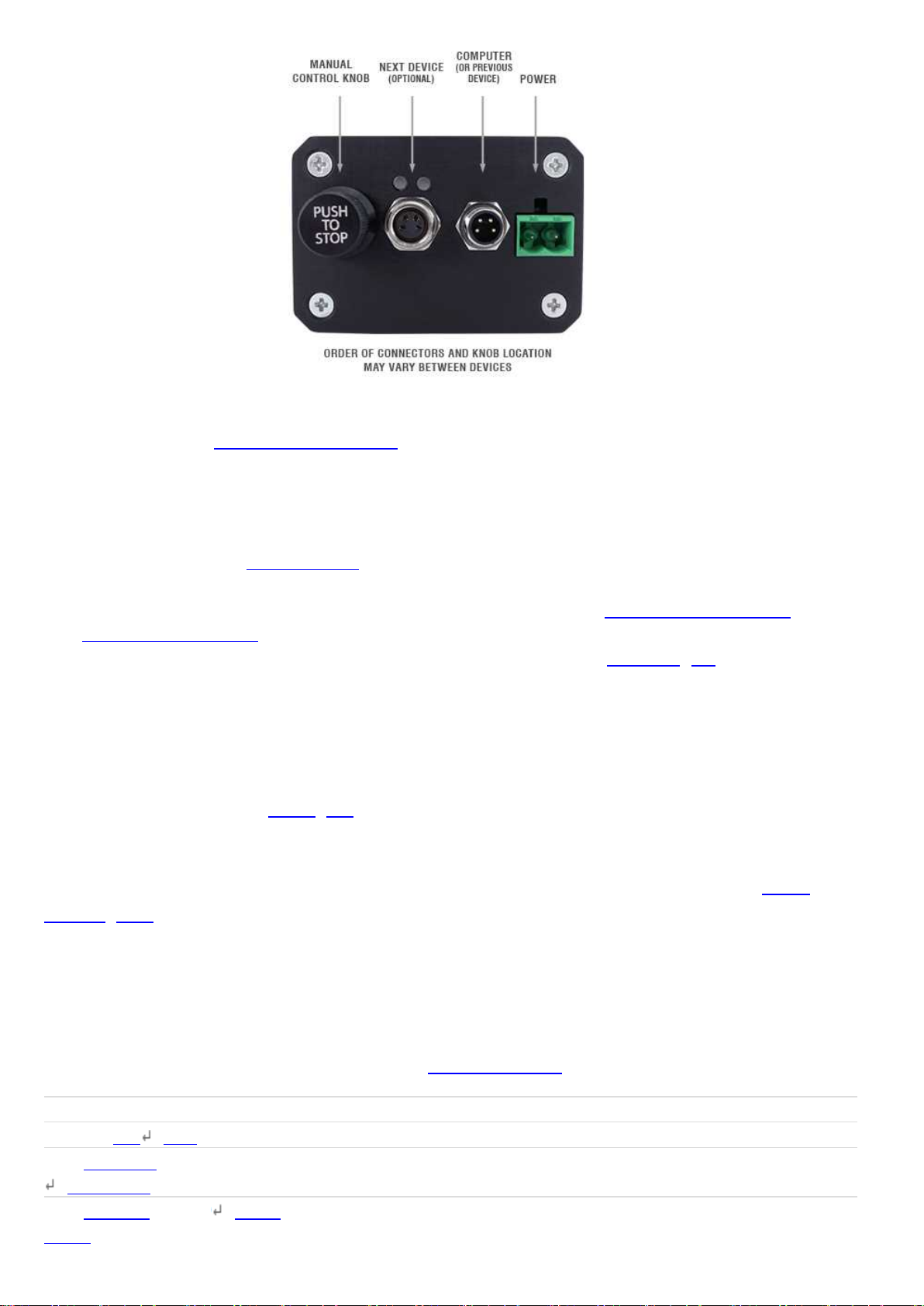
Summary of knob functionality
Turning the knob:
Moves the device in the direction of knob turn.
Pressing the knob:
Decelerates and stops the device (identical to a stop (T:23) command).
Instantly stops the device, if the device is already decelerating.
Warning: Stopping instantly may result in damage to the product and reduced lifespan. Use sparingly if
the axis is under heavy load.
Pressing and holding the knob for 1 second:
Toggles between Velocity Mode and Displacement Mode.
Trajectory Control and Behaviour
This section describes the behaviour of the device trajectory when a movement command is issued.
Software Position Limits
The travel range of the device is limited by the Minimum Position and Maximum Position settings.
The factory settings for the devices are configured to match the physical travel range. If a customized

range is desired, it can be changed by configuring the limit.min (T:106) and limit.max (T:44) settings
to appropriate values. For the Current Position, query pos (T:60).
Minimum Position
When the Current Position is less than the Minimum Position value, the device cannot move in the
negative direction(towards the motor).
Maximum Position
When the Current Position is greater than the Maximum Position value, the device cannot move in the
positive direction(towards the motor).
Movement Speed
The movement speed of the device depends on device status and various speed settings. If the
device has not been initialized by the home (T:1) command or by moving towards the home end of
the device, movement speed will be constrained to fail-safe values. The home status of the device
can be determined by reading the limit.home.triggered(T:53:103) setting.
Movement speed of the device is specified below:
move vel (T:22)
The device will move at the specified speed regardless of home status.
Knob movement in Velocity Mode
The device will move at the specified speed regardless of home status.
The speed is specified by the knob.speedprofile (T:112) and knob.maxspeed (T:111) settings.
Other movement commands - when the device has not been homed
The device will move at the slower of the maxspeed (T:42) and limit.approach.maxspeed (T:41)
settings.
Other movement commands - when the device has been homed
The device will move at the speed specified by the maxspeed (T:42) setting.
Troubleshooting X-Series Motion Devices
The following sections contain tips for troubleshooting common problems. If the device is unable to
communicate, and it is operating erratically, a manual factory reset can be performed on most
devices using the following steps. Note that this will reset most settings.
1. Power Off the device
2. Push and hold the knob for the first Axis (if applicable)
3. Power On the device
4. Continue to hold the knob in until the blue LED is lit (~5 seconds), then release.
The device has been returned to its factory defaults and can be configured as per the steps in Initial
Setup.
Front Panel Indicators
Green LED on.
The device is powered on and is operating normally.
Green LED Fades In and Out.
The device is parked.

Issue a tools parking unpark(T:65:0) command, or home (T:1) the device.
Green LED flashes slowly.
The operating conditions of the device are outside of the recommended range.
This will occur when the supply voltage is either over or under the recommended range or the
controller temperature has exceeded the set limit. Check the following:
The input voltage is within the operational range of the device. This can be read from the
device with the get system.voltage command.
The device temperature is within range. This can be read from the device with the get
system.temperature command.
Green LED off.
The device is not powered.
Check the supply connections and power adaptor for correct operation.
Red LED on or flashing.
A critical error has occurred.
Please contact Zaber Technical Support.
Yellow LED always off or flashes but no reply.
There are communication errors.
Please see the Communication Errors section below.
Blue LED flashing during a move or blinking every two seconds.
The device has slipped or stalled.
Please see the Slipping and Stalling section below.
Blue LED showing a burst of 2 flashes every 1 second.
A stationary device has been forced out of position.
Blue LED showing a burst of 5 flashes every 2 seconds.
The encoder has encountered a read error.
Please contact Zaber Technical Support.
Blue LED blinking twice per second. Device does not move.
Driver may be disabled due to over-temperature, out-of-range voltage or other driver fault; or due to
user request.
See Fx Warning Flags.
Once the issue has been resolved, send driver enable.
Manual Control
Turning the knob either way results in no movement.
The knob may have been disabled.
Check that the knob.enable (T:107) setting is correct.
Restore the default parameters through the system restore (T:36) command.
The device won't cover the full range of travel.
The device hasn't been homed.
Turn the knob anti-clockwise until the device reaches the fully retracted position. The device will
home and the full range of travel available.
Unexpected Behaviour
The device doesn't respond to a move command.
The device may need to be homed before use.
Send the home (T:1) command.
The device is moving on its own and running against the ends of travel.
The position encoder has de-synchronized.
Reset the device by power cycling it or sending the system reset (T:0) command, then re-initialize it
with the home (T:1) command.
The device is moving very slowly. It used to move faster.

The speed settings may have been changed inadvertently.
Send a system restore (T:36) command.
The device makes louder than normal noise during travel and is frequently slipping.
This condition happens if the thrust needed is more than the thrust available from the device.
Check the following:
The force on the device is less than the maximum thrust.
The voltage matches the specified voltage. Read the voltage using the get
system.voltage command. Voltage less than the specified voltage for the device will reduce the
device’s maximum thrust.
Test the following:
Try a slower target velocity. Stepper motors produce more thrust when moving slowly.
Try a lower acceleration and deceleration.
Clean the screw and lightly re-grease it with a grease that does not degrade plastics.
The device has repeatability errors smaller than 4 full steps.
If steps aren't being skipped, friction or loose parts may still cause some variation when returning to a
position.
Please contact Zaber Technical Support.
The device doesn't cover the full range of travel, or runs into the end.
A setting might have been inadvertently changed.
home (T:1) the device to see if this corrects the behaviour.
Send a system restore (T:36) command.
The device's motor unexpectedly shuts off. An Fx warning flag is present.
The motor over-temperature protection switch has been tripped. This sensor will trip if the device's
maximum continuous thrust specification is exceeded for too long. To prevent this condition from
occurring again, reduce the average force that the motor outputs by reducing acceleration, reducing
the load, or lowering the duty cycle.
Send a driver enable command. The device does not require homing.
Communication Errors
There is no communication with the device; the Yellow LED does not come on or flash.
There are several things that should be checked:
Make sure the correct serial port is selected. Try selecting other serial ports in the software.
Check the baud rate, hand shaking, parity, stop bit, etc. when configuring the serial
communications software. The required settings are listed in the RS-232
Communications section above.
Make sure there are no bent pins in the ends of all the data cables
Make sure the device is powered. The Green LED should be on.
If the computer is a laptop running on batteries, try plugging in the power. Some laptops disable
the serial ports when running on batteries.
Make sure a null modem adaptor or cable is not being used.
Make sure the correct adaptors(if any) are being used. Refer to the pinouts in the RS-232
Communications section above.
If the problem was encountered when trying to control the device with custom software, try
using one of the demo programs from the Zaber website to verify that the hardware is
functioning properly.
Two or more devices both respond to commands sent to device 1.
Most devices are shipped with their device number set as 1. If you connect the devices through Zaber
Console, you will be prompted to renumber them. If you aren't able to install and open Zaber Console,
send the renumber (T:2) command in the software you are using to set all of the device numbers to
different values.

The Yellow LED comes on briefly when sending a command, but the device does not move and does not
reply.
Check baud rate, hand shaking, parity, stop bit, etc. are set as per the RS-232
Communications defaults.
The device numbers may not be what is expected, issue a renumber (T:2) command. Make sure that
the computer does not transmit anything else while the devices renumber.
If using the Binary Protocol, check the following:
6 bytes are transmitted and that the device number and command are valid.
The software does not transmit any control characters such as line feed and spaces.
That the serial port is not configured with a termination character (it often defaults to
linefeed).
If problems are encountered when using custom software, try using one of the demo programs from
the Zaber website to verify that the hardware works.
The device does not behave as expected when software sends it a series of commands.
The computer might be set to Unicode. This is common for languages that use non-Latin based
characters. Go to Control Panel/Regional and Language Options/Advanced. Select a language for
non-unicode programs. This should be English or another Latin based character language.
Check what is being sent out of the serial port. stackoverflow.com has a list of some tools to monitor
serial ports.
In Binary mode, the device does not send replies but otherwise works.
Auto-reply might have been disabled via T:101.
Send a system restore (T:36) command.
If the problem is encountered when trying to control the device with custom software:
Use a demo program from the Zaber website to verify that the hardware is functioning
properly.
Make sure that the receiving part of the code or commercial package is correct.
Check the serial port settings are correct.
Check connectors for bent or broken pins.
In Binary mode, the device sometimes returns fewer than 6 bytes.
This typically indicates a problem with the serial port settings. Some serial ports are set to
automatically recognize and remove specific control characters such as carriage returns when they
appear in the RS-232 receive buffer.
Check that the settings are correct and are not removing or replacing characters.
Slipping and Stalling
The device moves smoothly, but only moves for a short time then stops. The Blue LED is flashing but the
device is not actually slipping or stalling.
The internal encoder counter needs to be re-initialized. Reset the device by power cycling it or
sending system reset (T:0) command, then re-initialize it with the home (T:1) command.
Ground the device and avoid operating it under statically noisy environment.
The device makes noise but does not move. The Blue LED is flashing.
The device is stalling.
Try removing all external loads. If the device now extends and retracts normally, the problem is
excessive load. Try to reduce the load and ensure the load is less than the maximum thrust. A higher
thrust or torque can be achieved by lowering the speed of the device using the maxspeed (T:42)
setting.
If a device is stalling with no external load at default speed and acceleration settings then it requires
servicing.

Warranty and Repair
For Zaber's policies on warranty and repair, please refer to the Ordering Policies.
Standard products
Standard products are any part numbers that do not contain the suffix ENG followed by a 4 digit
number. Most, but not all, standard products are listed for sale on our website. All standard Zaber
products are backed by a one-month satisfaction guarantee. If you are not satisfied with your
purchase, we will refund your payment minus any shipping charges. Goods must be in brand new
saleable condition with no marks. Zaber products are guaranteed for one year. During this period
Zaber will repair any products with faults due to manufacturing defects, free of charge.
Custom products
Custom products are any part numbers containing the suffix ENG followed by a 4 digit number. Each
of these products has been designed for a custom application for a particular customer. Custom
products are guaranteed for one year, unless explicitly stated otherwise. During this period Zaber will
repair any products with faults due to manufacturing defects, free of charge.
How to return products
Customers with devices in need of return or repair should contact Zaber to obtain an RMA form which
must be filled out and sent back to us to receive an RMA number. The RMA form contains
instructions for packing and returning the device. The specified RMA number must be included on the
shipment to ensure timely processing.
Email Updates
If you would like to receive our periodic email newsletter including product updates and promotions,
please sign up online at www.zaber.com (news section). Newsletters typically include a promotional
offer worth at least $100.
Contact Information
Contact Zaber Technologies Inc by any of the following methods:
Phone 1-604-569-3780 (direct)
1-888-276-8033 (toll free in North America)
Fax 1-604-648-8033
Mail #2 - 605 West Kent Ave. N., Vancouver, British Columbia, Canada, V6P 6T7
Web www.zaber.com
Email Please visit our website for up to date email contact information.
The original instructions for this product are available at https://www.zaber.com/manuals/X-LRQ-
DEC.

Appendix A - Available Communications Ports
Finding Installed Serial Ports
Windows
1. Open Search or Run from the Start Menu or Taskbar, type "Device Manager" and press enter.
2. Expand the Ports (COM & LPT) category.
oIn this example there are two serial ports available (COM1 and COM15), which are both USB
adaptors.
Linux
1. Finding devices
oOpen a terminal and execute the following command:
dmesg | grep -E ttyU\?S
oThe response will be similar to the following:
[ 2.029214] serial8250: ttyS0 at I/O 0x3f8 (irq = 4) is a 16550A
[ 2.432572] 00:07: ttyS0 at I/O 0x3f8 (irq = 4) is a 16550A
[ 2.468149] 0000:00:03.3: ttyS4 at I/O 0xec98 (irq = 17) is a 16550A
[ 13.514432] usb 7-2: FTDI USB Serial Device converter now attached to ttyUSB0
oThis shows that there are 3 serial ports available: ttyS0, ttyS4 and ttyUSB0 (a USB adaptor)

2. Checking port permissions
oUsing the ports found above, execute the following command
ls -l /dev/tty{S0, S4, USB0}
oThe permissions, given below, show that a user has to be root or a member of the dialout
group to be able to access these devices
crw-rw---- 1 root dialout 4, 64 Oct 31 06:44 /dev/ttyS0
crw-rw---- 1 root dialout 4, 68 Oct 31 06:45 /dev/ttyS4
crw-rw---- 1 root dialout 188, 0 Oct 31 07:58 /dev/ttyUSB0
3. Checking group membership
groups
oThe output will be similar to the following:
adm cdrom sudo dip plugdev users lpadmin sambashare
Notice that dialout is not in the list
oA user can be added to the dialout group with the following command
sudo adduser $USER dialout
oGroup membership will not take effect until the next logon.
OSX
1. Finding devices
oOpen a terminal and execute the following command:
ls /dev/cu.*serial*
oThe response will be similar to the following:
/dev/cu.usbserial-FTB3QAET
/dev/cu.usbserial-FTEJJ1YW
oThis shows that there are two serial ports available, both of which happen to be USB adaptors.
oThere may be other devices that match this query, such as keyboards or some web cameras.
To determine which one corresponds to your USB serial cable, try repeating the command with
and without the cable connected to the computer, to see which one appears and disappears.
Product Drawings


Specifications
Specification Value Alternate Unit
Built-in Controller Yes
Encoder Type Linear quadrature encoder
Encoder Resolution 50 nm
Communication Interface RS-232
Communication Protocol Zaber ASCII (Default), Zaber Binary
Maximum Centered Load 1000 N 224.3 lb
Maximum Cantilever Load 3000 N⋅cm 4248.4 oz⋅in
Guide Type Recirculating Ball Linear Guide
Stiffness in Pitch 640 N⋅m/° 27 µrad/N⋅m
Stiffness in Roll 1850 N⋅m/° 9 µrad/N⋅m
Stiffness in Yaw 665 N⋅m/° 26 µrad/N⋅m
Maximum Current Draw 1200 mA
Power Supply 24-48 VDC
Power Plug 2-pin screw terminal
Motor Steps Per Rev 200
Motor Type Stepper (2 phase)
Motor Rated Current 2300 mA/phase
Inductance 2.8 mH/phase
Default Resolution 1/64 of a step
Data Cable Connection Locking 4-pin M8
Limit or Home Sensing Magnetic home sensor
Manual Control Indexed knob with push switch
Axes of Motion 1
LED Indicators Yes
Mounting Interface M6 and M3 threaded holes
Operating Temperature Range 0 to 50 °C
Vacuum Compatible No
RoHS Compliant Yes
CE Compliant Yes
Comparison
Part Number
Microstep Size
(Default Resolution) Travel Range
Accuracy
(unidirectional) Repeatability
X-LRQ075AL-DE51C
0.09921875 µm 75 mm (2.953 ") 10 µm (0.000394 ")
< 2.5 µm
(< 0.000098 ")
X-LRQ075BL-DE51C
0.49609375 µm 75 mm (2.953 ") 13 µm (0.000512 ")
< 3.5 µm
(< 0.000138 ")
X-LRQ075HL-DE51C
0.1953125 µm 75 mm (2.953 ") 13 µm (0.000512 ")
< 3 µm
(< 0.000118 ")
X-LRQ150AL-DE51C
0.09921875 µm 150 mm (5.905 ")
10 µm (0.000394 ")
< 2.5 µm
(< 0.000098 ")
X-LRQ150BL-DE51C
0.49609375 µm 150 mm (5.905 ")
13 µm (0.000512 ")
< 3.5 µm
(< 0.000138 ")
X-LRQ150HL-DE51C
0.1953125 µm 150 mm (5.905 ")
13 µm (0.000512 ")
< 3 µm
(< 0.000118 ")

Part Number
Microstep Size
(Default Resolution) Travel Range
Accuracy
(unidirectional) Repeatability
X-LRQ300AL-DE51C
0.09921875 µm 300 mm
(11.811 ")
10 µm (0.000394 ")
< 2.5 µm
(< 0.000098 ")
X-LRQ300BL-DE51C
0.49609375 µm 300 mm
(11.811 ")
13 µm (0.000512 ")
< 3.5 µm
(< 0.000138 ")
X-LRQ300HL-DE51C
0.1953125 µm 300 mm
(11.811 ")
13 µm (0.000512 ")
< 3 µm
(< 0.000118 ")
X-LRQ450AL-DE51C
0.09921875 µm 450 mm
(17.716 ")
10 µm (0.000394 ")
< 2.5 µm
(< 0.000098 ")
X-LRQ450BL-DE51C
0.49609375 µm 450 mm
(17.716 ")
13 µm (0.000512 ")
< 3.5 µm
(< 0.000138 ")
X-LRQ450HL-DE51C
0.1953125 µm 450 mm
(17.716 ")
13 µm (0.000512 ")
< 3 µm
(< 0.000118 ")
X-LRQ600AL-DE51C
0.09921875 µm 600 mm
(23.622 ")
10 µm (0.000394 ")
< 2.5 µm
(< 0.000098 ")
X-LRQ600BL-DE51C
0.49609375 µm 600 mm
(23.622 ")
13 µm (0.000512 ")
< 3.5 µm
(< 0.000138 ")
X-LRQ600HL-DE51C
0.1953125 µm 600 mm
(23.622 ")
13 µm (0.000512 ")
< 3 µm
(< 0.000118 ")
X-LRQ075AP-DE51C
0.09921875 µm 75 mm (2.953 ") 10 µm (0.000394 ")
< 2.5 µm
(< 0.000098 ")
X-LRQ075BP-DE51C
0.49609375 µm 75 mm (2.953 ") 13 µm (0.000512 ")
< 3.5 µm
(< 0.000138 ")
X-LRQ075HP-DE51C
0.1953125 µm 75 mm (2.953 ") 13 µm (0.000512 ")
< 3 µm
(< 0.000118 ")
X-LRQ150AP-DE51C
0.09921875 µm 150 mm (5.905 ")
10 µm (0.000394 ")
< 2.5 µm
(< 0.000098 ")
X-LRQ150BP-DE51C
0.49609375 µm 150 mm (5.905 ")
13 µm (0.000512 ")
< 3.5 µm
(< 0.000138 ")
X-LRQ150HP-DE51C
0.1953125 µm 150 mm (5.905 ")
13 µm (0.000512 ")
< 3 µm
(< 0.000118 ")
X-LRQ300AP-DE51C
0.09921875 µm 300 mm
(11.811 ")
10 µm (0.000394 ")
< 2.5 µm
(< 0.000098 ")
X-LRQ300BP-DE51C
0.49609375 µm 300 mm
(11.811 ")
13 µm (0.000512 ")
< 3.5 µm
(< 0.000138 ")
X-LRQ300HP-DE51C
0.1953125 µm 300 mm
(11.811 ")
13 µm (0.000512 ")
< 3 µm
(< 0.000118 ")
X-LRQ450AP-DE51C
0.09921875 µm 450 mm
(17.716 ")
10 µm (0.000394 ")
< 2.5 µm
(< 0.000098 ")
X-LRQ450BP-DE51C
0.49609375 µm 450 mm
(17.716 ")
13 µm (0.000512 ")
< 3.5 µm
(< 0.000138 ")
X-LRQ450HP-DE51C
0.1953125 µm 450 mm
(17.716 ")
13 µm (0.000512 ")
< 3 µm
(< 0.000118 ")
X-LRQ600AP-DE51C
0.09921875 µm 600 mm
(23.622 ")
10 µm (0.000394 ")
< 2.5 µm
(< 0.000098 ")
X-LRQ600BP-DE51C
0.49609375 µm 600 mm
(23.622 ")
13 µm (0.000512 ")
< 3.5 µm
(< 0.000138 ")
Table of contents
Other Zaber Industrial Equipment manuals
Popular Industrial Equipment manuals by other brands

Barco
Barco Event Master E2 Safety guide

Alpha Technologies
Alpha Technologies Cordex 24-3.1kW Installation & operation manual

Samoa
Samoa LARIUS PNEUMATIC HOIST 30 operating instructions

Lescha
Lescha LZ Series Original instructions

Eaton
Eaton C22-PVT P Series Instruction leaflet

Honeywell
Honeywell Farenhyt Series Product installation document

Triton
Triton ARGO FT user manual

ABB
ABB HT607855 Operation manual

Smipack
Smipack BP700 Use and maintenance manual

Endura
Endura 3911A02 Installation, use & care manual

Endress+Hauser
Endress+Hauser Liquiline System CA80PH Brief operating instructions

Scraper Systems
Scraper Systems FleetPlow 440T Portable owner's manual