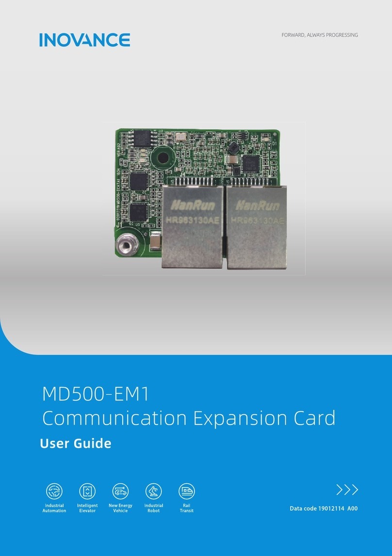
Inovance MD500-EN1 User manual

Date code 19011561 A00
User Guide
Expansion Card
MD500-EN1 Communication

Preface
- 1 -
Preface
■Introduction
MD500 series Ethernet/IP communication card (hereinafter referred to as MD500-EN1
card) is an adapter card for Ethernet/IP eldbus. It complies with international Ethernet/
IP bus standards and features high eciency, exible topology, and easy operation.
This user guide describes the specications, dimensions, installation, wiring,
communication protocols, communication-related parameters, and communication
examples of the MD500-EN1 expansion card.
■Revision history
Date Version Revision
August 2021 A00
◆First release
■Document acquisition
This user guide is not delivered along with the product. You can obtain the PDF version
of this document by the following method:
Log in to Inovance's ocial website (http://en.inovance.cn/), choose Support >
Download, search for keywords, and then download the PDF le.

Contents
- 2 -
Contents
Preface ..........................................................................................................................................1
Safety Instructions .......................................................................................................................3
Safety Precautions .................................................................................................................3
Safety Levels and Denitions ...............................................................................................3
Safety Instructions .................................................................................................................3
Safety Signs ............................................................................................................................8
1 Product Information .................................................................................................................9
1.1 Applicable AC drive ..........................................................................................................9
1.2 Introduction .....................................................................................................................9
1.3 Appearance and Dimensions ..........................................................................................9
1.4 Interface Layout and Description .................................................................................10
2 Installation and Wiring ............................................................................................................12
2.1 Installation .....................................................................................................................12
2.2 Wiring ..............................................................................................................................13
2.2.1 Ethernet/IP Topology................................................................................................... 13
2.2.2 EMC Wiring .................................................................................................................... 14
3 Ethernet/IP Communication Protocol ...................................................................................15
3.1 Description of I/O Messages Data ................................................................................15
3.2 Description of Data Transmitted by the Master ...........................................................15
3.3 Description of Data Responded to by the AC Drive .....................................................16
4 Parameters Related to Communication ................................................................................17
4.1 Communication Card Type Setting .............................................................................17
4.2 IP Address Setting of MD500-EN1 Card ........................................................................17
4.3 Parameters of AC Drive Communication Card .............................................................19
4.4 Parameter Related to Communication Control ...........................................................19
4.5 Parameters Related to Communication Monitoring ...................................................20
5 Communication Examples .....................................................................................................23
5.1 AB L16ER Controller as the Master ...............................................................................23
5.2 Inovance AM600 Controller as the Master....................................................................36
6 Troubleshooting ......................................................................................................................41

Safety Instructions
- 3 -
Safety Instructions
Safety Precautions
1) Before installing, using, and maintaining this equipment, read the safety
information and precautions thoroughly, and comply with them during operations.
2) To ensure the safety of humans and equipment, follow the signs on the equipment
and all the safety instructions in this user guide.
3) "CAUTION", "WARNING", and "DANGER" items in the manual do not indicate all
safety precautions that need to be followed; instead, they just supplement the
safety precautions.
4) Use this equipment according to the designated environment requirements.
Damage caused by improper usage is not covered by warranty.
5) Inovance shall take no responsibility for any personal injuries or property damage
caused by improper usage.
Safety Levels and Denitions
DANGER
indicates that failure to comply with the notice will result in severe
personal injuries or even death.
WARNING
indicates that failure to comply with the notice may result in severe
personal injuries or even death.
CAUTION
indicates that failure to comply with the notice may result in minor
personal injuries or damage to the equipment.
Safety Instructions
Unpacking
CAUTION
◆Check whether the packing is intact and whether there is damage, water seepage, damp,
and deformation.
◆Unpack the package by following the package sequence. Do not hit the package with
force.
◆Check whether there are damage, rust, or injuries on the surface of the equipment or
equipment accessories.
◆Check whether the number of packing materials is consistent with the packing list.

Safety Instructions
- 4 -
WARNING
◆Do not install the equipment if you nd damage, rust, or indications of use on the
equipment or accessories.
◆Do not install the equipment if you nd water seepage, component missing or damage
upon unpacking.
◆Do not install the equipment if you nd the packing list does not conform to the
equipment you received.
Storage and Transportation
CAUTION
◆Store and transport this equipment based on the storage and transportation
requirements for humidity and temperature.
◆Avoid transporting the equipment in environments such as water splashing, rain, direct
sunlight, strong electric eld, strong magnetic eld, and strong vibration.
◆Avoid storing this equipment for more than three months. Long-term storage requires
stricter protection and necessary inspections.
◆Pack the equipment strictly before transportation. Use a sealed box for long-distance
transportation.
◆Never transport this equipment with other equipment or materials that may harm or
have negative impacts on this equipment.
WARNING
◆Use professional loading and unloading equipment to carry large-scale or heavy
equipment.
◆When carrying this equipment with bare hands, hold the equipment casing rmly with
care to prevent parts falling. Failure to comply may result in personal injuries.
◆Handle the equipment with care during transportation and mind your step to prevent
personal injuries or equipment damage.
◆Never stand or stay below the equipment when the equipment is lifted by hoisting
equipment.
Installation
WARNING
◆Thoroughly read the safety instructions and user guide before installation.
◆Do not modify this equipment.
◆Do not rotate the equipment components or loosen xed bolts (especially those marked
in red) on equipment components.
◆Do not install this equipment in places with strong electric or magnetic elds.
◆When this equipment is installed in a cabinet or nal equipment, protection measures
such as a reproof enclosure, electrical enclosure, or mechanical enclosure must be
provided. The IP rating must meet IEC standards and local laws and regulations.

Safety Instructions
- 5 -
DANGER
◆Equipment installation, wiring, maintenance, inspection, or parts replacement must be
performed by only professionals.
◆Installation, wiring, maintenance, inspection, or parts replacement must be performed
by only experienced personnel who have been trained with necessary electrical
information.
◆Installation personnel must be familiar with equipment installation requirements and
relevant technical materials.
◆Before installing equipment with strong electromagnetic interference, such as a
transformer, install an electromagnetic shielding device for this equipment to prevent
malfunctions.
Wiring
DANGER
◆Equipment installation, wiring, maintenance, inspection, or parts replacement must be
performed by only professionals.
◆Never perform wiring at power-on. Failure to comply will result in an electric shock.
◆Before wiring, cut o all equipment power supplies. Wait at least 10 minutes before
further operations because residual voltage exists after power-o.
◆Make sure that the equipment is well grounded. Failure to comply will result in an
electric shock.
◆During wiring, follow the proper electrostatic discharge (ESD) procedures, and wear
an antistatic wrist strap. Failure to comply will result in damage to internal equipment
circuits.
WARNING
◆Never connect the power cable to output terminals of the equipment. Failure to comply
may cause equipment damage or even a re.
◆When connecting a drive with the motor, make sure that the phase sequences of the
drive and motor terminals are consistent to prevent reverse motor rotation.
◆Wiring cables must meet diameter and shielding requirements. The shielding layer of the
shielded cable must be reliably grounded at one end.
◆After wiring, make sure that no screws are fallen and cables are exposed in the
equipment.
Power-on

Safety Instructions
- 6 -
DANGER
◆Before power-on, make sure that the equipment is installed properly with reliable wiring
and the motor can be restarted.
◆Before power-on, make sure that the power supply meets equipment requirements to
prevent equipment damage or even a re.
◆At power-on, unexpected operations may be triggered on the equipment. Therefore, stay
away from the equipment.
◆After power-on, do not open the cabinet door and protective cover of the equipment.
Failure to comply will result in an electric shock.
◆Do not touch any wiring terminals at power-on. Failure to comply will result in an electric
shock.
◆Do not remove any part of the equipment at power-on. Failure to comply will result in an
electric shock.
Operation
DANGER
◆Do not touch any wiring terminals during operation. Failure to comply will result in an
electric shock.
◆Do not remove any part of the equipment during operation. Failure to comply will result
in an electric shock.
◆Do not touch the equipment shell, fan, or resistor for temperature detection. Failure to
comply will result in heat injuries.
◆Signal detection must be performed by only professionals during operation. Failure to
comply will result in personal injuries or equipment damage.
WARNING
◆Prevent metal or other objects from falling into the device during operation. Failure to
comply may result in equipment damage.
◆Do not start or stop the equipment using the contactor. Failure to comply may result in
equipment damage.
Maintenance
DANGER
◆Equipment installation, wiring, maintenance, inspection, or parts replacement must be
performed by only professionals.
◆Do not maintain the equipment at power-on. Failure to comply will result in an electric
shock.
◆Before maintenance, cut o all equipment power supplies and wait at least 10 minutes.
WARNING
◆Perform daily and periodic inspection and maintenance for the equipment according to
maintenance requirements and keep a maintenance record.

Safety Instructions
- 7 -
Repair
DANGER
◆Equipment installation, wiring, maintenance, inspection, or parts replacement must be
performed by only professionals.
◆Do not repair the equipment at power-on. Failure to comply will result in an electric
shock.
◆Before inspection and repair, cut o all equipment power supplies and wait at least 10
minutes.
WARNING
◆Require for repair services according to the product warranty agreement.
◆When the equipment is faulty or damaged, require professionals to perform
troubleshooting and repair by following repair instructions and keep a repair record.
◆Replace quick-wear parts of the equipment according to the replacement guide.
◆Do not operate damaged equipment. Failure to comply may result in worse damage.
◆After the equipment is replaced, perform wiring inspection and parameter settings again.
Disposal
WARNING
◆Dispose of retired equipment by following local regulations or standards. Failure to
comply may result in property damage, personal injuries, or even death.
◆Recycle retired equipment by following industry waste disposal standards to avoid
environmental pollution.

Safety Instructions
- 8 -
Safety Signs
For safe equipment operation and maintenance, comply with safety signs on the
equipment, and do not damage or remove the safety labels. The following table
describes the safety signs.
Safety Sign Description
◆Read the user guide before installation and operation.
Failure to comply will result in an electric shock.
◆Do not remove the cover at power-on or within 10 minutes
after power-o.
◆Before maintenance, inspection, and wiring, cut o input
and output power, and wait at least 10 minutes until the
power indicator is o.

1 Product Information
- 9 -
1 Product Information
1.1 Applicable AC drive
Expansion Card AC drive Remark
MD500-EN1
MD500-PLUS -
MD520 -
1.2 Introduction
MD500 series Ethernet/IP communication card (hereinafter referred to as MD500-EN1
card) is an adapter card for Ethernet/IP eldbus. It complies with international Ethernet/
IP bus standards and features high eciency, exible topology, and easy operation.
It is installed in the MD series AC drive to increase the communication eciency and
implement the AC drive networking function, which enables the AC drive to be a slave
controlled by the eld bus master.
The MD500-EN1 card software version required is 1.00 or later (check the software
version in U0-67 upon power-on after installing the card). The corresponding EDS le
name is MD500P_EIP_V1.00.eds. This user guide is applicable only for the MD500-PLUS
series AC drive. If you need to use the MD500-EN1 card with other AC drives, contact our
technical support for details.
1.3 Appearance and Dimensions
Figure 1-1 2. Appearance of the M500-EN1 card
Figure 1-2 Dimensions of the M500-EN1 card
.OVU
ħ

1 Product Information
- 10 -
1.4 Interface Layout and Description
"Figure 1-3 MD500-EN1 interface layout"shows the hardware layout of the MD500-EN1
card. The pin header J7 on the back of the MD500-EN1 card is used to connect the AC
drive. The MD500-EN1 card provides two network ports J4 and J6 for communication
with Ethernet/IP master (or other slaves). For details about the hardware, see"Table 1-1
Interface Description".
+ + +
%
%
%
%
+
Figure 1-3 MD500-EN1 interface layout
Table 1-1 Interface Description
Symbol Interface Name Function Description
J7 Pin header Used to connect the AC drive.
J4
Network port
Adopts the standard Ethernet RJ45 socket,
direction insensitive. Used for MD500-EN1 card
to establish communication with Ethernet/IP
master station(or other slave stations). Its pin
signal denitions are the same as those of the
standard Ethernet pins. They can be connected
using crossover cables or straight-through
cables.
J6
J1 EMC ground terminal Used to connect the EMC ground terminal of
the AC drive.
D13 Power indicator
(green)
Used to indicate the power status.
On: normal
O: abnormal (Check whether the installation
is correct).

1 Product Information
- 11 -
Symbol Interface Name Function Description
D1
AC drive communication
status indicator
(green)
See"Table 1-2 Description of indicators on
the MD500-EN1 card".
D4
Ethernet/IP operation
status indicator
(green)
D7 Ethernet/IP fault indicator
(red)
NOTE
◆ After the MD500-EN1 card is installed, J4 is on the left and J6 is on the
right when you face the RJ45 interface. The two interfaces are direction-
insensitive. Connect either of them to the PLC.
◆The Cat5e shielded twisted pair (STP) network cable is recommended for
operational stability.
Table 1-2 Description of indicators on the MD500-EN1 card
Indicator State Description Solution
D1 steady green Normal N/A
D1 steady o Abnormal communication
with the AC drive
Check whether FD-00 and FD-01 is set to 9
and 3 respectively.
D4 steady o
D7 steady red System fault Check the following fault codes and
solutions.
D4 steady o
D7 ashing red
Waiting for obtaining IP
address
The DHCP server assigns an IP address
to the device by using BOOTP when the
expansion card is in DHCP mode.
D4 ashing green
D7 ashing red Disconnection or timeout
Check whether the network cable is
disconnected and the master station is
running.
D4 ashing green
D7 steady o
Waiting for connecting to
the master station
Check whether the network cable
connection is normal and the master
station is running.
D4 steady green
D7 steady o Normal connection N/A

2 Installation and Wiring
- 12 -
2 Installation and Wiring
2.1 Installation
The MD500-EN1 is installed inside the MD500 series AC drive. Before installation, de-
energize the AC drive and wait about 10 minutes until the charging indicator on the AC
drive becomes o. Then, insert the MD500-EN1 card into the AC drive and fasten the
screws to avoid damage caused by external signal cable tension on the signal socket
between boards. The installation is shown in"Figure 2-1 Installation of the MD500-EN1
card".
Note that the ground terminals of both the MD500-EN1 card and AC drive must be
connected properly, as shown in"Figure 2-2 Ground terminal connection between the
MD500-EN1 card and the AC drive".
Figure 2-1 Installation of the MD500-EN1 card
Figure 2-2 Ground terminal connection between the MD500-EN1 card and the AC drive

2 Installation and Wiring
- 13 -
2.2 Wiring
2.2.1 Ethernet/IP Topology
The topological structures supported by Ethernet/IP include bus, star, and tree
topologies. Various networking can be realized by using switches correctly.
&UIFSOFU*1
.BTUFS
1 1
.%&/
4MBWF
1 1
.%&/
4MBWF
1 1
.%&/
4MBWF/
1 1
Ă
Figure 2-3 Bus topology
&UIFSOFU*1
.BTUFS
1 1
/FUXPSLTXJUDI
1 1 1 1N
.%&/
4MBWF
1 1
.%&/
4MBWF
1 1
.%&/
4MBWF/
1 1
Ă
Ă
Figure 2-4 Star topology

3 Ethernet/IP Communication Protocol
- 14 -
&UIFSOFU*1
.BTUFS
1 1
1 1 1
.%&/
4MBWF
1 1
.%&/
4MBWF
1 1
1 1 1 1 1 1
.%&/
4MBWF
1 1
.%&/
4MBWF
1 1
.%&/
4MBWF
1 1
.%&/
4MBWF
1 1
/FUXPSL
TXJUDI
/FUXPSL
TXJUDI
/FUXPSL
TXJUDI
Figure 3-3 Tree topology
2.2.2 EMC Wiring
■During on-site installation and commissioning, the signal cables and power cables
must be laid in dierent ducts. Never bundle the signal cables and power cables
together to prevent communication interference.
■Motor enclosure must be connected to PE of the AC drive. Meanwhile, the
grounding cable on the motor housing side must be connected properly. Failure to
comply will result in poor grounding eect.
■Shielded cables are recommended. Connect the shield to PE of the AC drive.

3 Ethernet/IP Communication Protocol
- 15 -
3 Ethernet/IP Communication Protocol
3.1 Description of I/O Messages Data
24 I/O Messages are available in the MD500-EN1 expansion card for data transmission,
in which 12 I/O messages transmit data from master station to slave station and another
12 I/O messages transmit data from slave station to master station.
The I/O Messages are used by the master station to modify and read AC drive data in real
time and perform periodic data exchange. Data communication addresses are directly
congured by the AC drive. The specic functions are as follows:
◆ Real-time setting of AC drive control command and target frequency
◆ Real-time reading of AC drive current state and operating frequency
◆ Function parameter and monitoring data real-time exchange between the AC drive
and Ethernet/IP master station
The I/O Messages data is used for periodic data exchange between the master station
and AC drive, as described in the following table.
I/O Messages (O->T) transmitted by the master
AC drive command AC drive target frequency Modifying function parameters of
AC drive in real time
Output I/O Messages[0] Output I/O Messages[1] Output I/O Messages[2-11]
I/O Messages (T->O) responded to by the AC Drive
AC drive state AC drive operating frequency Reading function parameters of
AC drive in real time
AC drive response I/O Messages
(T->O) Input I/O Messages[1] Input I/O Messages[2-11]
3.2 Description of Data Transmitted by the Master
For details on the data transmitted by the master, see the following table.
Description of data transmitted by the master
I/O Messages0
AC drive command word (command source set to "communication")
00: Stop as dened by F6-10 (Stop
mode)
01: Forward running
02: Reverse running
03: Forward jogging
04: Reverse jogging
05: Coast to stop
06: Stop as dened by F6-10 (Stop mode)
07: Fault reset
I/O Messages1
AC drive target frequency (frequency source set to "communication") in the
range of reverse frequency upper limit (negative value) to forward frequency
upper limit (decimal places included, for example, 2000 corresponds to 20.00
Hz on the AC drive).
When the set target frequency exceeds this range, the AC drive runs at the
frequency upper limit.

3 Ethernet/IP Communication Protocol
- 16 -
Description of data transmitted by the master
I/O Messages2 to I/
O Messages11
Used to change the function parameter values (groups F and A) in real time
without writing the values into the EEPROM. FE-02 to FE-11 correspond to I/O
Messages2 to I/O Messages11. For details about the conguration, see the I/O
Messages data conguration.
3.3 Description of Data Responded to by the AC Drive
For details on the data responded to by the AC drive, see the following table.
Description of data responded to by the AC Drive
I/O Messages0
Indicates AC drive operating frequency, which is dened by bits as
shown below:
Bit0: 0: AC drive stop; 1: AC drive running
Bit1: 0: Forward running; 1: Reverse running
Bit2: 0: No fault; 1: AC drive fault
Bit3: 0: Operating frequency not reached; 1: Operating frequency
reached
Bit4–7: Reserved
Bit 8 to Bit 15: AC drive fault code
I/O Messages1 Indicates feedback of the AC drive operating frequency (unit: 0.01 Hz),
which is a signed Int16 value.
I/O Messages2 to I/O
Messages11
Indicates function parameter values (groups F and A) and monitoring
parameter values (group U) read in real time.
FE-22 to FE-31 correspond to I/O Messages2 to I/O Messages11.
For details about the conguration, see the I/O Messages data
conguration.

4 Parameters Related to Communication
- 17 -
4 Parameters Related to Communication
4.1 Communication Card Type Setting
After powering on the AC drive, set FD-00 and FD-01 to 9 (baud rate: 115200 bps) and 3
(no check, 8-N-1) respectively to enable communication between the MD500-EN1 card
and the AC drive.
Parameter
No. Parameter Name Setting range Default Meaning
FD-00 Baud rate
0:300 bps
1: 600 bps
2:1200 bps
3:2400 bps
4:4800 bps
5:9600 bps
6:19200 bps
7:38400 bps
8:57600 bps
9:115200 bps
9
Used to set the
data transmission
rate between the
communication
expansion card
and the AC drive.
FD-01 Modbus data format
0: No check (8-N-2)
1: Even parity check (8-
E-1)
2: Odd parity check (8-
O-1)
3: No check (8-N-1)
3
Used to set
the Modbus
data format
between the
communication
expansion card
and the AC drive.
4.2 IP Address Setting of MD500-EN1 Card
Communication card parameter setting for the AC drive.
Parameter No. Parameter Name Setting Range Description
FD-37 DHCP function
selection
0: Disabled
1: Enabled
Used to set the DHCP function
of the Ethernet/IP expansion
card. Enabling the DHCP function
deactivates IP address settings,
namely parameters FD-38 to FD-
41, FD-42 to FD-45, and FD-46 to
FD-49.
FD-38 to FD-41 Expansion card IP
address 0-255 Used to set the IP address of
Ethernet/IP expansion card.

4 Parameters Related to Communication
- 18 -
Parameter No. Parameter Name Setting Range Description
FD-42 to FD-45 Subnet mask of
expansion card 0-255 Used to set subnet mask of
Ethernet/IP expansion card.
FD-46 to FD-49 Gateway address of
expansion card 0-255 Used to set gateway address of
Ethernet/IP expansion card.
IP address setting is divided into static IP and DHCP dynamic IP address. Select the IP
mode in parameter No. FD-37. Set static IP address in parameter No. FD-37 to FD-49.
For example, congure static IP address :192.168.0.6 , subnet mask:255.255.255.0, and
gateway address:192.168.0.1, set the following parameters.
Parameter No. Function Set Value
FD-37 DHCP function selection 0
FD-38 Most signicant byte of the IP address 192
FD-39
Second most signicant byte of the
IP address 168
FD-40
Third most signicant byte of the IP
address 0
FD-41 Least signicant byte of the IP address 6
FD-42
Most signicant byte of the subnet
mask 255
FD-43
Second most signicant byte of the
subnet mask 255
FD-44
Third most significant byte of the
subnet mask 255
FD-45
Least signicant byte of the subnet
mask 0
FD-46 Most signicant byte of the gateway 192
FD-47
Second most signicant byte of the
gateway 168
FD-48
Third most signicant byte of the
gateway 0
FD-49 Least signicant byte of the gateway 1
View MAC address when DHCP/BOOTP function is used. To view the MAC address,
read the label attached to the expansion card or check the related parameter (see "4.3
Parameters of AC Drive Communication Card" for details).
This card supports IP address conict detection. When other devices in the network
share the same IP address with the expansion card, D7 indicator will be steady ON and
bit2 of FD-58 will be changed to 1.
The following three cases are present in IP address conict detection.

4 Parameters Related to Communication
- 19 -
No. Case Symptom Solution
1
Both devices support IP
address conict detection. The
two devices are powered on
one after another.
The device powered on rst
uses the IP address and
continues to operate. The
device powered on later
enters the conict mode.
Check device IP address
and then modify the
repeated one.
2
Both devices support IP
address conict detection.
The two devices are powered
on at approximately the same
time.
The two devices enter the
IP address conict mode
simultaneously.
3
One device supports IP address
conict detection and the
second device does not.
Regardless of which device is
powered on rst, the device
that does not support IP
address detection uses the
IP address. The device that
supports IP address conict
detection enters the conict
mode.
NOTE
◆When the DHCP server assigns an IP address to the expansion card,
active conict detection applies. Later, passive detection applies. If
the devices are separately assigned with the same dynamic (static) IP
address on the same network, both expansion cards do not report IP
address conict.
◆When using the DHCP function to assign IP addresses, the address
assignment would fail if IP address conict occurs.
4.3 Parameters of AC Drive Communication Card
Parameter No. Parameter Name Unit Description
FD-61 The rst two bytes of expansion card
MAC address 1Expansion card MAC
address
FD-62 The middle two bytes of expansion
card MAC address 1Expansion card MAC
address
FD-63 The last two bytes of expansion card
MAC address 1Expansion card MAC
address
FD-58 Expansion card error code 1Expansion card error
code
4.4 Parameter Related to Communication Control
Parameter
No. Name Setting Range Decimal
Address
U3-16 Frequency
setting
-Maximum frequency to +Maximum frequency
0.01 Hz 29456
Table of contents
Other Inovance Computer Hardware manuals
Popular Computer Hardware manuals by other brands

IEI Technology
IEI Technology WSB-9454 Quick installation guide

Omron
Omron CP1L CPU UNIT - 03-2009 Operation manual

EK-Quantum
EK-Quantum Vector FTW3 RTX 3080 user guide

Cisco
Cisco Aironet 350 Series quick start guide

Renesas
Renesas R0E33062PMSRC0 user manual

Dynisco
Dynisco UPR700 Installation and operation manual