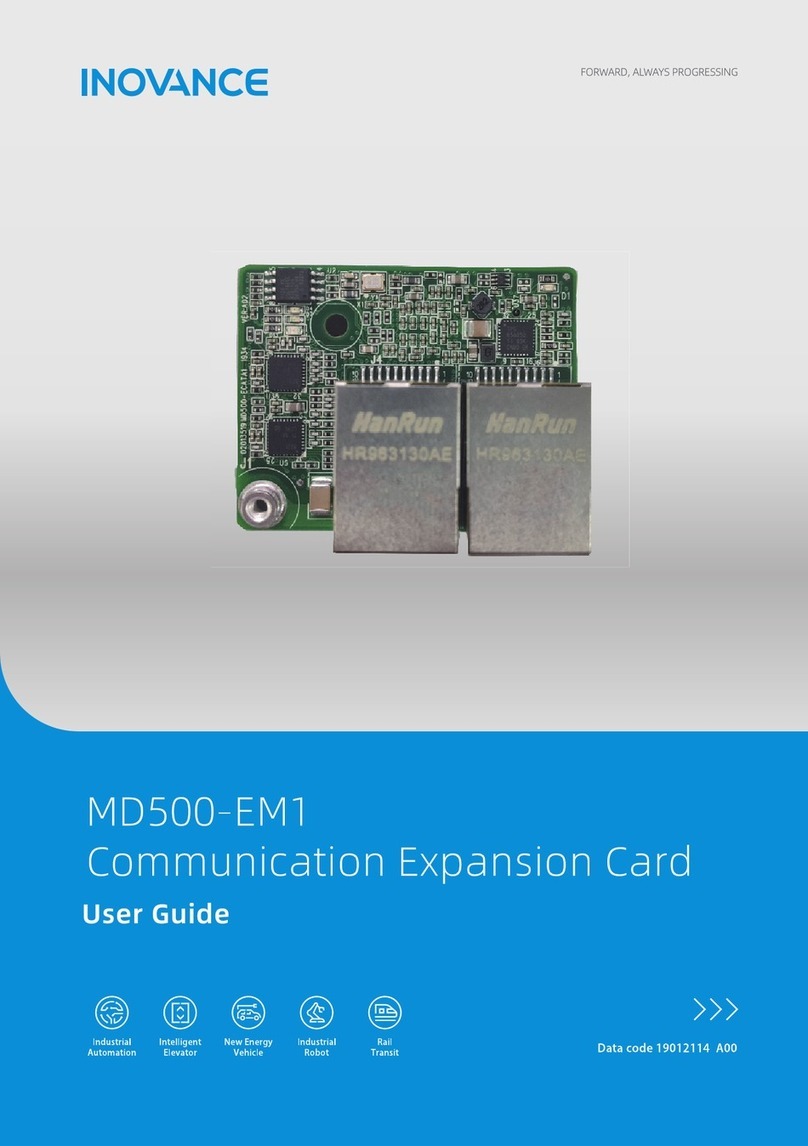
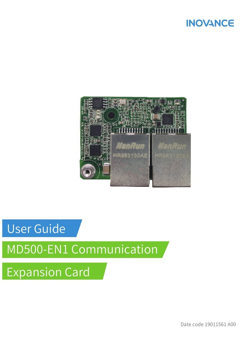
Inovance MD520IO1 User manual

*19012215A00*


‑1‑
Preface
■ Introduction
The MD520IO1 card is an I/O expansion card applies to AC drives. The card supports
three DI circuits, one AO circuit, one RO circuit, and one isolated RS‑485 circuit.
This guide describes the technical specifications, dimensions, installation, wiring, and
troubleshooting of the MD520IO1 expansion card.
■ Revision history
Date Version Description
April 2023 A00 First release
■ Document acquisition
This guide is not delivered along with the product. You can download the PDF version
by the following way:
Log in to Inovance's website (
www.inovance.com
), choose Support > Download,
search by keyword, and then download the PDF file.
■ Warranty
If your product becomes defective under normal use conditions, we will offer
guaranteed repair services within the warranty period. You will be charged for any
repair work after the warranty period expires.
The warranty does not cover any damage caused by:
●The user does not perform operations in compliance with the user manual of the
product.
●The product is damaged due to fire, flood, and abnormal voltage.
●The user uses the product for abnormal functions.
●The user uses the product outside the specified specification range.
●The product is damaged by force majeure, such as natural disasters, earthquakes,
or lightning strikes.
The maintenance fee is charged according to the latest Price List of Inovance. If
otherwise agreed upon, the agreed terms and conditions shall prevail.

‑2‑
TTaabbllee ooff CCoonntteennttss
Preface. . . . . . . . . . . . . . . . . . . . . . . . . . . . . . . . . . . . . . . . . . . . . . . . . . . . . . . . . . . . . 1
1 Product Information . . . . . . . . . . . . . . . . . . . . . . . . . . . . . . . . . . . . . . . . . . . . . . . 3
1.1 Introduction . . . . . . . . . . . . . . . . . . . . . . . . . . . . . . . . . . . . . . . . . . . . . . . . . 3
1.2 Applicable AC Drive . . . . . . . . . . . . . . . . . . . . . . . . . . . . . . . . . . . . . . . . . . . 6
1.3 Technical Specifications. . . . . . . . . . . . . . . . . . . . . . . . . . . . . . . . . . . . . . . 7
1.4 Outline Dimensions . . . . . . . . . . . . . . . . . . . . . . . . . . . . . . . . . . . . . . . . . . 10
1.5 Terminal Descriptions. . . . . . . . . . . . . . . . . . . . . . . . . . . . . . . . . . . . . . . . 10
2 Installation and Wiring . . . . . . . . . . . . . . . . . . . . . . . . . . . . . . . . . . . . . . . . . . . . 13
2.1 Installation. . . . . . . . . . . . . . . . . . . . . . . . . . . . . . . . . . . . . . . . . . . . . . . . . . 13
2.2 Wiring . . . . . . . . . . . . . . . . . . . . . . . . . . . . . . . . . . . . . . . . . . . . . . . . . . . . . . 14
2.2.1 Wiring Instructions . . . . . . . . . . . . . . . . . . . . . . . . . . . . . . . . . . . . . . . 14
2.2.2 EMC Routing Instructions . . . . . . . . . . . . . . . . . . . . . . . . . . . . . . . . . 18
3 Troubleshooting. . . . . . . . . . . . . . . . . . . . . . . . . . . . . . . . . . . . . . . . . . . . . . . . . . 20

‑3‑
1 Product Information
1.1 Introduction
The MD520IO1 card is an I/O expansion card applied to the AC drive. The card
supports three DI circuits, one AO circuit, one RO circuit, and one isolated RS‑485
circuit.
Figure 1‑1 MD520IO1 card appearance
The following table describes differences among the MD520IO1 card, MD38IO1 card,
MD38IO2 card, and MD38IO3 card.

‑4‑
Type MD520IO1 MD38IO1 MD38IO2 MD38IO3
External
power
supply
Not
supported
External power
supply: +24V‑COM
Digital input power
supply: OP1
External power
supply: +24V‑COM
Digital input power
supply: OP2
Not supported
AI Not
supported
AI3‑PGND
●Optocoupler
isolation input,
differential
voltage input,
temperature
detection resistor
input
●Input voltage
range: ‑10 VDC to
+10 VDC
●PT100 and
PT1000
temperature
sensors
●The input mode
is determined by
DIP switch S1.
Only one function
is available at a
time.
Not supported Not supported

‑5‑
Type MD520IO1 MD38IO1 MD38IO2 MD38IO3
DI
Three
channels: DI6
to DI8
Refer to DI
technical
specifications.
Five channels: DI6
to DI10
Optocoupler
isolation,
compatible with
bipolarity input
Input impedance:
2.4 kΩ
Voltage at level
input: 9 V to 30 V
Three channels:
DI6 to DI8
Optocoupler
isolation,
compatible with
bipolarity input
Input impedance:
3.3 kΩ for DI6 and
DI7 and 2.4 kΩ for
DI8
Voltage range upon
level input: 9 V to
30 V
DI6, DI7 and DI8:
Common input
terminals with the
input frequency
less than 100 Hz
Three channels:
DI6 to DI8
Optocoupler
isolation,
compatible with
bipolarity input,
maximum input
frequency of 100
Hz
Input impedance:
3.4 kΩ
Voltage range upon
level input: 9 V to
24 V
AO
AO2
Refer to AO2
technical
specifications.
AO2‑GND
Output voltage: 0 V
to 10 V
Output current: 0
mA to 20 mA
Impedance for
output current: 0 Ω
to 500 Ω
Not supported Not supported
DO Not
supported
DO2‑CME
Optocoupler
isolation, bipolarity
open collector
output
Output voltage
range: 0 V to 24 V
Output current
range: 0 mA to 50
mA
Not supported Not supported

‑6‑
Type MD520IO1 MD38IO1 MD38IO2 MD38IO3
Relay
output
NO terminal
1: PA‑PC
NC terminal: PA‑PB
NO terminal: PA‑PC
Contact driving
capacity: 250 VAC,
3 A, COSφ = 0.4; 30
VDC, 1 A
Not supported
NO terminal: PA‑PC
Contact drive
capability: 250 VAC,
5 A; 30 VDC, 5 A
RS‑485
communi‑
cation
Supported Supported Not supported Supported
CAN
communi‑
cation
Not
supported Supported Not supported Not supported
1.2 Applicable AC Drive
Expansion Card
Model Applicable AC Drive
MD520IO1
MD290
MD480 (for T2 models and above)
MD480‑PLUS
MD500
MD500E
MD480‑PLUS
MD510
MD520
Note
Except the AO2 of the MD520IO1 card, the MD480‑PLUS series and MD500‑PLUS series
AC drives support other terminal functions of the MD520IO1 card.

‑7‑
1.3 Technical Specifications
For details on the layout of the interfaces on the MD520IO1 card, see “
Figure 1–3
”
on
page 10
.
■ Technical specifications of the power supply terminal J1
The power supply terminal J1 is located on the back of the expansion card and
supplies power only to the card.
Name Ground Technical Specification
+5V GND
●Standard voltage: +5 V
●Voltage fluctuation range: ±5%
●Maximum input current: 0.8 A
+15V GND
●Standard voltage: +15 V
●Voltage fluctuation range: ±10%
●Maximum input current: 0.09 A
‑15V GND
●Standard voltage: ‑15 V
●Voltage fluctuation range: ±10%
●Maximum input current: 0.09 A
+24V COM
●Standard voltage: +24V
●Voltage fluctuation range: ±10%
●Maximum input current: 0.47 A
■ Technical specifications of the DI
Signal
Name Technical Specification Remarks
DI6 Isolated sink/source programmable DI; input frequency: < 100
Hz; operating voltage range: 9 V to 30 V; invalid voltage: < 5 V;
valid voltage: > 15 V; input impedance: 3.61 kΩ
Optocou‑
pler
isolation
DI7
DI8

‑8‑
■ Technical specifications of the AO
Signal
Name Technical Specification
AO2
●Voltage range: 0 V to 10 V
●Maximum output current: 0 mA to 20 mA
●Resolution: 12‑bit
●Accuracy (25°C): ±2%
●Cut‑off frequency: 115.5 Hz
●Isolation: Not required
●Type of protection: Clamp diode
●In the voltage mode, the maximum output load current is 2 mA and the load
impedance is larger than 5 kΩ. In the current mode, the load impedance is
lower than 500 Ω.
■ Technical specifications of the RS-485 communication terminal
Signal
Name
Technical Specification
485+ ●RS‑485 communication
●Maximum rate supported by hardware: 250 Kbps. The actual maximum rate
is subject to the software.
●Transmission distance: The maximum transmission distance of the baud
rate 9.6 Kbps is 1 km. The higher the rate, the shorter the transmission
distance.
485‑
■ Technical specifications of the relay terminal
Signal
Name
Terminal
Name
Technical Specification
PA Normally
open
(NO)
terminal
Contact capacity: 250 VAC/5 A, 30 VDC/5A
PC

‑9‑
■ Safety requirements
Electrical Clearance/Creepage Distance (unit: mm)
Isolation Circuit Insulation
Type 1
isolation
Compo‑
nent
Electrical
Clearance
Creepage
Distance
From the high‑voltage pin to the low‑
voltage pin of the relay RI Relay (K1) 6.3 6.3
Note
●1FI: Functional insulation; BI: Basic insulation; SI: Supplementary insulation;
RI: Reinforced insulation
●If the functional insulation requirements are not met, you must
communicate with Inovance in advance.
●Board slotting requirements: ≥ 1.0 mm (error must be considered).
Determine if slotting is required based on actual situations.
●The margin is not taken into account to the above clearance/distance. If
there is sufficient space, add the margin of 0.3 mm to 0.5 mm to the listed
clearance/distance.

‑10‑
1.4 Outline Dimensions
Figure 1‑2 Outline dimensions of the MD520IO1 card (unit: mm)
1.5 Terminal Descriptions
■ Terminal layout
The following figure shows the layout of the MD520IO1 card terminal.
Figure 1‑3 MD520IO1 card terminal layout

‑11‑
■ Terminal descriptions
Symbol Name Function
CN1 PA‑PC NO terminal Contact driving capacity: 250 VAC/5 A, 30 VDC/
5A
CN2
485+
RS‑485
communication
signal (positive)
Modbus protocol supported, isolation input
485‑
RS‑485
communication
signal
(negative)
CGND
RS‑485
communication
signal ground
DI8 One digital
input
●Optocouper isolation, bipolar input
compatible, maximum input frequency of
100 Hz; external or internal power supply
selected by S2
●Input impedance: 3.61 kΩ
●Voltage range upon level input: 9 V to 30 V
CN3
DI6, DI7 Two digital
inputs
●Optocouper isolation, bipolar input
compatible, maximum input frequency of
100 Hz; external or internal power supply
selected by S2
●Input impedance: 3.61 kΩ
●Voltage range upon level input: 9 V to 30 V
AO2 One analog
output
Voltage or current output selected by S3
●Output voltage: 0 V to 10 V
●Output current: 0 mA to 20 mA
●Impedance for output current: 0 Ω to 500 Ω
GND
+5V, ±15V
power supply
and signal
reference
ground
‑

‑12‑
Symbol Name Function
S1
Selection of RS‑
485 termination
resistor
Two‑position
DIP switch
●Toggle positions 1 and 2 to ON: Termination
resistor connected
●Toggle positions 1 and 2 to OFF: Termination
resistor disconnected
●The default setting is OFF, and toggling S1 to
the left indicates OFF.
S2 DI source/sink
wiring selection Slide switch
●If the DI uses the sink wiring method,
connect OP to 24V and slide the switch to
OFF.
●If the DI uses the source wiring method,
connect OP to COM and slide the switch to
ON.
S3 AO2 output
type Slide switch
Voltage type: 0 V to 10 V
DIP switch: OFF (The default setting is OFF,
and toggling S1 upward indicates OFF.)
Current type: 0 mA to 20 mA
DIP switch: ON

‑13‑
2 Installation and Wiring
2.1 Installation
The MD520IO1 card is installed in the MD520 series AC drive. Before installation,
power off the AC drive, and wait for about 10 minutes until the charging indicator on
the AC drive becomes OFF. After inserting the MD520IO1 card into the drive, fix
corresponding screws to prevent the signal socket from being damaged by external
signal cables. “
Figure 2–1
”
on page 13
shows the installation position of the
MD520IO1 card.
Figure 2‑1 MD520IO1 card installation

‑14‑
2.2 Wiring
2.2.1 Wiring Instructions
Note
●By default, S2 is toggled to OFF and the internal 24 V power supply is
connected. When S2 is toggled to ON and OP and COM are connected, an
external power supply is required. For details, see "
DI
"
on page 16
.
●By default, S3 is in the voltage mode.
■ AO2
AO2: By default, the OFF state of the S3 DIP switch indicates the voltage mode with
the output voltage ranging from 0 V to 10 V. The ON state of the S3 DIP switch
indicates the current mode with the output current ranging from 0 mA to 20 mA.
The AO2 can be assigned with different functions, as shown in the table below. For
more information, see
MD520 Series General Purpose AC Drive Function Guide
. The
preceding figure shows the wiring for the AO2 to connect to the meter (AM).

‑15‑
Definition Value
AO2 function selection
0: Operating frequency
1: Set frequency
2: Output current
3: Output torque (absolute value)
4: Output power
5: Output voltage
6: Pulse input
7: AI1
8: AI2
9: AI3
10: Length
11: Count value
12: Communication
13: Motor speed
14: Output current
15: Bus voltage
16: Output torque (actual value)
Other value: F connector
■ RS-485 communication terminal
Use a three‑conductor shielded cable for the RS‑485 bus. The AC drive comes with
three cables for connection to the RS485+, RS485–, and CGND terminals. The two
cables to connect to the RS485+ and RS485–terminals are twisted pair cables. The
third cable is connected to the RS‑485 reference ground CGND. The shield is
connected to the equipment ground. Connect a 120 Ω termination resistor at each
end of the bus to prevent RS‑485 signal reflection. Toggle positions 1 and 2 of the S1
DIP switch on the expansion card to ON to connect the termination resistor to the
drive. The following table describes the pins of the communication cable between the
drive and PLC.

‑16‑
Table 2–1 Pins of the communication cable between the drive and PLC
AC Drive PLC
Communica‑
tion Type Signal Name Function Communica‑
tion Type Signal Name Function
RS‑485
RS485+ RS‑485 signal
(positive)
RS‑485
RS485+ RS‑485 signal
(positive)
RS485‑ RS‑485 signal
(negative) RS485‑ RS‑485 signal
(negative)
CGND
Signal
reference
ground
CGND
Signal
reference
ground
‑PE (shield
layer) Enclosure ‑ PE (shield
layer) Enclosure
■ DI
●Sink wiring
Figure 2‑2 Sink wiring
Using the internal 24 V power supply of the drive is the most commonly used
wiring method. By default, S2 is toggle to OFF. In this case, OP of the drive is
connected to the internal 24 V power supply, and COM of the drive is connected to
0V of the external controller.

‑17‑
When using the external 24 V power supply, toggle S2 to ON. Then connect +24V of
the external power supply to OP of the drive and connect 0V of the external power
supply to the corresponding DI through the contact of the controller.
Note
In the mode, the DIs of different AC drives cannot be connected in parallel. Otherwise,
the DI may malfunction. If DIs of different AC drives must be connected in parallel,
connect the anode of a diode to the DI in series and make the diode satisfy the
requirement: IF > 40 mA and VR > 40 V, as shown in “
Figure 2–3
”
on page 17
.
The MD520 series AC drive is as an example, as shown in “
Figure 2–3
”
on page 17
.
Figure 2‑3 Parallel connection for DIs of different AC drives in sink wiring
mode
●Source wiring

‑18‑
Figure 2‑4 Source wiring
When using the source wiring method, an external 24 V power supply is required.
Toggle S2 to ON and connect 0V of the external controller to OP of the drive, as
shown in “
Figure 2–4
”
on page 18
.
2.2.2 EMC Routing Instructions
●During field installation and commissioning, the I/O signal includes the analog
output signal, the digital input signal, and the relay output signal. Route the
control circuit cables and the main circuit cables (R/S/T cables or U/V/W cables),
other power cables, or electrical powers through different routes with a distance
of at least 30 cm. Failure to comply will result in disturbed I/O signals.
●Connect the motor casing to the ground terminal (PE terminal) of the AC drive,
and connect the ground cable of the motor casing properly. Otherwise, grounding
performance will be degraded.
●It is recommended to use shielded signal cables to prevent the I/O signal circuit
from being disturbed by peripheral interference. Connect both ends of the shield
to the device in 360 degrees with the shield bracket. Use different shielded cables
for different analog signal cables and use shielded twisted pair cables for digital
signal cables. Connect the drain wire of the analog terminal shield to the PE
terminal on the drive side.
Table of contents
Other Inovance Computer Hardware manuals
Popular Computer Hardware manuals by other brands

Crest Audio
Crest Audio NC-SAC - TECHNICAL Technical data

ekwb
ekwb EK-FC R9-295X2 INSTALLATION AND MOUNTING MANUAL

BE QUIET!
BE QUIET! SILENT LOOP 2 manual

ICP vortex Corporation
ICP vortex Corporation 64-Bit PCI - Wide/Ultra2 SCSI specification

Aaeon
Aaeon NIM-S13D Quick installation guide

Intel
Intel 82496 CACHE CONTROLLER user manual