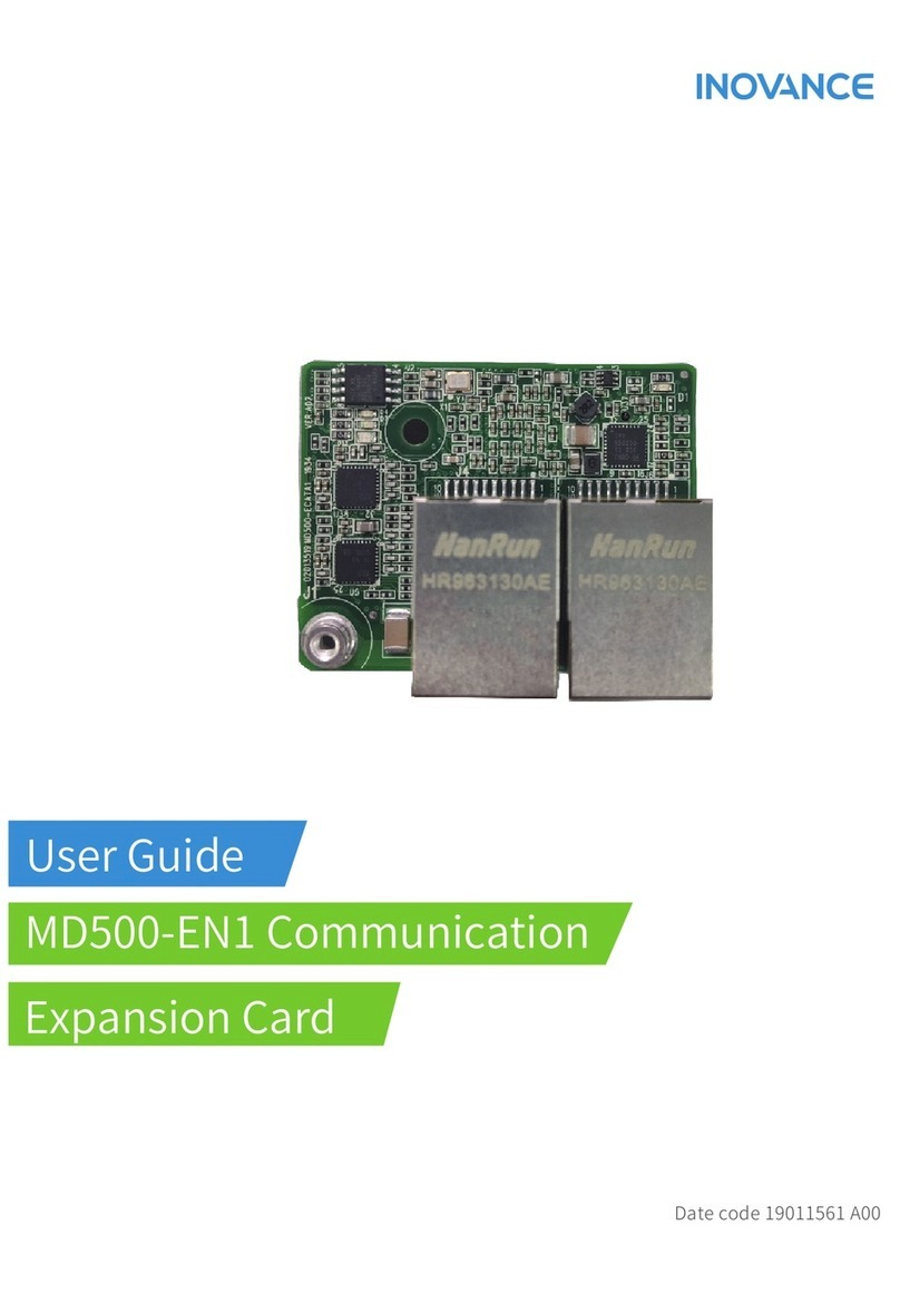
Inovance MD500-EM1 User manual


‑1‑
Preface
Preface
About This Guide
The MD500 series communication expansion cards (hereinafter MD500‑EM1 card)
conform to Modbus‑TCP protocol and feature high efficiency, flexible topology, and
easy operation.
This document gives a detailed description of the MD500‑EM1 card, including its
specifications, dimensions, installation, wiring, communication protocol,
communication parameters, and communication instances.
Revision History
Date Version Description
March 2022 A00 First release
How to Obtain
This guide is not delivered with the product. You can obtain the PDF version by the
following method:
Log in to Inovance's website (
http://en.inovance.cn/
), choose Support >Download,
search by keyword, and then download the PDF file.

‑2‑
TTaabbllee ooff CCoonntteennttss
Preface.............................................................................. 1
General Safety Instructions. . . . . . . . . . . . . . . . . . . . . . . . . . . . . . . . . . . . . . . . . . . . . . . . . . . . . . . . . . . . 3
1 Product Information . . . . . . . . . . . . . . . . . . . . . . . . . . . . . . . . . . . . . . . . . . . . . . . . . . . . . . . . . . . . . . . . 9
1.1 Applicable AC Drive . . . . . . . . . . . . . . . . . . . . . . . . . . . . . . . . . . . . . . . . . . . . . . . . . . . . . . . . . . . . 9
1.2 Product Introduction. . . . . . . . . . . . . . . . . . . . . . . . . . . . . . . . . . . . . . . . . . . . . . . . . . . . . . . . . . . 9
1.3 Appearance and Dimensions. . . . . . . . . . . . . . . . . . . . . . . . . . . . . . . . . . . . . . . . . . . . . . . . . . . . 9
1.4 Interface Layout and Description . . . . . . . . . . . . . . . . . . . . . . . . . . . . . . . . . . . . . . . . . . . . . . . 10
2 Installation and Wiring . . . . . . . . . . . . . . . . . . . . . . . . . . . . . . . . . . . . . . . . . . . . . . . . . . . . . . . . . . . . . 13
2.1 Installation. . . . . . . . . . . . . . . . . . . . . . . . . . . . . . . . . . . . . . . . . . . . . . . . . . . . . . . . . . . . . . . . . . . 13
2.2 Wiring . . . . . . . . . . . . . . . . . . . . . . . . . . . . . . . . . . . . . . . . . . . . . . . . . . . . . . . . . . . . . . . . . . . . . . . 14
2.2.1 Network topology. . . . . . . . . . . . . . . . . . . . . . . . . . . . . . . . . . . . . . . . . . . . . . . . . . . . . . . . . 14
2.2.2 EMC Wiring Instructions . . . . . . . . . . . . . . . . . . . . . . . . . . . . . . . . . . . . . . . . . . . . . . . . . . . . 15
3 Modbus‑TCP Communication Protocol. . . . . . . . . . . . . . . . . . . . . . . . . . . . . . . . . . . . . . . . . . . . . . . 16
3.1 Overview. . . . . . . . . . . . . . . . . . . . . . . . . . . . . . . . . . . . . . . . . . . . . . . . . . . . . . . . . . . . . . . . . . . . . 16
3.2 Communication Data Frame Format. . . . . . . . . . . . . . . . . . . . . . . . . . . . . . . . . . . . . . . . . . . . 16
4 Communication Parameters . . . . . . . . . . . . . . . . . . . . . . . . . . . . . . . . . . . . . . . . . . . . . . . . . . . . . . . . 19
4.1 Communication Card Type Setting for the AC Drive . . . . . . . . . . . . . . . . . . . . . . . . . . . . . . 19
4.2 IP Address Setting of MD500‑EM1 Card . . . . . . . . . . . . . . . . . . . . . . . . . . . . . . . . . . . . . . . . . . 20
4.3 Expansion Card Parameters . . . . . . . . . . . . . . . . . . . . . . . . . . . . . . . . . . . . . . . . . . . . . . . . . . . 22
4.4 Basic AC Drive Parameters. . . . . . . . . . . . . . . . . . . . . . . . . . . . . . . . . . . . . . . . . . . . . . . . . . . . . 23
4.5 Modbus‑Specific Parameter Communication Addresses . . . . . . . . . . . . . . . . . . . . . . . . . . 23
5 Communication Examples . . . . . . . . . . . . . . . . . . . . . . . . . . . . . . . . . . . . . . . . . . . . . . . . . . . . . . . . . . 32
5.1 Communication Example. . . . . . . . . . . . . . . . . . . . . . . . . . . . . . . . . . . . . . . . . . . . . . . . . . . . . . 32
6 Troubleshooting . . . . . . . . . . . . . . . . . . . . . . . . . . . . . . . . . . . . . . . . . . . . . . . . . . . . . . . . . . . . . . . . . . . 36
6.1 Troubleshooting. . . . . . . . . . . . . . . . . . . . . . . . . . . . . . . . . . . . . . . . . . . . . . . . . . . . . . . . . . . . . . 36
Table of Contents

‑3‑
General Safety Instructions
Safety Precautions
1. This chapter presents essential safety instructions for a proper use of the
equipment. Before operating the equipment, read through the guide and
comprehend all the safety instructions. Failure to comply with the safety
instructions may result in death, severe personal injuries, or equipment damage.
2. "CAUTION", "WARNING", and "DANGER" items in the guide only indicate some of
the precautions that need to be followed; they just supplement the safety
precautions.
3. Use this equipment according to the designated environment requirements.
Damage caused by improper use is not covered by warranty.
4. Inovance shall take no responsibility for any personal injuries or property damage
caused by improper usage.
Safety Levels and Definitions
Indicates that failure to comply with the notice will result in death or
severe personal injuries.
Indicates that failure to comply with the notice may result in death or
severe personal injuries.
Indicates that failure to comply with the notice may result in minor or
moderate personal injuries or equipment damage.
General Safety Instructions
●Drawings in the guide are sometimes shown without covers or protective guards.
Remember to install the covers or protective guards as specified first, and then
perform operations in accordance with the instructions.
●The drawings in the guide are shown for illustration only and may be different
from the product you purchased.
Unpacking
●Do not install the equipment if you find damage, rust, or signs of use on the equipment
or accessories upon unpacking.
●Do not install the equipment if you find water seepage or missing or damaged
components upon unpacking.
●Do not install the equipment if you find the packing list does not conform to the
equipment you received.

‑4‑
General Safety Instructions
●Check whether the packing is intact and whether there is damage, water seepage,
dampness, and deformation before unpacking.
●Unpack the package by following the unpacking sequence. Do not strike the package
violently.
●Check whether there is damage, rust, or injuries on the surface of the equipment and
equipment accessories before unpacking.
●Check whether the package contents are consistent with the packing list before
unpacking.
Storage and Transportation
●Large‑scale or heavy equipment must be transported by qualified professionals using
specialized hoisting equipment. Failure to comply may result in personal injuries or
equipment damage.
●Before hoisting the equipment, ensure the equipment components such as the front
cover and terminal blocks are secured firmly with screws. Loosely‑connected
components may fall off and result in personal injuries or equipment damage.
●Never stand or stay below the equipment when the equipment is being hoisted by the
hoisting equipment.
●When hoisting the equipment with a steel rope, ensure the equipment is hoisted at a
constant speed without suffering from vibration or shock. Do not turn the equipment
over or let the equipment stay hanging in the air. Failure to comply may result in
personal injuries or equipment damage.
●Handle the equipment with care during transportation and mind your steps to prevent
personal injuries or equipment damage.
●When carrying the equipment with bare hands, hold the equipment casing firmly with
care to prevent parts from falling. Failure to comply may result in personal injuries.
●Store and transport the equipment based on the storage and transportation
requirements. Failure to comply will result in equipment damage.
●Avoid storing or transporting the equipment in environments with water splash, rain,
direct sunlight, strong electric field, strong magnetic field, and strong vibration.
●Avoid storing the equipment for more than three months. Long‑term storage requires
stricter protection and necessary inspections.
●Pack the equipment strictly before transportation. Use a sealed box for long‑distance
transportation.
●Never transport the equipment with other equipment or materials that may harm or
have negative impacts on this equipment.
Installation
●The equipment must be operated only by professionals with electrical knowledge.

‑5‑
General Safety Instructions
●Read through the guide and safety instructions before installation.
●Do not install this equipment in places with strong electric or magnetic fields.
●Before installation, check that the mechanical strength of the installation site can bear
the weight of the equipment. Failure to comply will result in mechanical hazards.
●Do not wear loose clothes or accessories during installation. Failure to comply may
result in an electric shock.
●When installing the equipment in a closed environment (such as a cabinet or casing),
use a cooling device (such as a fan or air conditioner) to cool the environment down to
the required temperature. Failure to comply may result in equipment over‑temperature
or a fire.
●Do not retrofit the equipment.
●Do not fiddle with the bolts used to fix equipment components or the bolts marked in
red.
●When the equipment is installed in a cabinet or final assembly, a fireproof enclosure
providing both electrical and mechanical protections must be provided. The IP rating
must meet IEC standards and local laws and regulations.
●Before installing devices with strong electromagnetic interference, such as a
transformer, install a shielding device for the equipment to prevent malfunction.
●Install the equipment onto an incombustible object such as a metal. Keep the
equipment away from combustible objects. Failure to comply will result in a fire.
●Cover the top of the equipment with a piece of cloth or paper during installation. This is
to prevent unwanted objects such as metal chippings, oil, and water from falling into the
equipment and causing faults. After installation, remove the cloth or paper on the top of
the equipment to prevent over‑temperature caused by poor ventilation due to blocked
ventilation holes.
●Resonance may occur when the equipment operating at a constant speed executes
variable speed operations. In this case, install the vibration‑proof rubber under the
motor frame or use the vibration suppression function to reduce resonance.
Wiring
●Equipment installation, wiring, maintenance, inspection, or parts replacement must be
performed only by professionals.
●Before wiring, cut off all the power supplies of the equipment, and wait for at least the
time designated on the equipment warning label before further operations because
residual voltage still exists after power‑off. After waiting for the designated time,
measure the DC voltage in the main circuit to ensure the DC voltage is within the safe
voltage range. Failure to comply will result in an electric shock.
●Do not perform wiring, remove the equipment cover, or touch the circuit board with
power ON. Failure to comply will result in an electric shock.
●Check that the equipment is grounded properly. Failure to comply will result in an
electric shock.

‑6‑
General Safety Instructions
●Do not connect the input power supply to the output end of the equipment. Failure to
comply will result in equipment damage or even a fire.
●When connecting a drive to the motor, check that the phase sequences of the drive and
motor terminals are consistent to prevent reverse motor rotation.
●Cables used for wiring must meet cross sectional area and shielding requirements. The
shield of the cable must be reliably grounded at one end.
●Fix the terminal screws with the tightening torque specified in the user guide. Improper
tightening torque may overheat or damage the connecting part, resulting in a fire.
●After wiring is done, check that all cables are connected properly and no screws,
washers or exposed cables are left inside the equipment. Failure to comply may result in
an electric shock or equipment damage.
●During wiring, follow the proper electrostatic discharge (ESD) procedure, and wear an
antistatic wrist strap. Failure to comply will damage the equipment or the internal
circuits of the equipment.
●Use shielded twisted pairs for the control circuit. Connect the shield to the grounding
terminal of the equipment for grounding purpose. Failure to comply will result in
equipment malfunction.
Power-on
●Before power‑on, check that the equipment is installed properly with reliable wiring and
the motor can be restarted.
●Check that the power supply meets equipment requirements before power‑on to
prevent equipment damage or a fire.
●After power‑on, do not open the cabinet door or protective cover of the equipment,
touch any terminal, or disassemble any unit or component of the equipment. Failure to
comply will result in an electric shock.
●Perform a trial run after wiring and parameter setting to ensure the equipment operates
safely. Failure to comply may result in personal injuries or equipment damage.
●Before power‑on, check that the rated voltage of the equipment is consistent with that
of the power supply. Failure to comply may result in a fire.
●Before power‑on, check that no one is near the equipment, motor, or machine. Failure
to comply may result in death or personal injuries.
Operation
●The equipment must be operated only by professionals. Failure to comply will result in
death or personal injuries.
●Do not touch any connecting terminals or disassemble any unit or component of the
equipment during operation. Failure to comply will result in an electric shock.

‑7‑
General Safety Instructions
●Do not touch the equipment casing, fan, or resistor with bare hands to feel the
temperature. Failure to comply may result in personal injuries.
●Prevent metal or other objects from falling into the equipment during operation. Failure
to comply may result in a fire or equipment damage.
Maintenance
●Equipment installation, wiring, maintenance, inspection, or parts replacement must be
performed only by professionals.
●Do not maintain the equipment with power ON. Failure to comply will result in an
electric shock.
●Before maintenance, cut off all the power supplies of the equipment and wait for at least
the time designated on the equipment warning label.
●In case of a permanent magnet motor, do not touch the motor terminals immediately
after power‑off because the motor terminals will generate induced voltage during
rotation even after the equipment power supply is off. Failure to comply will result in an
electric shock.
●Perform routine and periodic inspection and maintenance on the equipment according
to maintenance requirements and keep a maintenance record.
Repair
●Equipment installation, wiring, maintenance, inspection, or parts replacement must be
performed only by professionals.
●Do not repair the equipment with power ON. Failure to comply will result in an electric
shock.
●Before inspection and repair, cut off all the power supplies of the equipment and wait
for at least the time designated on the equipment warning label.
●Require repair services according to the product warranty agreement.
●When the fuse is blown or the circuit breaker or earth leakage current breaker (ELCB)
trips, wait for at least the time designated on the equipment warning label before
power‑on or further operations. Failure to comply may result in death, personal injuries,
or equipment damage.
●When the equipment is faulty or damaged, the troubleshooting and repair work must be
performed by professionals that follow the repair instructions, with repair records kept
properly.
●Replace quick‑wear parts of the equipment according to the replacement instructions.
●Do not use damaged equipment. Failure to comply may result in death, personal
injuries, or severe equipment damage.
●After the equipment is replaced, check the wiring and set parameters again.

‑8‑
General Safety Instructions
Disposal
●Dispose of retired equipment in accordance with local regulations and standards.
Failure to comply may result in property damage, personal injuries, or even death.
●Recycle retired equipment by observing industry waste disposal standards to avoid
environmental pollution.
Safety Labels
For safe equipment operation and maintenance, comply with the safety labels on the
equipment. Do not damage or remove the safety labels. See the following table for
descriptions of the safety labels.
Safety Label Description
●Read through the safety instructions before operating the equipment.
Failure to comply may result in death, personal injuries, or equipment
damage.
●Do not touch the terminals or remove the cover with power ON or
within 10 min after power‑off. Failure to comply will result in an
electric shock.

Product Information
‑9‑
1 Product Information
1.1 Applicable AC Drive
Expansion Card Applicable AC Drive
MD500‑EM1 MD500‑PLUS
MD520
1.2 Product Introduction
The MD500 series communication expansion cards (hereinafter MD500‑EM1 card)
conform to Modbus‑TCP protocol and feature high efficiency, flexible topology, and
easy operation. It is intended to be installed in the MD series AC drives to increase the
communication efficiency and achieve networking of the drives, allowing the drive to
act as a fieldbus slave controlled by the fieldbus master.
The software version of MD500‑EM1 card required in this user guide is 1.00 or above.
The software version can be obtained by checking parameter U0‑67 on the drive after
the card is installed and powered on. This user guide is applicable only to the MD500
and MD520 series AC drives. If you want to use the MD500‑EM1 card on other AC
drives, contact our technical engineers to confirm whether it works.
1.3 Appearance and Dimensions
Figure 1‑1 Appearance of MD500‑EM1 card

Product Information
‑10‑
Figure 1‑2 Dimensions of MD500‑EM1 card (unit:mm)
1.4 Interface Layout and Description
The hardware layout of the MD500‑EM1 card is shown in "
Table 1–1
"
on page 11
. The
pin header J7 on the back of the MD500‑EM1 card is used to connect the AC drive.
Two Ethernet interfaces J4 and J6 enable the MD500‑EM1 card to communicate with
the Modbus‑TCP master or slave. For details about the hardware, see "
Table 1–1
"
on
page 11
.

Product Information
‑11‑
Figure 1‑3 Interface layout of MD500‑EM1 card
Table 1–1 Description of interfaces of MD500‑EM1 card
Symbol Hardware Name Description
J7 Pin header Connects to the AC drive.
J4
Network port
RJ45 socket. Enables the MD500‑EM1
card to communicate with the
Modbus‑TCP master or slave. The
definition of pins is standard. You
can use either a crossover or a
straight through Ethernet cable.
J6
J1 EMC grounding terminal Connects to the EMC ground
terminal of the AC drive.
D13 Power indicator (green)
Indicates the power status.
ON: Normal
OFF: Abnormal (Check whether the
card is installed properly.)
D1 AC drive communication status
indicator (green) For details, see "
Table 1–2
Description of indicators of MD500‑
EM1 card
"
on page 12
D4 Modbus‑TCP running indicator
(green)
D7 Modbus‑TCP fault indicator (red)

Product Information
‑12‑
●After MD500‑EM1 card is installed, J2 is on the left and J3 is on the right when
facing to the RJ45 interface. You can connect either J2 or J3 to the PLC.
●It is recommended to use shielded Cat 5e twisted pair cables to ensure stable
operation.
Table 1–2 Description of indicators of MD500‑EM1 card
Indicator Description Solution
D1: ON (green) Normal N/A
D1: OFF (green)
Abnormal
communication with
the AC drive
Check that FD‑00 is set to 9 and FD‑01 is set
to 1.
D4: OFF (green), D7:
ON (red) System fault Check the fault code of AC drive and take
corresponding measures.
D4: OFF (green), D7:
Blinking (red)
Waiting to get IP
address
Put the expansion card into DHCP mode so
that the expansion card can get IP address
automatically from the DHCP server.
D4: Blinking (green),
D7: Blinking (red) Disconnected Check that the network cable is connected
properly.
D4: Blinking (green),
D7: OFF (red)
Waiting to connect
to master Check that the master is running.
D4: ON (green), D7:
Blinking (red)
Communication
timeout Checked that the master is running.
D4: ON (green), D7:
OFF (red) Normal /

Installation and Wiring
‑13‑
2 Installation and Wiring
2.1 Installation
You can insert the MD500‑EM1 card into the MD500 series AC drives. Before
installation, turn off the AC drive and wait about 10 minutes until the charging
indicator on the AC drive becomes off. Then insert the MD500‑EM1 card into the AC
drive and fasten the screws to avoid damage to the signal socket between boards
caused by tension of external signal cables. "
Figure 2–1
"
on page 13
shows the
installation.
Note that the ground terminals of both the MD500‑EM1 card and AC drive must be
connected properly, as shown in "
Figure 2–2 Ground terminal connection between
the MD500‑EM1 card and AC drive
"
on page 14
.
Figure 2‑1 Installing the MD500‑EM1 card

Installation and Wiring
‑14‑
Figure 2‑2 Ground terminal connection between the MD500‑EM1 card and AC drive
2.2 Wiring
2.2.1 Network topology
Modbus‑TCP supports multiple types of topologies including the bus type, star type,
and tree type. Multiple types of networking can be achieved through the switch.
Figure 2‑3 Bus‑type topology

Installation and Wiring
‑15‑
Figure 2‑4 Star topology
2.2.2 EMC Wiring Instructions
●During on‑site installation and commissioning, the signal cables and power cables
must be laid in different ducts. Never bundle the signal cables and power cables
together to prevent communication interference.
●Motor housing must be connected to PE terminal of the AC drive. Meanwhile,
connect grounding cable of motor to motor housing reliably. Failure to comply will
result in poor grounding effect.
●It is recommended to use shielded cables, with the shield connected to the PE
terminal of the AC drive.

Modbus‑TCP Communication Protocol
‑16‑
3 Modbus-TCP Communication Protocol
3.1 Overview
Through the built‑in Ethernet interface, the MD500‑EM1 enables the AC drive to
connect to a PC‑ or PLC‑controlled network as a slave. The network includes one
master and multiple slaves. You can carry out centralized control by using a PC or
PLC. Through the Communication protocol, you can also set the running commands,
modify or read parameters, and read the operating status and fault information of the
AC drive.
The MD500‑EM1 card supports Modbus‑TCP communication protocol. This protocol
defines the content and format of transmitted messages. If an error occurs when the
slave receives a message, or the slave cannot complete the action required by the
master, the slave responds with a fault message to the master.
3.2 Communication Data Frame Format
The following figure shows the communication data format according to Modbus‑TCP
protocol. The AC drive only supports reading or writing word type parameters. The
read command is 0x03, the write command is 0x06, and the multi‑write command is
0x10.
Figure 3‑1 Modbus request/response over TCP/IP
The MBAP header contains the following fields.
Field Length Description Client Server
Transaction
identifier
2 bytes Identifier of a
Modbus
request/
response
transactions
Initialized by the
client
Recopied by the
server from the
received request
Protocol
identifier
2 bytes 0 = Modbus
protocol
Initiated by the
client
Recopied by the
server from the
received request

Modbus‑TCP Communication Protocol
‑17‑
Field Length Description Client Server
Length 2 bytes Number of
following bytes
Initialized by the
client (Request)
Initialized by the
server
(Response)
Unit identifier 1 byte Identification of
a remote slave
connected on
the serial line or
on other buses
Initialized by the
client
The server
copies the value
from the
received request
In theory, the host controller can read a maximum of 12 consecutive parameters.
However, the last parameter it reads cannot jump to the next parameter group.
Otherwise, a response error occurs.
The slave read response error command is 0x83. The write response error command
is 0x86. The multi‑write response error command is 0x90.

Modbus‑TCP Communication Protocol
‑18‑
Table 3–1 Description of data frame fields
Command CMD 03: Read slave parameters; 06: Write slave parameters; 10: Multi‑write slave
parameters
Function code address It is the internal parameter address of the AC drive, expressed in hexadecimal
format. The parameters include functional parameters and non‑functional
parameters (running status and running command). During transmission, low‑
order bytes follow the high‑order bytes.
Number of function codes Number of parameters read in this frame. If it is 1, it indicates reading one
parameter. During transmission, low‑order bytes follow the high‑order bytes. In
the present protocol, only one parameter is read once, and this field is
unavailable.
Number of data bytes The data length is twice the number of parameters.
Parameter Response data or data to be written. During transmission, low‑order bytes follow
high‑order bytes.

Communication Parameters
‑19‑
4 Communication Parameters
4.1 Communication Card Type Setting for the AC Drive
Communication Card Type Setting for the MD520 Series AC Drive
After powering on the AC drive, set FD‑00 to 9 and FD‑01 to 3 to enable
communication between the MD500‑EM1 card and the AC drive.
Parameter Name Value Range Value Description
FD‑00 Baud rate
Ones position
0: 300 bps
1: 600 bps
2: 1200 bps
3: 2400 bps
4: 4800 bps
5: 9600 bps
6: 19200 bps
7: 38400 bps
8: 57600 bps
9: 115200 bps
Tens position:
Reserved
Hundreds
position:
Reserved
Thousands
position:
CANlink baud
rate
0: 20
1: 50
2: 100
3: 125
4: 250
5: 500
6: 1 Mbps
Ones position: 9
Sets the data
transfer rate
between the
communication
extension card
and the AC
drive.
FD‑01 Modbus data
format
0: No check (8‑
N‑2)
1: Even parity
check (8‑E‑1)
2: Odd parity
check (8‑O‑1)
3: No check (8‑
N‑1)
3
Sets the format
of Modbus data
transmitted
between the
communication
extension card
and the AC
drive.
Table of contents
Other Inovance Computer Hardware manuals