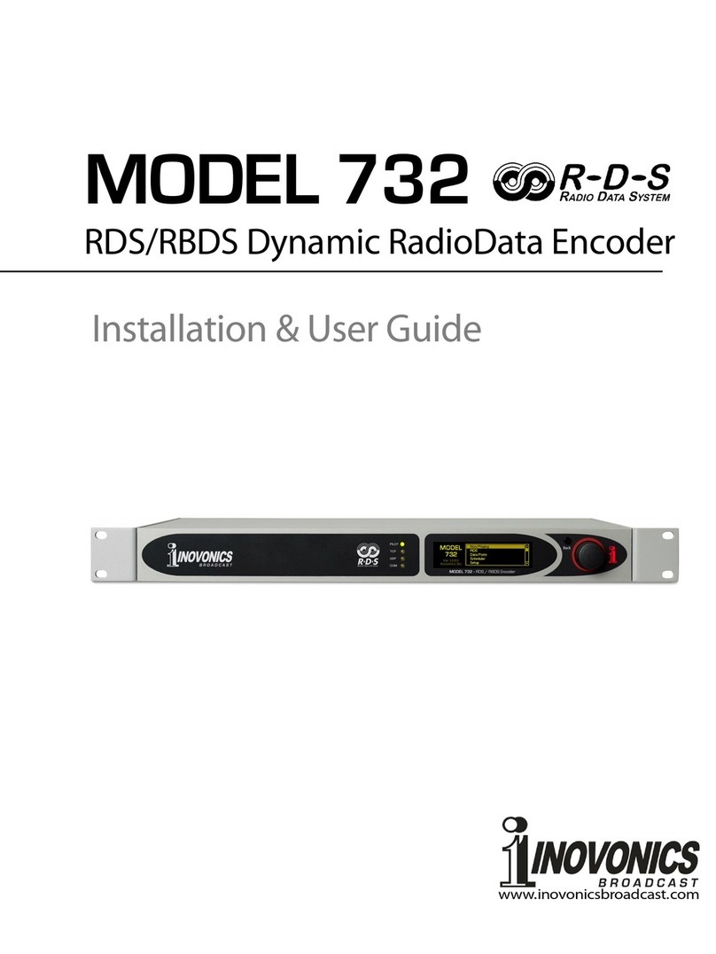
Inovonics 730 User manual

PROGRAMMING AND OPERATION
INSTRUCTION MANUAL
MODEL 730
R
RR
R
D
DD
D
S
SS
S
R
RR
R
ADIO
ADIO ADIO
ADIO
D
DD
D
ATA
ATA ATA
ATA
S
SS
S
YSTEM
YSTEMYSTEM
YSTEM
‘RADIODATA’ ENCODER
Rev. 3 – February, 2010
(Advanced Scheduler • Increased RT+ and ODA Support)


—— USER’S RECORD ——
Model 730 – Serial No. ____________
Date Purchased __________________
Warranty Registered? —
PROGRAMMING AND OPERATION
INSTRUCTION MANUAL
MODEL 730
R
RR
R
D
DD
D
S
SS
S
R
RR
R
ADIO
ADIO ADIO
ADIO
D
DD
D
ATA
ATA ATA
ATA
S
SS
S
YSTEM
YSTEMYSTEM
YSTEM
‘RADIODATA’ ENCODER
5805 Highway 9 •Felton, CA 95018
TEL: (831) 458-0552 • FAX: (831) 458-0554
Visit our Website: www.inovon.com


— 1 —
TABLE OF CONTENTS
Section I - INTRODUCTION
MODEL 730 ENCODER PRODUCT DESCRIPTION .............................................. 5
The “Radio Data System” • General • Features
730 ENCODER TECHNICAL SPECIFICATIONS ................................................... 6
BLOCK DIAGRAM .................................................................................................. 7
UNPACKING AND INSPECTION ............................................................................ 8
THE RADIO DATA SYSTEM DEFINED .................................................................. 8
RDS: EUROPE vs. AMERICA ................................................................................. 8
RDS vs. RBDS or “What’s in a Name?”
RDS APPLICATIONS SUPPORTED BY THE 730 ENCODER................................ 9
AF • CT • DI • M/S • ODA • PI • PS • PTY • PTYN • RT • RT+ • TP • TA
Section II - INITIAL ENCODER SETUP
e
ee
eQ
QQ
QGETTING TO KNOW YOU eq
eqeq
eq ........................................................................... 13
SETTING THE REGIONAL MODE: RDS OR RBDS ............................................. 13
FRONT PANEL PROGRAMMING ........................................................................ 14
Navigating With the Jog Wheel • The ASCII Character Set
The Essential Enter Character ↵
↵↵
↵• Using Uppercase Letters
730 ENCODER MENU ITEMS DEFINED ............................................................. 16
HOOK IT UP OR KEEP PROGRAMMING? .......................................................... 24
Section III - SOFTWARE INSTALLATION AND INITIAL ENCODER SETUP
COMMUNICATING WITH THE 730 ENCODER ................................................... 25
ASCII Commands • UECP Operation
INSTALLING THE SOFTWARE ............................................................................ 26
Install Software First! • Microsoft .NET Framework
Installing the USB Driver
RUNNING THE SOFTWARE ................................................................................ 28
WRITING TO AND READING FROM THE ENCODEDR ...................................... 29
Reading From the 730 Encoder
FILE OPTIONS ...................................................................................................... 30
Reset to Factory Defaults
DEVICE SELECTION AND CONNECTION OPTIONS ......................................... 31

— 2 —
THE TERMINAL UTILITY ..................................................................................... 31
Using the Terminal Utility • Correcting Typing Errors
Updating the AF List • Saving to Non-Volatile Memory
Interrogating the 730 Encoder
ENCODER HOUSEKEEPING COMMANDS ........................................................ 34
Encoder Initialization • Encoder Reset • Firmware Version
THE SCHEDULER ................................................................................................ 34
Entering Schedules • Updating and Enabling Scheduled Events
Scheduler Files • Priority of Scheduled Events • ‘Open-Ended’ Events
DAYLIGHT SAVING TIME .................................................................................... 37
DYNAMIC DNS ..................................................................................................... 38
TCP MODE PASSWORD ..................................................................................... 38
UECP PORT SELECTION .................................................................................... 38
OTHER SETUP OPTIONS ................................................................................... 39
The M/S Switch • The DI Switch
Regional Mode • Header (for RS232) • Help
Section IV - SOFTWARE SETUP FOR ON-AIR OPERATION
PI AND PTY CODES ............................................................................................ 42
PI Code and the Built-In Calculator • PTY and PTYN Format Identifiers
THE PS FIELD - STATIC AND SCROLLING ........................................................ 44
Scrolling Speed • Parsing ‘Auto’ Modes
“Safe Scrolling” • ‘Block’ Message Transmission
THE DEFAULT SCROLLING MESSAGE ............................................................. 46
RADIO TEXT AND ‘RT+’ ...................................................................................... 47
DRTS Radio Text Speed
Radio Text Default Message and Tags
ALTERNATIVE FREQUENCIES ........................................................................... 49
TRAFFIC ALERTS ................................................................................................ 49
TA Timeout
CT - CLOCK TIME AND DATE ............................................................................. 50
SETTING THE RDS DATA DELAY ....................................................................... 51
Diversity and Profanity Delays
ENABLING/DISABLING THE RDS SUBCARRIER................................................ 51
Section V - ENCODER INSTALLATION
IMPORTANT INSTALLATION SEQUENCE NOTE .............................................. 52
MOUNTING .......................................................................................................... 52
Rack Requirement • Heat Dissipation

— 3 —
AC (MAINS) POWER ............................................................................................ 52
Fuseholder • Mains Voltage Selector • Power Cord
RADIO FREQUENCY INTERFERENCE (RFI) ...................................................... 53
Location • Ground Loops
SELECTION OF OPERATING MODES ................................................................ 53
“Regional Mode” Selection
Jumper Placement for Sidechain Connection
Jumper Placement for Loop-Through Operation
CONNECTING THE 730 ENCODER .................................................................... 55
Check That Jumper! • Sidechain Connection (Preferred)
Using a Dedicated 19kHz Sync Source
Loop-Through Connection • Composite STL
Manual Activation of the TA Flag
SETTING THE SUBCARRIER INJECTION LEVEL .............................................. 57
Setting Subcarrier Amplitude
The On-Screen RDS Level Display
Subcarrier Phase
Section VI - CONNECTING THE 730 ENCODER TO AUTOMATION
SERIAL CONNECTION ......................................................................................... 59
COM Port Auto-Detect • 1-Way Data Links
Disabling Responses • Changing Baud Rates
Multiple Addressability
AUTOMATION SYNTAX REQUIREMENTS ......................................................... 61
‘No Headers’ Operation
THE ODA ‘FREE FORMAT’ GROUPS .................................................................. 62
RAW= • RAW(n)= • ODA Auto-Repeat Feature
DATA INTERCONNECTION ................................................................................. 64
Computer or Terminal Requirements
Interconnect Cables • Modem Link • STL Receiver Cable
Section VII - NETWORKING THE 730 ENCODER
PORTS .................................................................................................................. 66
Port Assignments • IP Address Assignment
NETPASS Password Protection
Automation and Passwords
DYNAMIC DNS ..................................................................................................... 67
Dynamic DNS Defined • Dynamic DNS Providers
Dynamic DNS System Abuse • Status Messages

— 4 —
Section VIII - “RADIO TEXT PLUS”
RT+ TAGS ........................................................................................................... 70
An RT+ Tag Example • Using the RT+ Software Utility
COMMAND OPTIONS .......................................................................................... 73
RT+ Configuration • Toggle and Running Bits
THE DEFAULT RADIO TEXT MESSAGE ............................................................ 74
Section IX - APPENDIX
ENCODER COMMANDS AND PROMPTS ........................................................... 76
US AND EUROPEAN PTY LISTINGS .................................................................. 80
ALTERNATIVE FREQUENCY CHANNEL NUMBERS ......................................... 81
LIST OF RT+ CONTENT TYPES .......................................................................... 82
INOVONICS WARRANTY ......................................................(INSIDE BACK COVER)

— 5 —
Section I
INTRODUCTION
MODEL 730 ENCODER PRODUCT DESCRIPTION
The “Radio
Data System”
The Radio Data System allows the FM broadcaster to transmit
certain digital data along with his regu
lar audio programming.
Packets of data transmitted on a low-le el subcarrier identify
the station and its particular broadcasting ‘format,’ allow for
transmission of song information, date and time of day, ad er-
tising and other text messages, and perform additional ID, con-
trol and housekeeping functions.
General
The 730 Encoder is Ino onics’ top
-
of
-
the
-
line, full
-
function
d
y-
namic RadioData encoder capable of scrolling song titles and
other information on the RDS radio faceplate. All of the im-
portant static IDs, traffic and other ‘flags’ are supported, as
well as specialized ‘in-house’ applications.
The front-panel LCD screen, built-in diagnostics and safeguards
offered by the 730 Encoder allow for near-foolproof RDS im-
plementation at any FM radio station. E ery step has been tak-
en to guarantee simple, straightforward and safe operation.
Features
Leading features of the Ino onics 730 include:
•Conforms to European UECP standards and supports
“RT+” applications and song ‘tagging.’
•Works with irtually any broadcast playout (automation)
system. A unique “No Headers” mode supports unfor-
matted satellite-streamed text feeds.
•Offers USB, RS-232 Serial and TCP/IP-UDP/IP network
connecti ity.
•The front-panel LCD screen and jog wheel enable local,
menu-dri en data entry without need for a computer.
•Internal firmware and software diagnostics guarantee
fast network setup and foolproof encoder operation.
•Easily set up to transmit song titles, contests, billboard
updates, scrolling ad ertisements, etc. Operates with
third-party hardware and software for increased functio-
nality. Scrolling messages are automatically ‘parsed,’ or
broken into 8-character word groups for transmission, or
can be ‘safe-scrolled one character at a time.
•A built-in Scheduler can automatically transmit pre-
programmed scrolling messages or RDS commands based
on day, date and time.
•Con enient loop-through or failsafe ‘sidechain’ operation
with any exciter/stereo generator combination.

— 6 —
730 ENCODER TECHNICAL SPECIFICATIONS
Full specifications of the 730 Encoder are really too numerous
to list completely here in tabular form. Please use the Table of
Contents and refer to in-depth descriptions of arious features
where they are described in detail.
Standards Supported:
European CENELEC/UECP; United
States NRSC.
RDS Applications Supported:
PI, PS, PTY, TP, TA, RT, RT+, AF,
DI, M/S, ODA. (A detailed expla-
nation of these applications be-
gins on Page 10.)
Operating Modes:
Loop-Through:
In loop-through operation, the
RDS subcarrier is internally
mixed with the MPX input and
the combined signal is deli ered
to the RDS or MPX Output. The
encoder has unity gain in the
loop-through mode and accepts a
maximum le el of 5 olts peak-
to-peak corresponding to ±75kHz
carrier de iation.
Sidechain:
In sidechain operation, only the
RDS subcarrier appears at the
RDS or MPX Output. The moni-
tored MPX (or TTL sync) is used
solely to synchronize the 57kHz
RDS subcarrier with the 19kHz
stereo pilot.
Pilot or MPX Input:
An unbalanced, bridging (BNC)
input that accepts either the
composite/multiplex (MPX) signal
or 19kHz TTL-le el pilot sync
from the stereo generator. In the
absence of a 19kHz signal, the
730 re erts to an internal crystal
timebase.
RDS or MPX Output:
An unbalanced, 75-ohm (BNC)
output to feed a wideband input
of the FM exciter.
RDS Injection Level:
Subcarrier le el is adjustable
from the front panel or by soft-
ware command between zero and
3V p-p. The LCD screen gi es
both bargraph and p-p oltage
readouts.
RDS Data Dela :
Scrolling-PS, Radio Text and RT+
messaging may be delayed in
one-second increments, up to
120 seconds, to match profanity
and transmission di ersity de-
lays.
USB Port:
A front-panel USB port gi es
quick and easy access for encod-
er setup. All static messaging
may be quickly set with a laptop
PC.
Serial Data Port:
A rear-panel RS-232 port (DB9)
accepts static encoder program-
ming and dynamic messaging
from station automation. The
730 accommodates all common
data rates between 1200 and
115,200 baud. Supplied software
features an automatic port and
data rate ID utility to simplify ini-
tial connection and setup.
IP Network Port:
A rear-panel RJ-45 connector ac-
cepts multiple IP networking
connections using both TCP and
UDP protocols. Connected to a
router, the 730 may be accessed
o er a station’s Local Area Net-
work or the Internet.

— 7 —
TA Switching:
The temporary TA flag is set ei-
ther by a software command or
with a contact closure through a
rear-panel terminal strip. The
730 incorporates a programma-
ble TA-timeout utility to preclude
TA flag iolations.
Supplied Software:
730 Encoder software runs on
any PC using the Windows® XP or
later operating systems and sup-
ports USB, serial (COM) port or
network (IP) connecti ity. The
software is intuiti e, self-guiding
and contains numerous pop-up
and other Help files.
Power Requirements:
105–130VAC (0.250A Fuse) or
210–255VAC (0.125A Fuse),
50/60Hz; 10W.
Size and Shipping Weight:
1¾”H x 19”W x 8”D (1U); 8 lbs.
BLOCK DIAGRAM
Figure 1 is a simplified Block Diagram of the 730 Encoder. This
product pro ides most of its functionality through firmware
coding and utilizes a high degree of surface-mount de ice
(SMD) manufacturing technology. There are so few user-
ser iceable components in ol ed that schematic diagrams and
circuit descriptions are not included in this manual.
Figure 1 – Block Diagram, Model 730 RDS Encoder
DAC
CPU
MICROPROCESSORS,
TIMEKEEPING,
NON-VOLATILE
MEMORIES
19kHz
BPF
PLL
RDS/MPX
OUTPUT
TIMEBASE
(LOCK)
57kHz
BPF
BYPASS
RELAY
PILOT/MPX
INPUT
LCD DISPLAY
RECT.
SIDE LOOP
(INJ.
LEVEL)
RS-232
SERIAL PORT
USB
PORT
+5V
(
RDS
LEVEL)
NETWORK
PORT
JOG
WHEEL
TA
SWITCH
PROGRAMMABLE
DELAY

— 8 —
UNPACKING AND INSPECTION
As soon as the equipment is recei ed, inspect carefully for any
shipping damage. If damage is suspected, notify the carrier at
once, and then contact Ino onics.
We recommend retaining the original shipping carton and pack-
ing materials, just in case return or transshipment becomes ne-
cessary. If returned for Warranty repair, shipping damage sus-
tained as a result of improper packing for return may invali-
date the Warranty!
IT IS IMPORTANT to complete and return the Warranty Regis-
tration Card that accompanies this manual, or to register the
Warranty on the Company’s Website, www.ino on.com. This
assures co erage of the equipment under terms of the Warran-
ty, pro ides a means of tracing lost or stolen gear, and adds the
user to a database to recei e specific ser ice instructions or
software/firmware updates when issued.
THE RADIO DATA SYSTEM DEFINED
RDS is a digital data channel transmitted as a low-le el subcar-
rier abo e the range of the composite stereo program signal in
the FM broadcast baseband. The data transmission (baud) rate
is comparati ely low, yet it is quite robust because of redun-
dancy and error correction routines. The injection le el of the
57kHz RDS subcarrier is a relati ely low 3% to 5%, thus it does
not rob the broadcaster of significant program audio modula-
tion.
It is not within the scope of this Manual to co er the details of
RDS subcarrier coding and modulation. For this the reader is
directed to the Specification appropriate to his location, either
the CENELEC EN50067 Specification for Europe, or the United
States NRSC Specification. It is assumed that the user has some
familiarity with the concept of RDS as the balance of this Ma-
nual will deal exclusi ely with Ino onics 730 Encoder imple-
mentation.
In particular, the explanations of the arious messaging and
housekeeping functions afforded by RDS will help the reader
become more familiar with what the system has to offer and
how it can be used to the broadcaster’s greatest ad antage.
These explanations begin on Page 9.
RDS: EUROPE vs. AMERICA
The European Broadcasting Union (EBU) and its member coun-
tries originated the concept of “Radio Data” transmission. The
European RDS specification, CENELEC Standard EN50067, was
first published in 1984, and was subsequently re ised in 1986,
1990, 1991, 1992 and 1998.

— 9 —
European RDS rapidly grew in use following initial adoption of
the Standard. RDS is nearly uni ersal throughout Europe; it is
almost impossible to find a European FM broadcasting station
that does not carry a RadioData subcarrier.
The popularity of RDS in Europe is ery much in contrast with
initial reluctance on the part of US broadcasters to embrace this
technology. This can be ascribed to material differences in
broadcasting practices.
Almost without exception, FM broadcasting in the United States
is ‘detached’ and independent; that is, each station originates
its own programming. One exception might be America’s Na-
tional Public Radio, although for most of the broadcast day
e en NPR stations originate, or at least schedule, their own pro-
grams.
Much of European broadcasting is similar to the concept of
network radio that was common in the US prior to the 1950s.
In Europe, a central program originator may feed many trans-
mitting facilities of modest power situated throughout the
country. The European disposition toward lower-power trans-
mitters can be found on the ‘local radio’ le el as well, with relay
(re-broadcast) repeater transmitters at se eral different fre-
quencies to blanket a designated ser ice area.
The European concept of a service area equates to the US
broadcaster’s market. The subtle difference between these de-
signations further characterizes broadcasting practices and eth-
ics. RDS benefits the European broadcaster through almost an
altruistic endea or to be of service to his listeners. The US
broadcaster is marketing his programming, and is primarily in-
terested in how he can promote his station through RDS ‘brand-
ing,’ as well as creating additional re enue through song ‘tag-
ging,’ sending GPS-linked traffic updates and other interacti e
applications.
RDS vs. RBDS
or “What’s in
a Name?”
As the Radio Data System was de eloped in Europe, it i
s u
n-
derstandable that it is abbre iated RDS there. The first US im-
plementation of RDS differed sufficiently from the European
standard to warrant its being renamed the Radio Broadcast Da-
ta System, or RBDS to differentiate it from its European coun-
terpart. Differences between the two standards ha e been re-
conciled and minimized o er the years, yet RBDS pre ails as the
US designation. For the sake of clarity and simplicity, the more
generic and established term RDS will be used throughout this
Manual.
RDS APPLICATIONS SUPPORTED BY THE 730 ENCODER
The following is an alphabetical listing of RDS applications that
are fully supported by the 730 Encoder. The standardized RDS
application abbre iation is followed by an expansion of the ap-
plication name and a short explanation of the function.

— 10 —
AF List of Alternative Frequencies:
A broadcasting network, or
a pr
i-
ate broadcaster using low-power rebroadcast transmitters
(‘translators’) to fill holes in his co erage area, can include a list
of all frequencies where the identical program can be heard at
that ery time (synchronously). Upscale RDS recei ers con-
stantly search for the best signal that carries the ery same
program. When a stronger signal is found, the radio re-tunes
to it with no audible interruption. The principal utility of this
RDS function is with European radio networks and US stations
with translators. The 730 can hold as many as 25 Alternati e
Frequencies.
CT Clock Time and Date:
The Radio Data System is capable of se
t-
ting the date and time on RDS recei
ers equipped with a clock.
The 730 Encoder may be manually set to the current correct
time, or it will check the time and date automatically if con-
nected directly to the Internet. Pro ision is included for auto-
matic changeo er between Standard Time and Daylight Sa ing
Time (DST). This is detailed on Page 37.
DI Decoder Information:
This is one of se
eral ‘flags’ that con ey
yes/no or other ery basic data. This particular flag is meant
to tell the recei er whether the broadcast is monaural or is be-
ing transmitted in any of se eral methods of stereo or binaural
broadcasting. This is a rather esoteric and little-used function,
and only monaural and con entional stereo transmissions are
supported by the 730 Encoder.
M/S Music/Speech Switch:
This flag indicates whether music or
speech is the primary programming. The purpose of this func-
tion is not co ered well in the respecti e Standards, so it comes
as no surprise that it is not widely understood. In general, only
all-news or talk-radio stations would fly the Speech flag.
ODA Open Data Applications:
The 730 E
n
coder pro ides a method of
transmitting ‘raw,’ proprietary hidden data within legitimate
RDS groups, including ODA, FFG and TMC applications. This is
a special use of the encoder for non-
standard applications.
Additional notes can be found on Page 62.
PI Program Identification:
This block of data identifies the broa
d-
cast station with a hexadecimal numerical code representing
the ‘digital address’ of the station. The recei er processes the
PI code to assist automatic tuning features (station memories),
and to pre ent false switching to alternati e frequencies that
might be shared by broadcasters in nearby regions. The code
is assigned by the broadcasting authority in most countries,
but in the US and in Canada it can be calculated from a numer-
ical encoding of station call letters. Encoder software does this
automatically as described on Page 42.
PS Program Service Name:
This is the station’s
‘
street name
’
that
might typically appear on the recei er faceplate display. The
PS can be up to eight characters in length (including spaces)
and can be as simple as the station’s call letters (KWOW or
KWOW FM) or a slogan (NEWSTALK or LIVE 95). As the Program

— 11 —
Ser ice Name is displayed e e
n on aut
o
mobile recei ers, it was
really meant to remain ‘static.’
Because of dri ing safety considerations, broadcasters ha e,
from the beginning, been discouraged from making the PS ‘dy-
namic’; that is, to send long messages in a succession of 8-
character frames. As a matter of note, it remains a iolation of
both the CENELEC and the NRSC standards to flash or scroll the
PS display. Ne ertheless, this nefarious practice of ‘Scrolling-
PS’ has become ubiquitous, both in the US and abroad. The 730
Encoder has arious modes for message scrolling that offer a
safe alternati e to the static PS display. These are described
beginning on Page 44.
PTY Program Type:
The PTY data flag identifies the station format
from a list of pre-assigned categories. Many RDS recei ers are
able to seek the listener’s preferred listening preferences au-
tomatically. This helps a broadcaster catch a certain transient
audience share… long-distance truck dri ers for instance. Two
distinct lists, one for RDS and the other for RBDS, remain a ma-
jor disparity between the two systems. A listing of all PTY cat-
egories is gi en in the Appendix.
PTYN Program Type Name:
This is an 8
-
character ide
n
tifier that may
be used to further define the Program Type. It is not used by
the recei er to search for a specific format, but once the re-
cei er is tuned to the station the Program Type Name can fur-
ther detail the type of programming. Further notes are found
on Page 42.
Under some programming circumstances, the PTY identifier
may be made dynamic, changing between categories for a sta-
tion that ‘dayparts’ (changes its format for specific time pe-
riods). Howe er, the PTY code is not meant to change from
song to song or to accommodate a top-of-the-hour newscast.
RT Radio Text:
This is a 64
-
charac
ter block of plain text that the
listener is able to select for isual display, but on only those
radios that ha e an INFO or a TEXT button. Radio Text should
not be confused with scrolling-PS; they are two separate and
distinct messaging utilities that are a ailable simultaneously.
The Radio Text function is not typically a ailable on automobile
recei ers for legacy safety considerations. This has precipi-
tated the frowned-upon practice of instead scrolling the PS field
for song titles and other ‘dynamic’ messages. Radio Text has
become relegated to the display of static information, such as
the station’s call-in phone number or Web address, unless the
station runs RT+ applications.
RT+ Radio Text Plus:
RT+ allows newer
RDS radios
,
as well as
cell
phones and MP3 players (equipped with FM recei ers) to gi e
the listener interacti ity with specific elements within the Ra-
dio Text message. For example, RT+ enables song ‘tagging’ or
direct access to telephone numbers or Internet addresses that
appear in Radio Text. See Page 70 for further details.

— 12 —
TP Traffic Program Identification:
The TP flag identifies the station as
one that routinely broadcasts traffic bulletins for motorists as
part of its normal, e eryday programming. When the TP flag
logo is displayed on the recei er faceplate, the radio is search-
ing for traffic announcements. The radio keeps track of TP sta-
tions offering this ser ice to speed up the search-and-
switcho er process.
TA Traffic Announcement:
This is a
temporary
flag added to the RDS
data stream only as a traffic bulletin is being aired. Some RDS
car radios can be set to search for traffic bulletins among ari-
ous TP stations (see TP below) while tuned to a listener’s pre-
ferred program, or e en while playing a CD or MP3. As soon as
any TP station broadcasts a traffic bulletin, the recei er tempo-
rarily switches-o er to recei e it. When the bulletin is finished,
the recei er switches back to the listener’s original entertain-
ment choice.
The ‘takeo er’ nature of the TA function has spawned numer-
ous abuses, mostly in a misguided and e il attempt to ‘steal’
listeners. A naughty broadcaster might tease a listener he has
just ‘grabbed’ by mentioning some hot pop star inter iew that’s
up next on his station as he goes into his traffic update. Or he
might simply lea e the TA flag on inad ertently (or not!). The
730 Encoder incorporates a TA countdown timer that limits the
traffic announcement to a user-programmed maximum number
of seconds.

— 13 —
Section II
INITIAL ENCODER SETUP
e
ee
eQ
QQ
QGETTING TO KNOW YOU eq
eqeq
eq
This section of the manual will make you familiar with the 730
Encoder by taking you step-by-step through an initial pro-
gramming (setup) procedure. The encoder may then be con-
nected in the station’s airchain and placed in working ser ice.
This initial setup procedure is all done from the front panel us-
ing the LCD display and jog wheel. No computer or other tools
are required at this point, and setup may be done on an office
desktop or lunchroom table.
Later sections of the manual will gi e instructions for loading
and using the supplied Windows® software, which actually of-
fers a streamlined way to program the unit. But performing the
initial setup ‘by hand,’ as explained in the following steps, will
best familiarize the user with the equipment in a relaxed at-
mosphere and without fear of making embarrassing mistakes.
SETTING THE REGIONAL MODE: RDS OR RBDS
Despite the reconciliation of Standards between the historic Eu-
ropean Radio Data System (RDS) and the North American Radio
Broadcast Data System (RBDS), some differences do remain.
These must be factored into encoder setup before the 730 can
be programmed properly. This is easily done, and once the re-
gional mode is selected, this needs ne er to be addressed again.
Plug in and turn on
the 730 Encoder. A
“splash screen” will
first appear and, after
a short inter al, will
re ert to the sequence
of numbered menus.
“Splash Screen”
Menu Sequence
With any numbered menu showing, push and hold down the jog
wheel. After se eral seconds, the splash screen will again ap-
pear. While continuing to hold down the jog wheel, turn it until
the proper designation appears in the top-right corner of the
display; either RBDS Encoder for North America, or RDS En-
coder for the Rest of the World, as shown here:

— 14 —
FRONT-PANEL PROGRAMMING
The 730 Encoder may be programmed almost entirely from the
front panel, although this is more tedious than using a comput-
er and the supplied Windows® software or the built-in Terminal
utility. But because an understanding of the LCD display is es-
sential regardless of how the encoder is initially programmed,
this method explains the LCD screens and teaches how to pro-
gram the unit locally if a computer is not a ailable.
Navigating and
Editing With
the Jog Wheel
The jog wheel, marked
SELECT
, allows the u
s
er to scroll up
and down through the 81 menu items. Once landing on one of
the menus that can be edited, pushing the jog wheel will then
enter that menu, and a flashing cursor ‘block’ will mark either a
alue that can be changed or the first alphanumeric character
that may be entered or edited. (The jog wheel may be locked
against inad ertent ‘bumping’ in Menu 77.)
The ASCII
Character Set
Characters in the ASCII set are in an order esta
b
lished by some
arcane Standard. You will notice that the uppercase and lower-
case components of the alphabet are separated by blocks of
numerals and symbols, some of which may conjure up images
of satanic rituals.
For practice, turn the jog wheel to Menu 03, the Dynamic PS, or
DPS field. This field holds up to 128 characters, which can
show anything from a static 8-character PS ‘street name’ to
whate er scrolling-PS text is resident in the buffer. As recei ed,
the 730 Encoder should show this:
Now push the jog wheel to enter the menu. A blinking cursor
will co er the first character that can be edited:
At this point the jog wheel can be turned to bring any ASCII
character into iew. Put in your call letters, starting with a K, or
a W if you are on the east coast or a C if you are Canadian, and
then press the jog wheel again to go to the next character.
Change the text howe er you like, pushing the jog wheel to na-
igate to the remaining characters until you ha e completed
your entry in the DPS field.

— 15 —
To back up to a pre ious character, push and hold the jog
wheel down. The cursor will back up one character at a time at
a fixed rate. If the blinking cursor backs up all the way and
lea es the screen on the left-hand side of the data entry area,
any changes that ha e been made will be cancelled. (This is al-
so the way to exit the screen without making any changes if the
screen was entered inad ertently.)
The Essential
Enter Character
↵
↵↵
↵
Once the field is filled
-
in, you
must
insert an ‘E
n
ter’ character,
the little arrow pointing to the left in the illustrations. The En-
ter character ↵
↵↵
↵
is for internal housekeeping only and will not
show on the listener’s radio. You’ll find the Enter character
with the jog wheel as the fifth character following the lower-
case ‘z.’
Once ↵
↵↵
↵
has been dialed-in, the next push of the jog wheel will
erase any lefto er characters to the right of your entry and dis-
play the word Set! in the corner of the display as the encoder
accepts the entry into memory.
If you are simply changing letters in an entry, it is not neces-
sary to re-enter them all. Just press the jog wheel repeatedly
until the blinking cursor reaches the ↵
↵↵
↵ and exits the display on
the right-hand side.
At this point the jog wheel is once again free to na igate among
the menus.
This ↵
↵↵
↵ operation is essential in many of the menu data-entry
fields, as noted under the arious menu items described from
here on.
Here’s an example of an 8-character ‘static’ PS that simply iden-
tifies the station:
And a ‘Dynamic-PS’ scrolling message that will repeat o er and
o er:
This is the general procedure for jog wheel editing, but there
are some ariations and exceptions that will be discussed under
the appropriate headings in the menu list that follows.
Using Uppercase
Letters
We ad ise using all uppercase (capital) letters with any RDS
messaging application. Many radios cannot show the full ASCII
set because of their own display limitations. Lowercase letters
and special symbols may not show at all on these radios.

— 16 —
730 ENCODER MENU ITEMS DEFINED
The following tabulation defines and discusses the 81 separate
menus that may be called up for display on the front-panel LCD
screen. Many of these menus may be set or edited with the
front-panel jog wheel. This allows on-site programming with-
out the necessity of connecting a computer, although the sup-
plied Windows® software does much of this automatically and
far more easily.
The jog wheel is rotated to select the menu for editing, pushed
to enter the menu, and then rotated or pushed again to na i-
gate through the menu. Generally a final push accepts the en-
try and displays: Set! on the LCD screen. The jog-wheel edit-
ing procedure will be detailed for each of the menu listings that
follow.
Menu No
.
Menu Item Descri
p
tion
Jog Wheel Editing Pr
o
cedure
01
The STATUS menu screen is intended as the ‘d
e-
fault’ display of the 730 Encoder. This screen:
a …shows whether the encoder is locked to the
stereo pilot or is running off the encoder’s in-
ternal crystal timebase;
b …displays the static or dynamic PS messag-
ing that is being sent over the air at that pre-
cise instant;
c …gives a flashing alarm for the duration of a
TA flag;
d …shows when Scheduler events are being
transmitted;
e …shows when the RDS subcarrier has been
turned off.
No jog wheel action is associated with this menu
screen.
02
This screen displays the incoming pr
o
gramming
data from a controlling computer or the station’s
playout system. Programming data is shown in real
time as it is received through any of the encoder’s
data ports. What appears here is exactly what the
encoder is receiving; OK and NO responses are
displayed after each incoming command, showing
that commands are valid or not. The screen auto-
matically clears after two minutes of inactivity. A
complete encoder data refresh will generally scroll
rapidly across the LCD and spill out of the window.
When commands are sent one-at-a-time using the
software Terminal utility (Page 31 , the data and its
syntax can be read completely. This screen is use-
ful for troubleshooting the possible corruption of
data sent from the studio to the transmitter site via
an STL serial data link, local area network or Inter-
net, and to verify command syntax.
No jog wheel entry is associated with this menu
screen, but pushing the jog wheel will clear the
screen of data prior to the two-minute timeout.
Table of contents
Other Inovonics Media Converter manuals
Popular Media Converter manuals by other brands

Black Box
Black Box AC135A-R2 Specifications

Silvercrest
Silvercrest SVG 2.0 A2 User manual and service information

foc.us
foc.us Harmony 2ES user manual

3One data
3One data IPMC100 Series Quick installation manual

Multi-COM
Multi-COM MUL-HDENC-C-100-NA user manual

TV One
TV One Edge Blender C2-2450A user guide