— 11 —
Stereo Pilot Requirement
The 703 encoder does not have an interna c ock for free-
run operation. This means that it must samp e the compo-
site baseband signa and ock to the 19kHz stereo pi ot.
The encoder wi not generate the RDS subcarrier without a
stereo MPX samp e and thus is not suitab e for monaura
broadcasting. (See MPX Sample Input Specification on Page
3.)
Setting the RDS Injection Level
The optimum injection eve for the RDS subcarrier is typi-
ca y 3.5% of tota modu ation (carrier deviation). Determin-
ing a correct setting for the front-pane INJECTION LEVEL
contro is a necessary routine but not a ways easy. The
57kHz subcarrier is BPSK-modu ated, spreading the spec-
trum of the waveform and making a precise measurement
of frequency and amp itude a difficu t proposition. Injec-
tion of the RDS subcarrier is a ways referred to in terms of
its instantaneous peak eve .
Many FM modu ation monitors are not capab e of making an
independent measurement of RDS subcarrier injection eve .
In order to do this, the monitor requires a specia subcarrier
measurement fi ter centered at 57kHz. The Inovonics Mod-
e 531 is representative of top-qua ity mod-monitors that do
have this measurement capabi ity.
In addition to the Mode 531 mod-monitor, Inovonics a so
offers two other products that can prove he pfu in monitor-
ing RDS data and making injection measurements. These
are the Model 510 RDS Decoder/Reader and the Model 540
Subcarrier Monitor/Demod. Either product may be used in
conjunction with practica y any FM mod-monitor in com-
mon use. See particu ars at: www.inovon.com.
Neverthe ess, using care and taking certain imitations into
account, near y any conventiona mod-monitor may be used
to set RDS injection with reasonab e accuracy. This does
require a temporary interruption of the audio program,
however, which is probab y best done during a maintenance
period. Here is the procedure:
1. With the Mode 703 encoder disconnected from the exci-
ter, check that the mod-monitor shows tota carrier
— 12 —
modu ation at the accepted 100% figure for program
peaks.
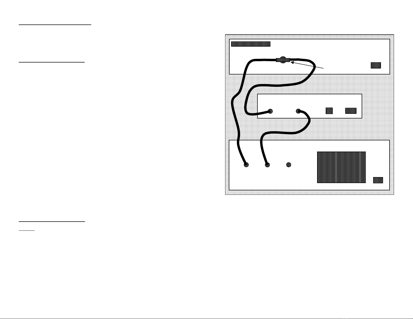
2. Disconnect the stereo generator (and any SCA generator)
from the exciter. Do make sure, however, that the ste-
reo-gen continues to feed a composite/MPX signa to the
703’s rear-pane 19kHz SYNC OR MPX SAMPLE connec-
tor.
3. With the front-pane INJECTION LEVEL contro turned
fu y counterc ockwise (this is a 15-turn contro ), connect
the RDS OUTPUT of the Mode 703 to a spare wideband
subcarrier input of the exciter. As the mod-monitor is
down-ranged to its most sensitive sca e, on y system
noise shou d be indicated, hopefu y at a neg igib e eve
if it is indeed readab e at a .
4. S ow y advance the INJECTION LEVEL contro c ockwise.
The mod-monitor wi begin to register the RDS subcar-
rier. Set this to the desired injection eve , typica y 3.5%
of tota peak modu ation.
NOTE: Many mod-monitors change from a peak re-
sponse to an a eraging response on the more sensitive
sca es. This presents a steadier and more meaningfu
measurement of system noise. Check the manufactur-
er’s documentation to verify the measurement response
of your mod-monitor on its ower ranges. If ow- eve
readings indeed prove to be average-responding indica-
tions, the monitor wi indicate an average RDS injection
eve that is about 4dB ower than the actua peak va ue.
Consequent y, set injection for an indicated 2.2% (with
a eraging response), which wi equate to the desired
peak deviation of 3.5%.
5. Reconnect the stereo-gen and any SCA or other subcar-
rier sources to the exciter. You may now see a very
s ight increase in tota modu ation on program peaks.
To maintain RDS and any other subcarriers at their
proper injection re ationship, the output of the stereo
generator (i.e.: the audio program eve ) may have to be
reduced by 0.5dB or ess to ensure that tota carrier
modu ation does not exceed the estab ished imit.