manuals.online logo
Brands
  1. Home
  2. •
  3. Brands
  4. •
  5. Inovonics
  6. •
  7. Receiver
  8. •
  9. Inovonics EchoStream EE4204 User manual

Inovonics EchoStream EE4204 User manual

© Inovonics, 2009 - www.inovonics.com
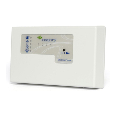
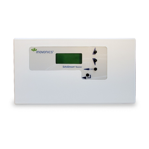
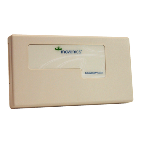
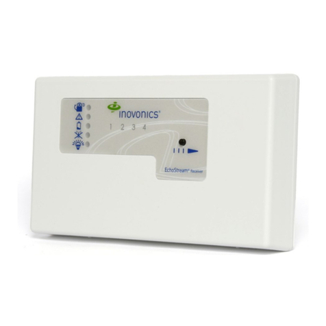
EE4204/R EchoStream®Receiver
Installation Instructions - 05426E
1 Overview
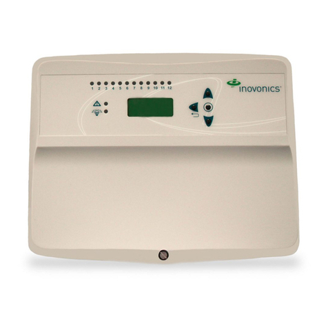
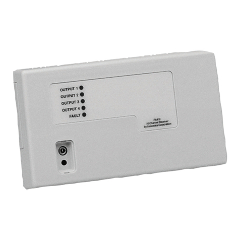
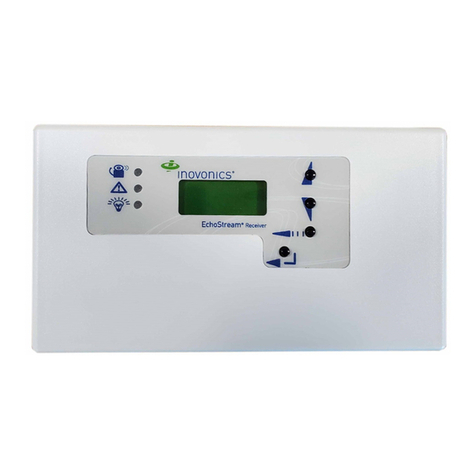
The EE4204/R receiver allows you to add up to four transmitters to any
application. With diversity reception and advanced signal processing,
Inovonics Wireless EchoStream technology is designed to minimize dead
spots in transmission areas.
1.1 Inovonics Wireless Contact Information
If you have any problems with this procedure, contact Inovonics Wireless
technical services:
• E-mail: [email protected]
• Phone: (800) 782-2709; (303) 939-9336
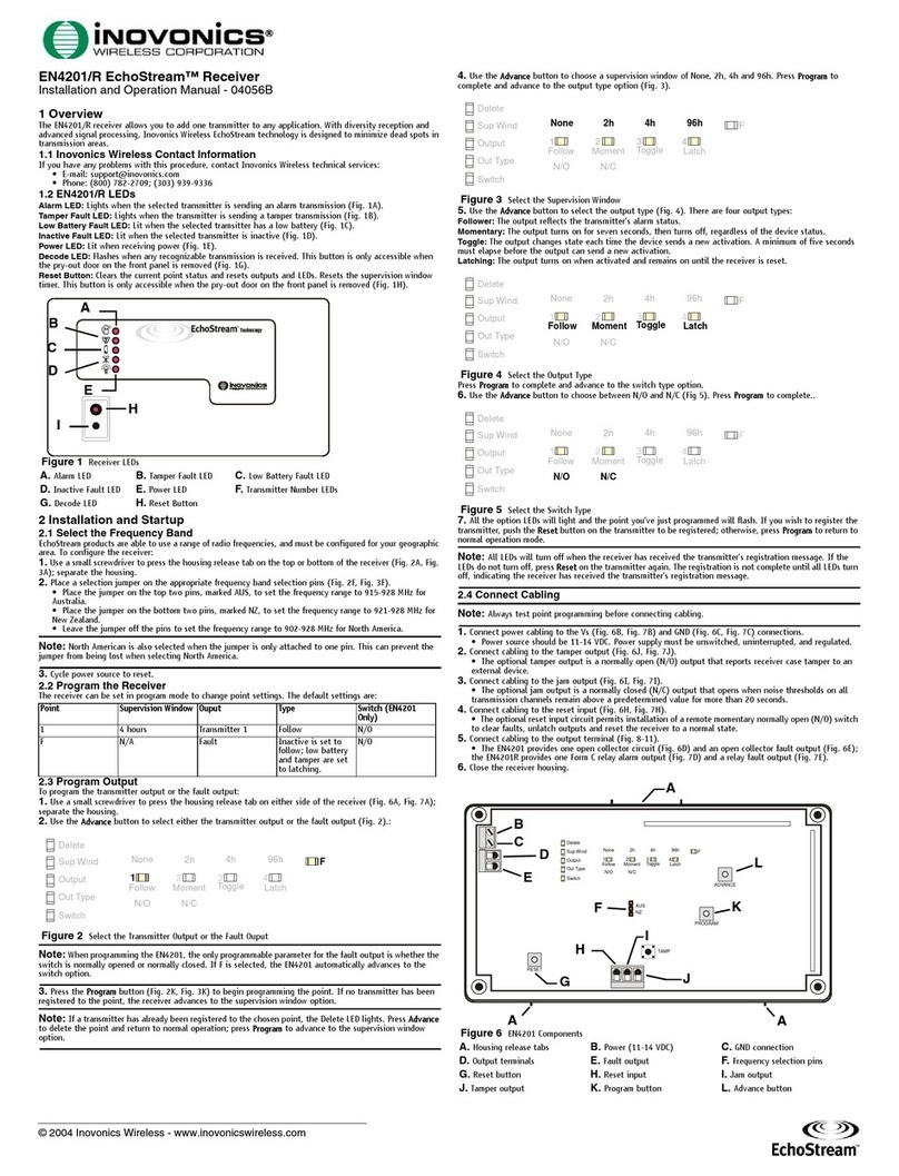
1.2 EE4204/R LEDs and Buttons
Figure 1 Receiver LEDs and Buttons
Most of the LEDs and buttons perform different function depending on
which mode the the EE4204/R is in.
Normal Operation Mode
Alarm LED: Lights when any transmitter is sending an alarm transmission.
Tamper Fault LED: Lights when any transmitter is sending a tamper
transmission.
Low Battery Fault LED: Lit when any transmitter has a low battery.
Inactive Fault LED: Lit when any transmitter is inactive.
Power LED: Lit when receiving power.
Transmitter Number LEDs: Lit when the transmitter is in alarm.
Advance Button: Press the Advance button to enter status review mode.
Decode LED: Flashes when any recognizable transmission is received.
This LED is only visible when the pry-out door or cover is removed.
Reset Button: Clears the current status for all points and resets all outputs
and LEDs. Resets the supervision window timers. This button is only
accessible when the pry-out door or cover is removed.
Status Review Mode
Alarm LED: Lights when the selected transmitter is sending an alarm
transmission.
Tamper Fault LED: Lights when the selected transmitter is sending a
tamper transmission.
Low Battery Fault LED: Lit when the selected transmitter has a low
battery.
Inactive Fault LED: Lit when the selected transmitter is inactive.
Power LED: Lit when receiving power.
Transmitter Number LEDs: Shows status of the transmitter assigned to
that number when lit. Use the advance button to scroll through transmitters.
Advance Button: Scrolls through transmitters to display status.
Decode LED: Flashes when any recognizable transmission is received.
This LED is only visible when the pry-out door or cover is removed.
Reset Button: Clears the current status for all points and resets all outputs
and LEDs. Resets the supervision window timers. This button is only
accessible when the pry-out door or cover is removed.
1.3 EE4204 Internal Components
Figure 2 EE4204 Components
1.4 EE4204R Internal Components
Figure 3 EE4204R Components
2 Installation and Startup
2.1 Connect Power Cabling
Before beginning startup, you will have to connect power to the receiver. To
connect power to the receiver:
1. Connect power cabling to the Power and GND connections.
• Power source should be 11-14 VDC. Power supply must be
unswitched, uninterrupted, and regulated.
AAlarm LED BTamper Fault LED CLow Battery Fault LED
DInactive Fault LED EPower LED FTransmitter Number LEDs
GAdvance Button HDecode LED IReset Button
A
B
D
E
F
G
C
H
I
AHousing release
tabs
BPower (11-14
VDC)
CGround connection
DOutput terminals EFault output FAdvance button
GReset button HReset input IJam output
JTamper output KProgram button LEchoStream Select
compatibility selection pins
MDecode LED
AHousing release
tabs
BPower (11-14
VDC)
CGND connection
DOutput terminals EFault output FAdvance button
GReset button HReset input IJam output
JTamper output KProgram button LEchoStream Select
compatibility selection pins
MDecode LED
A
B
C
D
I
J
H
L
E
AA
G
F
K
M
A
B
C
D
IJH
L
E
AA
M
F
K
G
© Inovonics, 2009 - www.inovonics.com 2
2.2 Enable EchoStream Select
To meet ETSI requirements, Inovonics has developed a new line of EE
868MHz-only products. These new 868MHz-only products are compatible
with older systems that include EchoStream Select (ES) products. If you
are using any ES products in your current system, you will need to enable
EchoStream Select compatibility on this new 868MHz-only product.
To enable/disable EchoStream Select compatibility:
1. To enable compatibility with ES products, place a selection jumper on
the ES selection pins.
Note: Selection jumpers are included in the EE4204/R hardware packet.
2. If no ES products are used in your system, remove the selection jumper
from the ES selection pins.
3. Cycle power.
2.3 Program the Receiver
Note: If changing programming for a point that already has a transmitter
registered to it, there is no need to re-register the transmitter. Changes to
point programming are automatically assigned to the transmitter registered
to that point.
The default settings are:
To program any of the four transmitter points or the fault output:
1. Use a small screwdriver to press the housing release tab on either side
of the receiver; separate the housing.
2. Use the Advance button to select any of the four transmitter points or
the fault output (Fig. 4).:
Figure 4 Select the Output to Program
Note: The only programmable parameter on the fault output is whether the
output is normally open or normally closed. If F is selected on an EE4204,
the EE4204 automatically advances to the switch option; an EE4204R will
not advance.
3. Press the Program button to begin programming the point. If no
transmitter has been registered to the chosen point, the receiver
advances to the supervision window option.
Note: If a transmitter has already been registered to the chosen point, the
Delete LED lights. Press Advance to delete the point and return to normal
operation; press Program to advance to the supervision window option.
4. Use the Advance button to choose a supervision window of None, 2h,
4h and 96h. Press Program to complete and advance to the output
option (Fig. 5).
Figure 5 Select the Supervision Window
5. Use the Advance button to select the output number (Fig. 6). Press
Program to complete and advance to output type option.
Figure 6 Select the Output Number
6. Use the Advance button to select the output type (Fig. 7). There are
four output types:
Follower: The output reflects the transmitter’s alarm status.
Momentary: The output turns on for seven seconds, then turns off,
regardless of the device status.
Toggle: The output changes state each time the device sends a new
activation. A minimum of four seconds must elapse before the output can
send a new activation.
Latching: The output turns on when activated and remains on until the
receiver is reset.
Figure 7 Select the Output Type
Press Program to complete and advance to the switch type option.
7. Use the Advance button to choose between N/O and N/C (Fig. 8).
Press Program to complete..
Figure 8 Select the Switch Type
8. All the option LEDs will light and the point you’ve just programmed will
flash. If you wish to register a transmitter to the point you’ve just
programmed, press the transmitter’s Reset button; otherwise, press
Program to save programming changes without registering a
transmitter.
Note: All of the alert LEDs will turn off when the receiver has received the
transmitter’s registration message, and the point number LED will light for
two seconds. The registration is not complete until all LEDs turn off and the
point number lights, indicating the receiver has received the transmitter’s
registration message. If this does not occur, press Reset on the transmitter
again.
2.4 Factory Config
The factory config option is used to restore the EE4204 to it factory
defaults.
Caution: The factory config will erase all programmed point, output, and
language information.
To restore the factory configuration defaults to the EE4204:
1. Hold down the Reset and Advance buttons.
2. With the buttons held down, cycle EE4204 power.
3 Connect Input/Output Cabling
1. Connect cabling to the tamper output.
• The optional tamper output is a normally open (N/O) output that
reports receiver case tamper to an external device.
2. Connect cabling to the jam output.
• The optional jam output is a normally closed (N/C) output that opens
when noise thresholds on all transmission channels remain above a
predetermined value for any 30 seconds in any 60 second window.
The jam output is is set to the follow output type.
3. Connect cabling to the reset input.
• The optional reset input circuit permits installation of a remote
momentary normally open (N/O) switch to clear faults, unlatch outputs
and reset the receiver to a normal state.
4. Connect cabling to the output terminals.
5. Close receiver housing.
Point Supervision
Window
Output Type Switch
(EE4204
Only)
1 4 hours 1 Follow N/O
2 4 hours 2 Follow N/O
3 4 hours 3 Follow N/O
4 4 hours 4 Follow N/O
F N/A Fault Inactive is set to follow; low
battery and tamper are set
to latching.
N/O
Delete
Out Type
Output
Sup Wind
Switch
F
Toggle
4h
Latch
96h
Follow
None
N/O
Moment
2h
N/C
1234
Delete
Out Type
Output
Sup Wind
Switch
F
Toggle
4h
Latch
96h
Follow
None
N/O
Moment
2h
N/C
1234
Delete
Out Type
Output
Sup Wind
Switch
F
Toggle
4h
Latch
96h
Follow
None
N/O
Moment
2h
N/C
1234
Delete
Out Type
Output
Sup Wind
Switch
F
Toggle
4h
Latch
96h
Follow
None
N/O
Moment
2h
N/C
1234
Delete
Out Type
Output
Sup Wind
Switch
F
Toggle
4h
Latch
96h
Follow
None
N/O
Moment
2h
N/C
1234
© Inovonics, 2009 - www.inovonics.com 3
Figure 9 EE4204 Terminals
Figure 10 EE4204R Terminals
3.1 Mount the Receiver
Caution: Mount the receiver in a location removed from metal. Metal
objects (duct work, wire mesh screens, boxes) will reduce RF range.
1. Use the provided anchors and screws to mount the receiver in a
location accessible for future maintenance.
2. Perform a walk test, activating each transmitter assigned to the receiver
and ensuring an appopriate response.
4 Specifications
Housing: 162 mm x 92 mm x 28 mm (6.38" x 3.60" x 1.10")
Operating environment: 0°- 60°C (32°- 140°F), 90% relative humidity,
non-condensing
Power requirement: 11 - 14 VDC; 150 mA (EE4204), ~400 mA max
(EE4204R with all five relays energized)
Current consumption: Approx. 135 mA; approx. ~400 mA max (EE4204R
with all five relays energized)
Output specifications: Open collector, drive down to .4V @ 100 mA
(EE4204); Form C relay 1A @ 28 VDC, 0.5A @ 30 VAC resistive load
(EE4204R); N/O receiver case tamper contact closure, N/C receiver jam
output indication.
Input specifications: A low is less than .5 V; a high is greater than 2.5 V.
Reset input: Contact closure, momentary low.
Receiver type: Frequency hopping spread spectrum
Number of points/transmitters: Four
Number of alarm outputs: EE4204: four open collector outputs;
EE4204R: four Form C relay outputs
Number of fault outputs: EE4204: one open collector output; EE4204R:
one Form C relay outputs
Figure 11 Tamper, Reset and Jam Circuits
4.1 Means of Conformity
Inovonics Wireless Corporation declares that the product listed above is in
conformity with the essential requirements and provisions of the following
Council Directives:
•R&TTEDirective
• Low Voltage Directive
•EMCDirective
and conforms to the following standards:
• EN 300 220 Receiver Class 1, Environmental Category 1
• EN 60950
• EN 301 489
5 Warranty/Disclaimer
Caution: Changes or modifications to this unit not expressly approved by
Inovonics Wireless Corporation may void the installer's authority to operate
the equipment as well as the product warranty.
Inovonics Wireless Corporation ("Inovonics") warrants its products
("Product" or "Products") to conform to its own specifications and to be free
of defects in materials and workmanship under normal use for a period of
thirty-six (36) months from the date of manufacture. Within the warranty
period, Inovonics will repair or replace, at its option, all or any part of the
warranted Product. Inovonics will not be responsible for dismantling and/or
reinstallation charges. To exercise the warranty, the User ("User", "Installer"
or "Consumer") must work directly through their authorized distributor who
will be given a Return Material Authorization ("RMA") number by Inovonics.
Details of shipment will be arranged directly through the authorized
distributor.
This warranty is void in cases of improper installation, misuse, failure to
follow installation and operating instructions, alteration, accident or
tampering, and repair by anyone other than Inovonics.
This warranty is exclusive and expressly in lieu of all other warranties,
obligations or liabilities, whether written, oral, express, or implied. There is
no warranty by Inovonics that Inovonics product will be merchantable or fit
for any particular purpose, nor is there any other warranty, expressed or
implied, except as such is expressly set forth herein. In no event shall
Inovonics be liable for an incidental, consequential, indirect, special, or
exemplary damages, including but not limited to loss of profit, revenue, or
contract, loss of use, cost of down time, or interruption of business, nor any
claim made by distributor's customers or any other person or entity.
This warranty will not be modified or extended. Inovonics does not
authorize any person to act on its behalf to modify or extend this warranty.
This warranty will apply only to Inovonics Products. Inovonics will not be
liable for any direct, incidental, or consequential damage or loss
whatsoever, caused by the malfunction of Product due to products,
accessories, or attachments of other manufacturers, including batteries,
used in conjunction with Inovonics Products.
Note: E-mail [email protected] for a copy of the CE Declaration of
Conformity.
Vs
Jam output
Ground
Tamper output
Reset input
Caution: Incorrect
connections may
cause damage to the
unit
Output 1
Output 2
Output 3
Output 4
Fault
Vs
Jam output
Ground
Tamper output
Reset input
Caution: Incorrect
connections may
cause damage to the
unit
NC
COM
NO
NC
COM
NO
NC
COM
NO
NC
COM
NO
NC
COM
NO
GND
GND
GND
Tamper
Reset
Jam

This manual suits for next models

1

Other Inovonics Receiver manuals

Inovonics EchoStream EN4204 User manual

Inovonics

Inovonics EchoStream EN4204 User manual

Inovonics EN4204/R User manual

Inovonics

Inovonics EN4204/R User manual

Inovonics EN4016SK User manual

Inovonics

Inovonics EN4016SK User manual

Inovonics INOmini 661 Operation manual

Inovonics

Inovonics INOmini 661 Operation manual

Inovonics EchoStream EN4201/R User manual

Inovonics

Inovonics EchoStream EN4201/R User manual

Inovonics EE4216M EchoStream User manual

Inovonics

Inovonics EE4216M EchoStream User manual

Inovonics AARON 650 Operation manual

Inovonics

Inovonics AARON 650 Operation manual

Inovonics EN4000 User manual

Inovonics

Inovonics EN4000 User manual

Inovonics INO mini 679 Operation manual

Inovonics

Inovonics INO mini 679 Operation manual

Inovonics 630 Manual

Inovonics

Inovonics 630 Manual

Inovonics EchoStream EE4232M User manual

Inovonics

Inovonics EchoStream EE4232M User manual

Inovonics EchoStream EE4216MR User manual

Inovonics

Inovonics EchoStream EE4216MR User manual

Inovonics INOmini 674 Operation manual

Inovonics

Inovonics INOmini 674 Operation manual

Inovonics EN4200 User manual

Inovonics

Inovonics EN4200 User manual

Inovonics EchoStream EE4216MR User manual

Inovonics

Inovonics EchoStream EE4216MR User manual

Inovonics FA400 User manual

Inovonics

Inovonics FA400 User manual

Inovonics EchoStream EE4232M User manual

Inovonics

Inovonics EchoStream EE4232M User manual

Inovonics 610 Operation manual

Inovonics

Inovonics 610 Operation manual

Inovonics Inomini 633 Operation manual

Inovonics

Inovonics Inomini 633 Operation manual

Inovonics INOmini 402 Operation manual

Inovonics

Inovonics INOmini 402 Operation manual

Inovonics INOmini 673 Operation manual

Inovonics

Inovonics INOmini 673 Operation manual

Inovonics FA416 User manual

Inovonics

Inovonics FA416 User manual

Inovonics AM SiteStreamer+ SOFIA 567 Operation manual

Inovonics

Inovonics AM SiteStreamer+ SOFIA 567 Operation manual

Inovonics Ino 634 mini Operation manual

Inovonics

Inovonics Ino 634 mini Operation manual

Popular Receiver manuals by other brands

Chamberlain TRICODE quick start guide

Chamberlain

Chamberlain TRICODE quick start guide

HumanTechnik PR22+ user manual

HumanTechnik

HumanTechnik PR22+ user manual

TC Communications TC8916 user manual

TC Communications

TC Communications TC8916 user manual

Retekess TD121 user manual

Retekess

Retekess TD121 user manual

SkyLink WIRELESS SWITCH SW-18 user manual

SkyLink

SkyLink WIRELESS SWITCH SW-18 user manual

ALDEN AE-1800 instruction manual

ALDEN

ALDEN AE-1800 instruction manual

AODELAN E2 user manual

AODELAN

AODELAN E2 user manual

Rockford Fosgate punchPMX-3 Installation & operation

Rockford Fosgate

Rockford Fosgate punchPMX-3 Installation & operation

Ten-Tec RX-321 manual

Ten-Tec

Ten-Tec RX-321 manual

LG LH-790HTS owner's manual

LG

LG LH-790HTS owner's manual

THORLABS PDF10 Series Operation manual

THORLABS

THORLABS PDF10 Series Operation manual

Sony STR-D2090 operating instructions

Sony

Sony STR-D2090 operating instructions

Eager LED LVP603S user manual

Eager LED

Eager LED LVP603S user manual

Sony DRN-XM01C2 operating instructions

Sony

Sony DRN-XM01C2 operating instructions

RCA DXD406RD user guide

RCA

RCA DXD406RD user guide

Harman Kardon AVR 225 reference guide

Harman Kardon

Harman Kardon AVR 225 reference guide

Panoramic Panadaptor PCA-2 Handbook

Panoramic

Panoramic Panadaptor PCA-2 Handbook

Yamaha RX-V595 Service manual

Yamaha

Yamaha RX-V595 Service manual

manuals.online logo
manuals.online logoBrands
  • About & Mission
  • Contact us
  • Privacy Policy
  • Terms and Conditions

Copyright 2025 Manuals.Online. All Rights Reserved.