manuals.online logo
Brands
  1. Home
  2. •
  3. Brands
  4. •
  5. Inovonics
  6. •
  7. Receiver
  8. •
  9. Inovonics EN4200 User manual

Inovonics EN4200 User manual

2.5.20 357-05854-03 Rev A © Inovonics, 2020 - www.inovonics.com
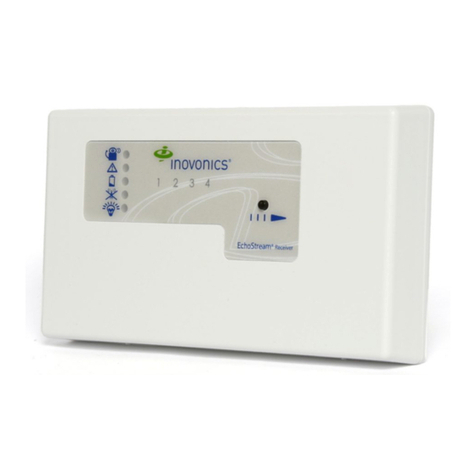
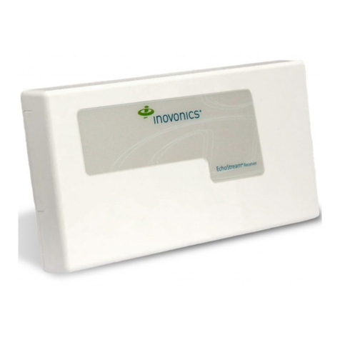
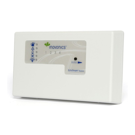
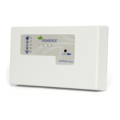
EN4200 Security Only Serial Receiver
Installation Instructions
1 Overview
The EN4200 security only serial receiver is a security only gateway that
uses reliable frequency-hopping, spread-spectrum technology to decode
radio frequency (RF) transmissions from security end devices and high-
power repeaters, and then outputs the decoded data to the application
controller in a common serial data format. The EN4200 is used for security
only applications.
1.1 Installing an Inovonics Security System
An EchoStream survey kit should be used to establish an EchoStream
system. The EchoStream survey kit measures the signal strength of high-
power repeater and sensor messages to help optimize your EchoStream
system.
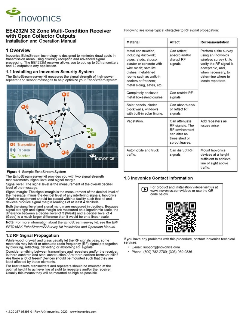
Figure 1 Sample EchoStream system
The EchoStream survey kit provides you with two signal strength
measurements: signal level and signal margin.
Signal level
The signal level is the measurement of the overall decibel level of the
message.
Signal margin
The signal margin is the measurement of the decibel level of the message,
minus the decibel level of any interfering signals. Inovonics equipment
should be placed within a facility such that all end-devices produce signal
margin readings of at least 4 decibels.
Both the signal level and signal margin are measured in decibels. Because
signal strength and signal margin are measured on a logarithmic scale, the
difference between a decibel level of 3 (Weak) and a decibel level of 4
(Good) is a much larger difference than it would be on a linear scale.
Note: For more information about the EchoStream survey kit, see the
EN7017 Survey Kit and App Installation and Site Survey Instructions.
Caution: The EchoStream system should be tested regularly to ensure
operation. To test: place the system in test mode, activate an end device,
and ensure an appropriate response.
1.2 RF Signal Propagation
While wood, drywall and glass usually let the RF signals pass, some
materials may inhibit or attenuate radio frequency (RF) signal propagation
by blocking, reflecting, deflecting or absorbing RF signals.
Consider anything between transmitters and repeaters and/or the receiver.
Is there concrete and steel construction? Are there earthen berms or hills?
Are there a lot of trees? Devices should be mounted such that they are
least affected by these elements.
For best results, transmitters and repeaters should be mounted at the
optimal height to achieve line of sight to repeaters and/or the receiver.
Usually this means they will be mounted as high as possible.
Following are some typical obstacles to RF signal propagation:
1.3 Inovonics Contact Information
If you have any problems with this procedure, contact Inovonics technical
services:
• E-mail: [email protected].
• Phone: (800) 782-2709.
1.4 What’s In The Carton
• Two drywall anchors.
• Two mounting screws.
• Two pieces of mounting tape.
• One frequency band selection shunt.
Material Affect Recommendation
Metal construction, including
ductwork; pipes; studs;
stucco, plaster or concrete
with wire mesh; satellite
dishes, metal-lined rooms
such as walk-in coolers or
freezers; metal siding, safes,
etc.
Can reflect, absorb
and/or disrupt RF
signals.
Perform a site survey
using an Inovonics
wireless survey kit to
verify the RF signal is
acceptable, and, when
necessary, to determine
where to locate
repeaters.
Completely enclosed metal
boxes/enclosures.
Can restrict RF
signals.
Solar panels, cinder block
walls, windows with built-in
solar tinting.
Can absorb and/or
reflect RF signals.
Vegetation. Can attenuate RF
signals. The RF
environment can
alter as trees shed
or sprout leaves.
Add repeaters as issues
arise.
Automobile and truck traffic. Can disrupt RF
signals.
Mount Inovonics devices
at a height sufficient to
achieve line of sight
above traffic.
For product and installation videos visit us at
www.inovonics.com/videos or use the QR
code below.
2.5.20 357-05854-03 Rev A © Inovonics, 2020 - www.inovonics.com 2
1.5 EN4200 Security Only Serial Receiver Internal
Components
Figure 2 EN4200 serial receiver components
1.6 EN4200 Security Only Serial Receiver Operation
LEDs
The following LEDs are used to monitor serial receiver operation:
Transmit LED: Lit when the serial receiver is transmitting data to the
application controller.
Receive LED: Lit when the serial receiver is receiving data from the
application controller.
Decode LED: Lit when the serial receiver is decoding an RF transmission
from another Inovonics device.
2 Installation and Startup
2.1 Installation Notes
• These products are designed to be maintained by professional
security technicians.
• Products are tested for indoor use.
• Do not mount wireless smoke detectors, co detectors, initiating device
transmitters or repeaters to removable surfaces, such as ceiling tiles.
• All products should be manually tested weekly.
• The EN4200 must be installed within 30 m (98.5 ft) of control unit.
• Low power transmitters shall be limited to a single initiating device.
2.2 Connect the Serial Cable
Caution: Long cable runs should not be adjacent to high current power
feeds. Keep cable lengths as short as possible to minimize cable
capacitance. Measure voltage supply at the serial receiver to ensure power
requirement is met for long cable runs.
1. Connect a serial cable to either the serial data port or the serial data
terminal. Cabling should meet the following specifications:
• Four-conductor 20AWG (or larger) stranded-tinned copper with PVC
insulation rated to 300 volts at 60°C (140°F). (Belden #8205, for
example.)
2. Route the cabling through either the bottom cabling knockout or the
side cabling knockout.
2.3 Select the Frequency Band
EchoStream products are able to use a range of radio frequencies, and are
shipped from Inovonics set for your geographic area.
• The jumper will be set on the two pins marked NZ to set the frequency
range to 921-928 MHz for New Zealand.
• The jumper will be set on the two pins marked AU to set the frequency
range to 915-928 MHz for Australia.
• The jumper will be removed to set the frequency band to 902-928
MHz for North America.
1. Ensure the frequency band is set for your geographic are.
2. If the frequency band is not set for your geographic area, place a
selection jumper on the appropriate frequency band selection pins to
select Australia or New Zealand, or remove it for North America.
Note: Only devices set for use in North America are configured for UL
installations.
3. If you have changed the frequency band and the device is powered on,
press the reset button to complete configuration.
2.4 Mount the Serial Receiver
Caution: Mount the EN4200 EchoStream serial receiver in a location
removed from metal. Metal objects (duct work, wire mesh screens, boxes)
will reduce RF range.
Note: A best practice is to ensure the EN4200 EchoStream serial receiver
is mounted in an easily accessible location for future maintenance.
4. Use the provided anchors and screws to mount the serial receiver in a
location accessible for future maintenance.
5. Close the serial receiver housing.
3 Specifications
Housing dimensions: 6.38" x 3.60" x 1.10" (162.0 mm x 91.4 mm x 27.9
mm).
Weight: 133 g (4.7 oz).
Power requirement: 10-13.5 Vdc, 100 mA.
Radio: Inovonics EchoStream.
Operating frequency: 902-928 MHz (USA) 915-925 MHz (AUS) 921-928
MHz (NZ).
Operating environment: 0-60°C, (32-140°F) up to 90% relative humidity
(non-condensing).
UL listings: UL 365, UL 636, UL 985, UL 1023, ULC/ORD-C1023-74, UL
1610, UL 1076, cUL.
Note: Inovonics supports recycling and reuse whenever possible. Please
recycle these parts using a certified electronics recycler.
4 Television and Radio Interference
This equipment has been tested and found to comply with the limits for a
Class B digital device, pursuant to Part 15 of the FCC Rules. These limits
are designed to provide reasonable protection against harmful interference
in a residential installation. This equipment generates, uses and can
radiate radio frequency energy and, if not installed and used in accordance
with the instructions, may cause harmful interference to radio
communications. However, there is no guarantee that interference will not
occur in a particular installation. If this equipment does cause harmful
interference to radio or television reception, which can be determined by
turning the equipment off and on, the user is encouraged to try to correct
the interference by one or more of the following measures:
• Reorient or relocate the receiving antenna.
• Increase the separation between the equipment and receiver.
• Connect the equipment into an outlet on a circuit different from that to
which the receiver is connected.
• Consult the dealer or an experienced radio/TV technician for help.
5 FCC Part 15 and Innovation, Science and
Economic Development Canada (ISED)
Compliance
This device complies with part 15 of the FCC Rules, and ISED license-
exempt RSS standard(s). Operation is subject to the following two
conditions: (1) this device may not cause interference, and (2) this device
must accept any interference that may cause undesired operation of the
device.
Le présent appareil est conforme aux CNR Innovation, Sciences et
Développement économique Canada applicables aux appareils radio
exempts de licence. L'exploitation est autorisée aux deux conditions
suivantes: (1) l'appareil ne doit pas produire de brouillage, et (2) l'utilisateur
de l'appareil doit accepter tout brouillage radioélectrique subi, même si le
brouillage est susceptible d'en compromettre le fonctionnement.
AHousing release tab BFrequency band selection pins
CSerial data port DSerial data terminal
EBottom cabling knockout FSide cabling knockout
GTransmit LED HReceive LED
IDecode LED JReset button
KTamper button spring
F
E
C
D
B
GH
I
AJ
K
2.5.20 357-05854-03 Rev A © Inovonics, 2020 - www.inovonics.com 3
Caution: Changes or modifications not expressly approved by the party
responsible for compliance could void the user's authority to operate the
equipment.
6 Radiation Exposure Limits
6.1 FCC
This equipment complies with FCC radiation exposure limits set forth for an
uncontrolled environment. In order to avoid the possibility of exceeding the
FCC radio frequency exposure limits, human proximity to the antenna shall
not be less than 20 cm during normal operation and must not be co-located
or operating in conjunction with any other antenna or transmitter.
6.2 ISED
This equipment complies with ISED RSS-102 radiation exposure limits set
forth for an uncontrolled environment. This transmitter must be installed to
provide a separation distance of at least 20 cm from all persons and must
not be co-located or operating in conjunction with any other antenna or
transmitter.
Cet équipement est conforme avec ISED RSS-102 des limites d'exposition
aux rayonnements définies pour un environnement non contrôlé. Cet
émetteur doit être installé à au moins 20 cm de toute personne et ne doit
pas être colocalisé ou fonctionner en association avec une autre antenne
ou émetteur.

Other Inovonics Receiver manuals

Inovonics FA400 User manual

Inovonics

Inovonics FA400 User manual

Inovonics EchoStream EE4232M User manual

Inovonics

Inovonics EchoStream EE4232M User manual

Inovonics EN4000 User manual

Inovonics

Inovonics EN4000 User manual

Inovonics 630 Manual

Inovonics

Inovonics 630 Manual

Inovonics EN4216MR User manual

Inovonics

Inovonics EN4216MR User manual

Inovonics EchoStream EE4232M User manual

Inovonics

Inovonics EchoStream EE4232M User manual

Inovonics EchoStream EE4216MR User manual

Inovonics

Inovonics EchoStream EE4216MR User manual

Inovonics EN4204/R User manual

Inovonics

Inovonics EN4204/R User manual

Inovonics INOmini 674 Operation manual

Inovonics

Inovonics INOmini 674 Operation manual

Inovonics EN4016SK User manual

Inovonics

Inovonics EN4016SK User manual

Inovonics INOmini 661 Operation manual

Inovonics

Inovonics INOmini 661 Operation manual

Inovonics EchoStream EN4201/R User manual

Inovonics

Inovonics EchoStream EN4201/R User manual

Inovonics Ino 634 mini Operation manual

Inovonics

Inovonics Ino 634 mini Operation manual

Inovonics AARON 650 Operation manual

Inovonics

Inovonics AARON 650 Operation manual

Inovonics EE4216M EchoStream User manual

Inovonics

Inovonics EE4216M EchoStream User manual

Inovonics INO mini 679 Operation manual

Inovonics

Inovonics INO mini 679 Operation manual

Inovonics FA416 User manual

Inovonics

Inovonics FA416 User manual

Inovonics INOmini 673 Operation manual

Inovonics

Inovonics INOmini 673 Operation manual

Inovonics 610 Operation manual

Inovonics

Inovonics 610 Operation manual

Inovonics Inomini 633 Operation manual

Inovonics

Inovonics Inomini 633 Operation manual

Inovonics AM SiteStreamer+ SOFIA 567 Operation manual

Inovonics

Inovonics AM SiteStreamer+ SOFIA 567 Operation manual

Inovonics EchoStream EE4204 User manual

Inovonics

Inovonics EchoStream EE4204 User manual

Inovonics EchoStream EE4232MR User manual

Inovonics

Inovonics EchoStream EE4232MR User manual

Inovonics EchoStream EE4216MR User manual

Inovonics

Inovonics EchoStream EE4216MR User manual

Popular Receiver manuals by other brands

Extron electronics MTP 15HD A Series user manual

Extron electronics

Extron electronics MTP 15HD A Series user manual

APLIC 301784 user manual

APLIC

APLIC 301784 user manual

Erone SEL2641R433-S1 manual

Erone

Erone SEL2641R433-S1 manual

Sony ICF-SW35 operating instructions

Sony

Sony ICF-SW35 operating instructions

Duevi SINT-13 Installation and use manual

Duevi

Duevi SINT-13 Installation and use manual

cytiva A4/2 instructions

cytiva

cytiva A4/2 instructions

Marantz SR4300 user guide

Marantz

Marantz SR4300 user guide

Univers by FTE U4120 user manual

Univers by FTE

Univers by FTE U4120 user manual

Dimplex RF Installation and operating instructions

Dimplex

Dimplex RF Installation and operating instructions

Triax TR 305 user manual

Triax

Triax TR 305 user manual

Element ESTR 200 user guide

Element

Element ESTR 200 user guide

Sony CTE-A10 operating instructions

Sony

Sony CTE-A10 operating instructions

AEG MC 4457 instruction manual

AEG

AEG MC 4457 instruction manual

AMG AMG4784RN-CWDMn instruction manual

AMG

AMG AMG4784RN-CWDMn instruction manual

Yamaha RX-V2500 owner's manual

Yamaha

Yamaha RX-V2500 owner's manual

Sony STR-DE595 Dimensions

Sony

Sony STR-DE595 Dimensions

Vemco VR100 operating manual

Vemco

Vemco VR100 operating manual

Sherwood RD-5405 operating instructions

Sherwood

Sherwood RD-5405 operating instructions

manuals.online logo
manuals.online logoBrands
  • About & Mission
  • Contact us
  • Privacy Policy
  • Terms and Conditions

Copyright 2025 Manuals.Online. All Rights Reserved.