INOXPA SILPIG S0120 Manual

INSTALLATION, SERVICE AND
INSTRUCTIONS
SILPIG PRODUCT RECOVERY SYSTEM
INOXPA, S.A.
c/Telers, 54 Aptdo. 174
E-17820 Banyoles
Girona (Spain)
Tel. : (34) 972 - 57 52 00
Fax. : (34) 972 - 57 55 02
www.inoxpa.com
Original Manual
13.001.30.00EN_RevC
ED. 2010/11
www.sks-online.com
www.sks-webshop.com

EC DECLARATION OF CONFORMITY
(In accordance with Directive 2006/42/EC, annex II, part A)
We, the manufacturer: INOXPA, S.A.
c/ Telers, 54
17820 Banyoles (Girona) - Spain
Hereby declare that the products
FLUID RECOVERY SYSTEM SILPIG
Name Type
are in conformity with the provisions of the Council Directives:
Machine Directive 2006/42/EC. The products comply with the essential requirements of the
aforementioned directive and the following Harmonised Standards:
UNE-EN ISO 12100-1/2:2004
UNE-EN 953:1997
UNE-EN ISO 13732-1:2007
Pressure equipment directive 97/23/EC, the stated equipment has been designed and
manufactured in accordance with the requirements of this Directive.
Max working pressure: DN-40/1 ½” to DN-80/3” = 10 bar
Diameter: DN-25 < X< or = DN-100
Equipment category: Category I, determined according to Article 3, Section 1.3ª, first paragraph,
annex II, table 6
This material MUST have the CE marking.
Conformity Evaluation Module: A Module
In conformity with Regulation (CE) No. 1935/2004 on materials and objects intended to come into
contact with foodstuffs (repealing 89/109/EEC), in accordance with which the materials in contact with
the product do not transfer its constituents to the foodstuffs in quantities large enough to put human
health at risk.
Declaration of Incorporation (Directive 2006/42/EC, annex II, part B):
The aforementioned equipment shall not be commissioned until the machine in
which they will be incorporated has been declared as being in conformity with the
Machine Directive.
Banyoles, 2012
www.sks-online.com
www.sks-webshop.com
ED. 2010/11 1.Safety 3
1.Safety
1.1. INSTRUCTION MANUAL.
This instruction manual contains basic indications which should be fulfilled during the installation, starting and maintenance.
The information published in the instruction manual is based on updated information.
INOXPA reserves the right to modify this instruction manual without prior notice.
1.2. INSTRUCTIONS FOR START-UP.
This instruction manual contains vital and useful information to appropriately handle and maintain your equipment.
Not only should the safety instructions indicated in this chapter be observed and fulfilled, but so should the special measures
and recommendations included in the other chapters of this manual. These instructions should be kept in a safe location near
the installation.
1.3. SAFETY.
1.3.1. Warning symbols.
Danger for persons in general
Danger of injury caused by rotating
equipment parts.
Electrical danger
Danger! Caustic or corrosive agents.
Danger! Suspended loads
Danger to the correct operation of the
equipment.
Commitment to safety at the workplace.
Protective goggles requirement.
Strong magnetic field
1.4. GENERAL SAFETY INSTRUCTIONS.
Read the instruction manual carefully before installing and starting up the equipment. Contact
INOXPA in case of doubt.
This equipment is suitable for use in food-processing.
Do not use in processes with products and/or temperatures that are not compatible with the sealing
materials and/or the PIG. It is the responsibility of the system designer to determine this
compatibility.
The equipment must only be handled by qualified staff.
The compatibility of the electrical equipment is the responsibility of the designer of the system or
the person who determines its specifications.
1.4.1. During the installation.
The
Technical Specifications
of Chapter 8 should always be observed.
The installation and use of the valve/actuator should always be carried out in accordance with
applicable regulations regarding health and safety.
Do not use the equipment until you have checked that it is functioning properly. Once it has been
assembled, repaired, cleaned, or a change has been made, connect the air supply and the electrical
supply, and ensure that it has been assembled correctly with proper supervision of operation and
leaks.
www.sks-online.com
www.sks-webshop.com
4 1.Safety ED. 2010/11
Check that the shafts are perfectly aligned. If they are not properly aligned, the stem, the shaft due
to friction, bushing and seals may be damaged.
Firmly tighten all the static and connected parts to prevent them from coming loose. If the
equipment operates at high frequency or is installed where there is substantial vibration, ensure
that all the parts are firmly held in place.
Provide for possible pressure drops in the pneumatic circuit and/or faults in the electrical supply.
This may lead to safety problems in the installation.
Provide for emergency shutdowns.
Check the operation of the equipment when restarting after an emergency or unexpected shutdown.
The shaft and the PIG are magnetised, DO NOT approach magnetic metal elements as they have a
strong magnetic pull. Do not leave this item on metal tables or benches during handling. DO NOT
place close to metal tools and/or objects that can be attracted by the magnetic field.
The working lifetime of the PIG greatly depends on the quality of the installation: Interior finishing
of pipes, welds, cleanliness, and anything that may affect the smooth movement of the PIG.
The equipment must be installed and used in accordance with the good practices of the sector, and
only by qualified staff.
During the installation, all the electric work should be carried out by authorised personnel.
1.4.2. During operation.
The
Technical Specifications
of Chapter 8 should always be observed. Under no circumstances can the
limit values specified be exceeded.
Do not use in atmospheres where there are corrosive gases as this might damage the cylinder and
the seals.
Do not use in atmospheres with strong magnetic fields as this may adversely affect both the PIG
detectors and the piston.
The working lifetime of the PIG greatly depends on the quality of the installation: Interior finishing
of pipes, welds, cleanliness, and anything that may affect the smooth movement of the PIG.
The equipment must be used in accordance with the good practices of the sector and by qualified
staff.
NEVER touch the equipment and/or pipes that are in contact with the liquid during operation. If
working with hot products, there is a risk of burns.
The PIG circulates through the tubes at high speeds so the circuit must be designed to be safe, so
that it can NEVER get out during operation.
Do not handle the actuator when the installation is in operation and/or holds compressed-air
pressure.
The degree of water-protection of the ball detectors and the actuator detector is IP 67 (completely
protected from dust and immersion in water).
1.4.3. During maintenance
The
Technical Specifications
of Chapter 8 should always be observed.
NEVER disassemble the equipment until the pipes have been emptied. Bear in mind that the liquid in
the pipe may be dangerous or extremely hot. Consult the regulations in effect in each country for
these cases.
www.sks-online.com
www.sks-webshop.com

ED. 2010/11 1.Safety 5
The pipes must be depressurised before opening any part of the circuit, as the PIG may escape at
high speed and cause serious personal injury.
Do not leave parts loose on the floor.
When inspecting the equipment, first check on the measures preventing falling of displaced objects
and loss of control of the equipment, etc. Then cut the supply pressure, electrical power, and release
all the air. When starting up the machinery, check that everything is normal and that the actuator is
in the correct position and the detectors are giving the correct signal.
The shaft and ball are magnetised, do not approach magnetic metal elements as they have a strong
magnetic pull. Do not leave this item on metal tables or benches during handling. DO NOT place
close to metal tools and/or objects that can be attracted by the magnetic field.
The working lifetime of the PIG greatly depends on the quality of the installation: Interior finishing
of pipes, welds, cleanliness, and anything that may affect the smooth movement of the PIG.
All electrical work should be carried out by authorised personnel.
1.4.4. In compliance with the instructions.
Any non-fulfilment of the instructions may result in a risk for the operators, the environment and the machine, and may result
in the loss of your right to claim damages.
This non-fulfilment may result in the following risks:
Failure of important functions of the machines/plant.
Failure of specific maintenance and repair procedures.
Possibility of electric, mechanical and chemical risks.
Will place the environment in danger due to the release of substances.
1.5. GUARANTEE.
Any guarantee will be cancelled immediately and as a matter of law and, in addition, we will require compensation for any
claims of civil liability presented by third parties, in case:
The installation and maintenance work has not been carried out according to the instructions of this manual.
The repairs are not carried out by our personnel or have been carried out without our written authorisation.
The parts used are not INOXPA original parts.
Modifications have been carried out on our materials without written authorisation.
The material has been badly used, incorrectly used, or used with negligence or has not been used according to the
indications and intended use specified in this manual.
The general conditions of delivery already in your possession are also applicable.
Please do not hesitate to contact us in case of doubts or more complete explanations are required on specific data
(adjustments, assembly, disassembly, etc.).
www.sks-online.com
www.sks-webshop.com

6 2.Contents ED. 2010/11
2.Contents
1. Safety
1.1. Instruction manual. ......................................................................................................... 3
1.2. InstrucTions FOR START-UP............................................................................................. 3
1.3. Safety............................................................................................................................. 3
1.4. GENeRAL SAFETY InstrucTions......................................................................................... 3
1.5. Guarantee....................................................................................................................... 5
2. Contents
3. Receiving and Installation
3.1. Check the shipment ......................................................................................................... 7
3.2. DELIVERY AND UNPACKING............................................................................................. 7
3.3. IdentificaTION................................................................................................................. 8
3.4. LOCATION. ..................................................................................................................... 8
3.5. Assembly. ....................................................................................................................... 8
3.6. INSPECTING AND CHECKING ........................................................................................... 8
3.7. AIR connectION TO actuaTor. .......................................................................................... 8
4. Start-up
4.1. sTART-UP. ...................................................................................................................... 9
4.2. OPERATION. ................................................................................................................... 9
5. Operating problems: Causes and solutions
6. Maintenance
6.1. General information ....................................................................................................... 11
6.2. Maintenance.................................................................................................................. 11
6.3. Cleaning........................................................................................................................ 12
7. Assembly and disassembly
7.1. DISASSEMBLY/ASSEMBLY OF THE EQUIPMENT............................................................... 14
7.2. pig position ................................................................................................................... 16
7.3. ORIENTATION OF THE EQUIPMENT ............................................................................... 16
7.4. FLUID CONNECTIONS.................................................................................................... 17
7.5. POSITIONING THE DETECTOR....................................................................................... 17
8. Technical Specifications
8.1. Technical Specifications ................................................................................................. 18
8.2. EQUIPMENT DIMENSIONS ............................................................................................. 19
8.3. SILPIG EXPLODED VIEW AND PARTS LIST...................................................................... 20
8.4. PIG DETECTOR EXPLODED VIEW AND PARTS LIST ......................................................... 21
www.sks-online.com
www.sks-webshop.com
ED. 2010/11 3.Receiving and Installation 7
3. Receiving and Installation
3.1. CHECK THE SHIPMENT
The first thing to do on receiving the equipment is to verify that it matches the delivery note.
INOXPA inspects all the equipment before packing, although it cannot guarantee that the merchandise will arrive intact to the
user. For this reason, the equipment received and any other article should be checked and, if it is found not to be in good
condition and/or not all parts are included, the carrier should submit a report as soon as possible.
Each equipment has a manufacturing number engraved. Indicate the manufacturing number in all documents and
correspondence.
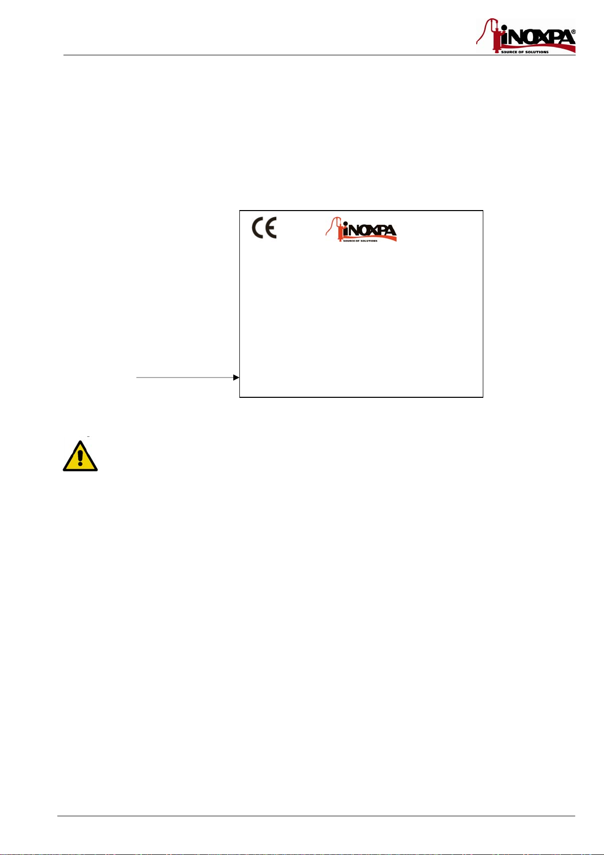
The equipment will have a sticker with the following information.
3.2. DELIVERY AND UNPACKING
INOXPA will not be responsible for the inappropriate unpacking of the valve and its components.
3.2.1. Delivery:
Check that all the parts indicated in the delivery slip:
Equipment
Its components (if supplied).
Delivery slip.
Instruction manual.
3.2.2. Unpacking:
Remove all traces of packing material from the equipment
or parts.
Inspect the valve or its constituent parts for possible damage caused during transport.
Avoid any possible damage to the valve and its components.
PIGGING SYSTEMS
MODELO: TAMAÑO:
MODEL: SIZE:
ACTUADOR/ACTUATOR
PRESION DE TRABAJO:min /máx
WORKING PRESSURE:min /max
Nº FABRICACION: AÑO
MANUFACTURING NR.: YEAR
Serial number
www.sks-online.com
www.sks-webshop.com

8 3.Receiving and Installation ED. 2010/11
3.3. IDENTIFICATION
S0120 11 06 52 040
HOUSING MATERIAL
06 – AISI 316L
NOMINAL DIAMETER
DIN
040
050
065 080
Inches
038
051
063
076
CONNECTION TYPE
CLAMP-77
WELD -00
DIN MALE -11
MODEL
SILPIG DIN – S0120
SILPIG O.D – S0121
SEALING MATERIAL
52 – EPDM
61 – Silicone
69 – Teflon
78 - Vitón
The buyer or user will be responsible for the assembly, installation, starting and operation of the
valve.
3.4. LOCATION.
Place the equipment in such a way as to facilitate inspections and checks. Leave room enough around the equipment for
service, disassembly and maintenance operations. It is very important to be able to access the air-connection device of the
actuator, even when in operation.
3.5. ASSEMBLY.
Once the location of the equipment has been established, it is possible to connect the piping using accessories (connectors).
Excessive stress should be avoided during the assembly of the equipment and special attention should be given to the
following:
Vibration that may be produced in the installation.
Expansion of the pipes during circulation of hot liquids.
The weight that the pipes can withstand.
Correct connection of the connectors and its seals.
3.6. INSPECTING AND CHECKING
Check the following before use:
Check that the PIG is magnetised in the shaft.
Apply compressed air three or four times, checking that the actuator completes the opening and closing operation
smoothly.
Check that the actuator pushes the PIG inside the piping and receives it with no problems.
Check that the PIG detectors provide the correct signal when passing the ball, and also when the actuator moves if there
are piston detectors.
3.7. AIR CONNECTION TO ACTUATOR.
Connect and check the air connections (1/8" Gas thread). Double acting actuator.
Check the air pressure and air characteristics (use clean air free of oils, chemical products, or any other product that
could damage the actuator).
The quality of the compressed air must conform to the specifications indicated in chapter 8 Technical Specifications.
www.sks-online.com
www.sks-webshop.com

ED. 2010/11 4.Start-up 9
4.Start-up
The start-up of the valve can be carried out provided the instructions indicated in Chapter 3 –
Receiving and Installation
are
followed.
4.1. START-UP.
Before start-up, the personnel in charge should be duly informed of the operation of the equipment
and the safety instructions to be followed. This instruction manual should be available to personnel
at all times.
The following should be taken into consideration before starting up the equipment:
Check that the pipe and valve are completely free from any traces of welding or other foreign matter. Carry out the
cleaning of the system if required.
Check that the alignment of the piston pushing the PIG with the actuator shaft enables smooth movement.
Check that the compressed air pressure at the intake to the actuator is that indicated in the Technical Specifications
(
Chapter 8
).
Bear in mind the quality of the compressed air in accordance with the specifications described in chapter 8 Technical
Specifications
Check that the equipment is moving smoothly. If necessary, lubricate with special grease or soapy water.
Check for possible leaks and check that all the pipes and connections are watertight and free from leaks.
Start up the equipment.
4.2. OPERATION.
Do not modify the operating parameters for which the equipment has been designed without written
prior authorisation from INOXPA.
Do not touch the moving parts of the coupling between the actuator and the body when the actuator
is connected to the compressed air.
Danger of burns! Do not touch the valve or pipes when hot liquids are circulating or when cleaning
and/or sterilisation is carried out.
www.sks-online.com
www.sks-webshop.com

10 5.Operating problems: Causes and solutions ED. 2010/11
5.Operating problems: Causes and
solutions
PROBLEM CAUSE/EFFECT SOLUTION
EXTERNAL LEAK.
THE PRODUCT LEAKS
THROUGH THE SHAFT The main seal is worn or deteriorated.
Replace the seals.
Replace the seals with others of
different material and more
appropriate for the product.
JERKING OF THE
SHAFT
Seals jamming.
The actuator does not operate effectively.
The bushing is worn or deformed
Check alignment of the shaft and
wear of the seals.
Check the compressed air supply
pressure.
Replace with another or repair
Replace with another
Check shaft alignment
THE SHAFT DOES NOT
PUSH OR COLLECT
THE PIG CORRECTLY
Deformation of gasket.
Incorrect operation of the actuator.
Worn actuator components.
Dirt in actuator.
Replace the seals with others of
different quality, if prematurely
deteriorated.
Check the actuator.
Check the compressed air
pressure.
THE PIG DETECTORS
DO NOT DETECT
The PIG is damaged or blocked up.
The detectors are not working correctly.
The PIG is driven by the compressed air at high speed and
does not give the sensor time to detect it as it passes.
Recover the PIG. Use a detection
pen to find the PIG in the
installation
Replace the PIG
Check the connection
Lower the air pressure
PREMATURE WEAR OF
THE BALL
The PIG is driven by compressed air at high speed,
creating considerable friction and hammering against the
PIG collector.
Installation in poor condition: poorly performed welds,
dirty pipes, inadequate internal finishing, etc.
Lower PIG recovery air pressure
Check installation
www.sks-online.com
www.sks-webshop.com
ED. 2010/11 6.Maintenance 11
6.Maintenance
6.1. GENERAL INFORMATION
This equipment, just like any other machine, requires maintenance. The instructions contained in this manual cover the
identification and replacement of spare parts. The instructions have been prepared for maintenance personnel and for those
responsible for the supply of spare parts.
Read thoroughly Chapter 8.
Technical Specifications
.
All replaced material should be duly eliminated/recycled according to the directives in effect in the
area.
Assembly and disassembly of the valves must only be carried out by qualified staff.
Before beginning the maintenance work, ensure that the compressed air is disconnected and the
pipes are not pressured.
6.2. MAINTENANCE.
The following is recommended for appropriate maintenance:
A regular inspection of the equipment, of the actuator and its components.
Keep a record of the operation of each equipment, noting any incidents.
Always have spare seals in stock.
During maintenance, pay particular attention to the danger indications indicated in this manual.
Do not touch moving parts when the actuator is connected to the compressed air.
The valve and pipes should not be pressurised during maintenance.
The valve should not be hot during maintenance. Danger of burns!
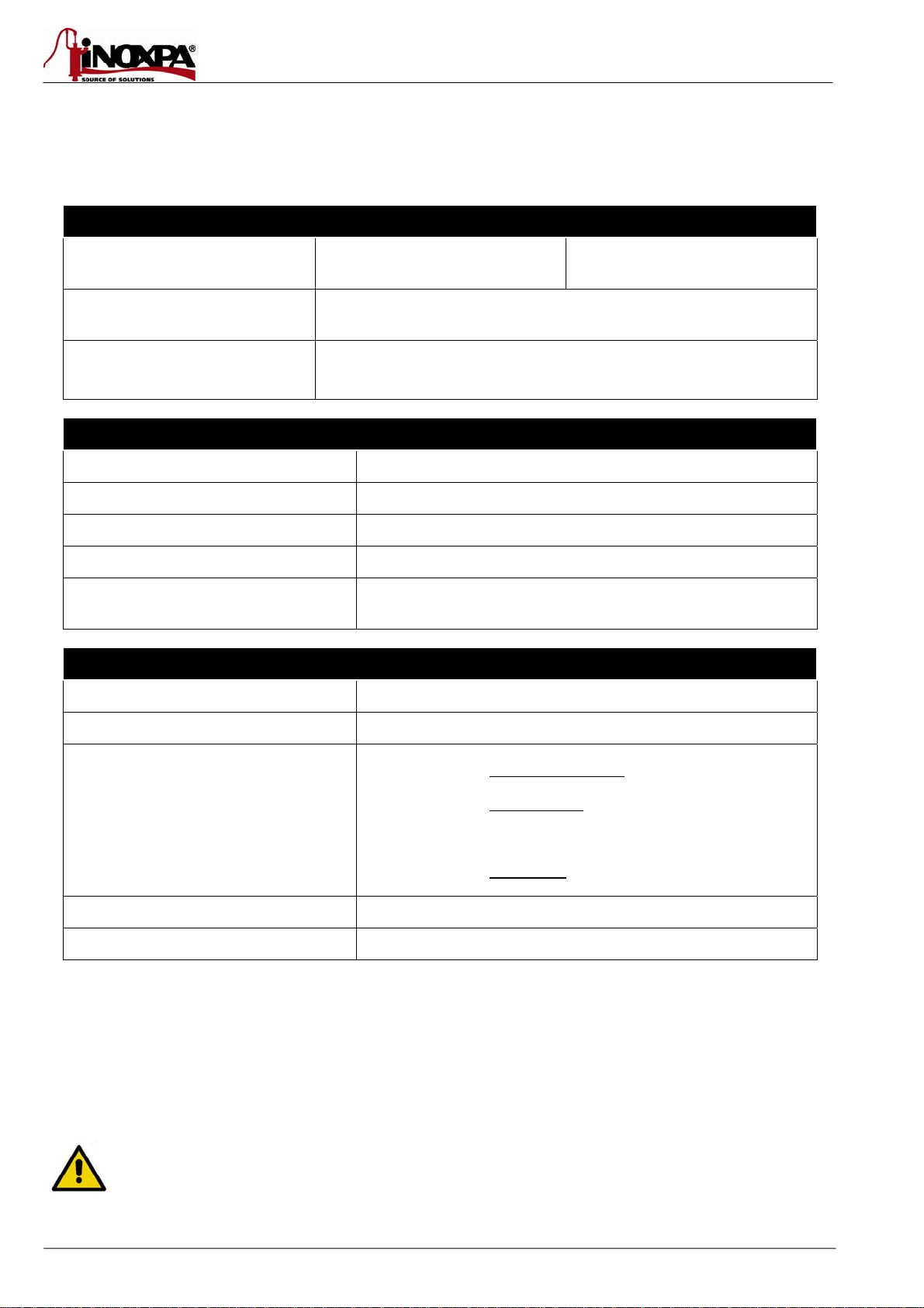
6.2.1. Maintenance of the seals.
REPLACEMENT OF SEALS
Preventive maintenance Replace after twelve (12) months.
Maintenance after a leak Replace at the end of the process.
Scheduled maintenance
Regularly check that there are no leaks and that the equipment operates
smoothly.
Keep a record for the equipment.
Use statistics to plan inspections.
Lubrication During assembly, apply lubricants compatible with the seal material. See the
following table.
SEAL COMPONENT LUBRICANT Class NLGI DIN
51818
NBR/ FPM/ VMQ Klübersynth UH 1 64-2403 3
EPDM/ NBR/ FPM PARALIQ GTE 703 3
The time interval between each preventive maintenance may vary according to the working conditions to which the valve is
submitted: Temperature, pressure, number of operations per day, type of cleaning solutions used, etc.
6.2.2. Storage
Storage of the valves should be carried out in an enclosed area, under the following conditions:
Temperature from 15ºC to 30ºC
Relative humidity <60%
Open-air storage of the equipment is NOT allowed.
www.sks-online.com
www.sks-webshop.com
12 6.Maintenance ED. 2010/11
6.2.3. PIG Maintenance
The wear of the PIG greatly depends on the quality of the installation: The surface finish of the piping, welds, cleanliness, and
anything that impedes the proper passage of the ball. It is also an influential factor whether or not it is driven by air, frequency
of use, etc. Regular inspection is therefore recommended according to the characteristics of the installation and its use.
Visually check that the PIG has not been deformed, worn, or cracked. The PIG must be replaced if any such defects are
detected.
6.2.4. Spare parts
To request spare parts, it is necessary to indicate the type of equipment, the code and the description of the part which can be
found in the Technical Specification chapter.
6.3. CLEANING
The use of aggressive cleaning products such as caustic soda and nitric acid may cause burns to the
skin.
Use rubber gloves during the cleaning process.
Always use protective goggles.
6.3.1. Automatic CIP (cleaning-in-place)
If the valve is installed in a system provided with the CIP process, its disassembly will not be required.
Cleaning solutions for CIP processes.
Only use clear water (chlorine-free) to mix with the cleaning agents:
a) Alkaline solution: 1% by weight of caustic soda (NaOH) at 70ºC (150ºF)
1 Kg NaOH + 100 l. of water = cleaning solution
or
2.2 l. NaOH at 33% + 100 l. of water = cleaning solution
b) Acid solution: 0.5% by weight of nitric acid (HNO3) at 70ºC (150ºF)
0.7 litres HNO3at 53% + 100 l. of water = cleaning solution
Check the concentration of cleaning solutions; it may cause the deterioration of the watertight seals
of the valve.
To remove any remains of cleaning products, ALWAYS perform a final rinse with clean water on completion of the cleaning
process.
Before beginning the disassembly and assembly work, clean the equipment inside as well as outside.
6.3.2. Automatic SIP (sterilization-in-place)
The process of sterilization with steam is applied to all the equipment including the pigging.
Do NOT start the equipment during the process of sterilization with steam.
The parts/materials suffer no damage if the indications specified in this manual are observed.
No cold liquid can enter the equipment till the temperature of the equipment is lower than 60°C
(140°F).
www.sks-online.com
www.sks-webshop.com

ED. 2010/11 6.Maintenance 13
Maximum conditions during the SIP process with steam or overheated water
a) Max. temperature: 140°C / 284°F
b) Max. time: 30 min
c) Cooling: Sterile air or inert gas
d) Materials: EPDM / PTFE (recommended)
FPM / NBR / VMQ (not recommended)
www.sks-online.com
www.sks-webshop.com

14 7.Assembly and disassembly ED. 2010/11
7.Assembly and disassembly
Proceed with caution. There is danger of personal injury.
Assembly and disassembly of the valves must only be carried out by qualified staff.
Always disconnect the compressed air before proceeding with any assembly or disassembly
operations. Do not touch moving parts when the actuator is connected to the compressed air.
The equipment and pipes should not be pressurised during assembly and disassembly.
The valve should not be hot during assembly and disassembly. Danger of burns!
The following tools are required to disassemble the valve:
4mm Allen key and 2 11m fixed wrenches (DN- 1.5", DN-2", DN-40, and DN-50)
6mm Allen key and 2 17mm fixed wrenches (DN-2.5", DN-3", DN-65, and DN-80)
7.1. DISASSEMBLY/ASSEMBLY OF THE EQUIPMENT
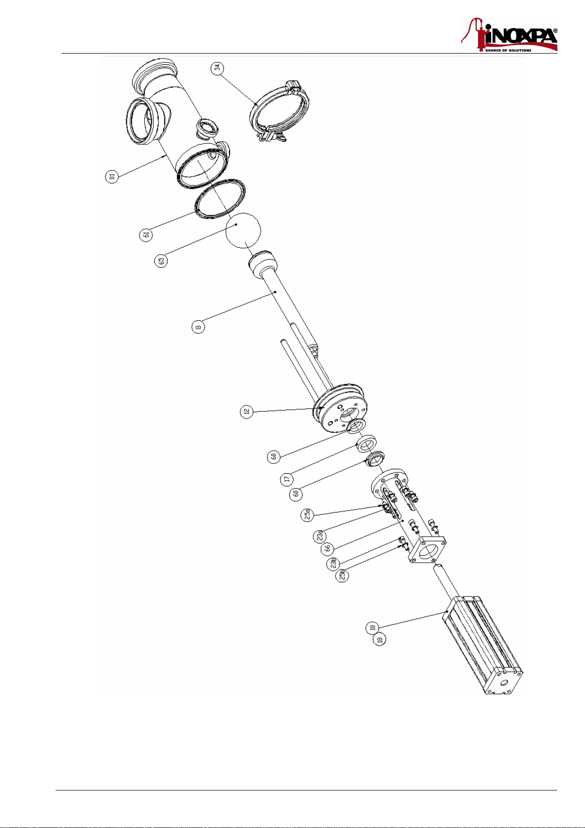
Disassembly
1. Disconnect the compressed air from the actuator (10).
2. Remove the clamp (34).
3. Remove the body assembly (01) from the rest and remove the gasket (61).
4. Handle the ball (65) carefully as it is magnetic (see
section -1.4.1
)
5. Remove the screws (23b) and their washers (25b) from the actuator (10).
6. Remove the shaft (08) from the actuator (10) (unthread shafts)
7. Remove screws (23a) and their washers (25a)
8. Remove lantern (66)
9. Remove seals (60) and bushing (17)
10. If necessary, disassemble the pipe detectors
Assembly
11. Place seals (60) and bushing (17) on the cover (12)
12. Mount the lantern (66) in the cover (12) with screws (23a) and washers (25b)
13. Pass the shaft (08) through the cover hole (12)
14. Connect the shaft (08) with the actuator (10), thread and ensure the thread is fixed with a Loctite 242 glue.
15. Connect the lantern (66) to the actuator (10) with screws (23b) and washers (25b)
16. Place the gasket (61) on the cap (12)
17. Place the body (01)
18. Connect the body (01) to the cap (12) using the clamp (34)
19. Place ball detectors. It must be placed at least 100 mm from the outlet hole so that it does not interfere with the ball's
magnetic field. (see section (7.5)
20. Connect the compressed air.
Before starting up the equipment, operate the actuator several times to ensure that it is moving
smoothly.
www.sks-online.com
www.sks-webshop.com
ED. 2010/11 7.Assembly and disassembly 15
www.sks-online.com
www.sks-webshop.com

16 7.Assembly and disassembly ED. 2010/11
7.2. PIG POSITION
The position of the PIG (65) must be checked during assembly/disassembly or replacement of the actuator.
POSITION 1: When the PIG is introduced into the pipe or is in a position awaiting the ball.
POSITION 2: when the PIG returns, it is in resting position.
POSICIÓN 1 (impulsión/recogida de PIG)
POSICIÓN 2
(
retorno
)
AIRE
AIRE
7.3. ORIENTATION OF THE EQUIPMENT
The guide rods of the PIG must remain on a perpendicular plane to the shaft of the outlet hole.
The equipment must be mounted horizontally, and the flow of the product must be in the direction indicated in section 7.4 Fluid
connections
AI
R
AIR
POSITION 1 (Propulsion / collection of PIG)
POSITION 2
(
return
)
www.sks-online.com
www.sks-webshop.com

ED. 2010/11 7.Assembly and disassembly 17
7.4. FLUID CONNECTIONS
The equipment has 4 holes, two of which are main ones: Product Inlet (1) and Outlet (2), which are connected to the main
piping of the installation, and two smaller secondary holes (3 and 4) for drainage and inflow of the ball-driving fluid and/or CIP.
Depending on the requirements, both secondary inlets or only one inlet (4) may be used while alternating between passage of
the drive fluid and drainage with a valve. Such design is up to the installation designer.
Drainage must necessarily have the port (4) as this is the one that is designed for drainage. If only (4) is used, (3) must be
capped with a blind bushing and standard INOXPA seal.
(1)
(2)
(3)
(4)
7.5. POSITIONING THE DETECTOR
The PIG detector must be placed at a certain distance from the outlet, as the shaft's magnetic field may interfere with the
detection, and the detector may give a signal even if the PIG has not passed. Place the detector at a distance of between 100
and 120 mm from the equipment outlet. Check that the detector is functioning correctly before starting up the equipment.
DO NOT connect the detector before carefully reading the manual and the technical document for the detector.
The connection must be made only be qualified staff.
PRODUCT INLET
SECONDARY
INLET
SECONDARY INLET
/ DRAINAGE
PRODUCT OUTFLOW
www.sks-online.com
www.sks-webshop.com
18 8.Technical Specifications ED. 2010/11
8. Technical Specifications
8.1. TECHNICAL SPECIFICATIONS
VALVE GENERAL DATA
Maximum working pressure
DN-40 / 80
DN-1.5"/3" 10 bar
Maximum working temperature
120ºC (250ºF) EPDM standard seals
(Other seals shall be adapted for higher temperatures)
Surface finish
In contact with the product: Ra 0.8 μm
External surfaces: satin-finished
EQUIPMENT MATERIALS
Parts in contact with the product
AISI 316L (1.4404)
Other steel parts
AISI 304 (1.4301)
Seals in contact with the product
EPDM (Standard) - NBR - VITON - SILICONE.
Surface finish
Parts in contact with the product.Ra. 0,8m
Type of connections
DIN 11851, BS-RJT, SMS, Clamp, Flanges, Macon.
PNEUMATIC ACTUATOR GENERAL DATA
Cycle
Double acting
Compressed air pressure (Actuator)
5-7 bar (72-101 PSI)
Compressed air quality
In accordance with DIN/ISO 8573.1
oSolid-particle content: Class-3 quality / Max. particle
size 5 microns / Max. particle density 5 mg/m3
oWater content: Class-4 quality / max. condensation
point +2 oC. If the equipment operates at high
altitude or low ambient temperature, the
condensation point must be adapted accordingly.
oOil content: Class-5 quality, preferably oil-free /
max. 25 mg oil per 1 m3air.
Continuous working temperature
-10ºC to +60ºC
Air connections
R1/8” (Gas)
RECOMMENDATIONS OF USE:
The maximum admissible output depends on the model and viscosity of the fluid driving the PIG. No greater than 1.5 m/s water
velocity is generally recommended. In the case of using compressed air as the PIG propellant, you should not drive the PIG with
dry pipes. The allowable air pressure depends on the model, conditions of use and the status of the installation.
Pressure is recommended to increase progressively until adequate pressure. Generally the recommended initial pressure
boosting product is between 1 to 2 bar, and may increase to a maximum of 4-5 bar, depending on the product and working
conditions.
When there is no product in the pipe, the return in the PIG should be done at low pressure. If the
impelling fluid is compressed air, a pressure of return between 0,5 – 1 bar is recommended,
depending on the installation, model and conditions of use. In case of doubt, please consult INOXPA
because a speed of return too high might seriously damage the PIG system.
www.sks-online.com
www.sks-webshop.com

ED. 2010/11 8.Technical Specifications 19
Tools/assembly tightening torque
Equipment size DN-40 / 50
DN-1.5” / 2” DN-65 / 80
DN-2.5” / 3”
Allen key 4 6
Tightening torque 7 Nm 10 Nm
8.2. EQUIPMENT DIMENSIONS
DN D1 D2 ABCDEL* DN D1 D2 ABCDEL*
40 38 26 116 91 173 52 74 588 1 ½” 34.8 22.1 115 88 169 50 74 586
50 50 26 104 87 168 58 74 589 2” 47.5 22.1 104 80 167 56 74 585
65 66 26 159 122 255 67 89 836 2 ½” 60.2 22.1 159 113 250 64 88 822
80 81 26 156 105 262 75 89 839 3” 72.9 22.1 141 107 245 70 88 824
* L may vary according to the actuator to be mounted. The length indicated is the length of the standard
INOXPA actuator.
www.sks-online.com
www.sks-webshop.com

20 8.Technical Specifications ED. 2010/11
8.3. SILPIG EXPLODED VIEW AND PARTS LIST
POS DN-40 DN-50 DN-65 DN-80
01 1S020-0110006040 1S020-0110006050 1S020-0110006065 1S020-0110006080
08 1S020-0800006040 1S020-0800006040 1S020-0800006065 1S020-0800006065
10 1S020-1000020040 1S020-1000020040 1S020-1000020065 1S020-1000020065
12 1S020-1200006040 1S020-1200006050 1S020-1200006065 1S020-1200006080
17 1S020-1700076040 1S020-1700076040 1S020-1700076065 1S020-1700076065
18 1P120-0030000623 1P120-0030000623 1P120-0030000623 1P120-0030000623
23a 1T112-0502004 1T112-0502004 1T112-0502004 1T112-0502004
23b 1T112-0803504 1T112-0803504 1T112-0803504 1T112-0803504
25b 1T427-0800004 1T427-0800004 1T427-0800004 1T427-0800004
25a 1T427-0500004 1T427-0500004 1T427-0500004 1T427-0500004
34 R0720-004065 R0720-004065 R0720-004114 R0720-004114
1S020-0500052040 1S020-0500052040 1W501-0540052040 1W501-0540052040
1S020-0500078040 1S020-0500078040 1W501-0500078040 1W501-0500078040
R1760-050076 R1760-050076 R1760-050104 R1760-050104
R1760-080076 R1760-080076 R1760-080114 R1760-080114
S8000-6100040 S8000-6100050 S8000-6100065 S8000-6100080
S8000-5200040 S8000-5200050 S8000-5200065 S8000-5200080
S8000-7800040 S8000-7800050 S8000-7800065 S8000-7800080
66 1S020-2100004040 1S020-2100004040 1S020-2100004065 1S020-2100004065
SHAFT SEAL (VITON)
CLAMP SEAL (VITON)
LANTERN
60
61
PIG (EPDM)
PIG (VITON)
65 PIG (SILICONE)
DIN 912 ALLEN SCREW
CLAMP SEAL (EPDM)
CASING COVER
GUIDE BUSHING
ELBOW 1/8" BSP
CODE
BODY
SHAFT
PNEUMATIC PISTON
DESCRIPTION
DIN 912 ALLEN SCREW
WASHER DIN 127 M8 (A2)
WASHER DIN 127 M5 (A2)
SHAFT SEAL (EPDM)
CLAMP
www.sks-online.com
www.sks-webshop.com
This manual suits for next models
1
Table of contents
Popular Commercial Food Equipment manuals by other brands


Diamond
Diamond AL1TB/H2-R2 Installation, Operating and Maintenance Instruction

Salva
Salva IVERPAN FC-18 User instructions

Allure
Allure Melanger JR6t Operator's manual

saro
saro FKT 935 operating instructions

Hussmann
Hussmann Rear Roll-in Dairy Installation & operation manual

Cornelius
Cornelius IDC PRO 255 Service manual

Moduline
Moduline HSH E Series Service manual

MINERVA OMEGA
MINERVA OMEGA DERBY 270 operating instructions

Diamond
Diamond OPTIMA 700 Installation, use and maintenance instructions

Diamond
Diamond G9/PLCA4 operating instructions

Cuppone
Cuppone BERNINI BRN 280 Installation

Arneg
Arneg Atlanta Direction for Installation and Use