Inscape Data AirGoogle NVC360 User manual

NVC 360 User’s Guide
Rev0.1(Dec. 2007)

NVC 360 User’s Guide
Rev.0.1 (Dec.2007) 2
Directions
NVC 360 series network cameras are designed for outdoor/indoor use. Don’t use NVC 360 in an environment
beyond the condition limit.
Be careful not to cause any physical damage by dropping or throwing the NVC 360 network camera.
Especially keep the network camera out of reach of children.
Do not disassemble NVC 360. Warrantee terms and conditions are not applied for the units that went through
disassembly process.
Use only the DC 12V power adapter which conforms to the specification in data sheet for NVC 360.
If you would like to use the NVC 360 for security, monitoring, please check the legal regulations within the
country.
Note
This equipment has been tested and found to comply with the limits for a Class A digital device, pursuant to
part 15 of the FCC Rules. These limits are designed to provide reasonable protection against harmful
interference in a residential installation. This equipment generate, use and can radiate radio frequency energy
and, if not installed and used in accordance with the instructions, may cause harmful interference to radio
communications. However, there is no guarantee that interference will not occur in a particular installation. If
this equipment does cause harmful interference to radio or television reception, which can be determined by
turning the equipment off and on, the user is encouraged to try to correct the interference by one or more of
the following measures
Reorient or relocate the receiving antenna.
Increase the separation between the equipment and receiver.
Connect the equipment into and outlet on a circuit different from that to which the receiver is
connected
Consult the dealer or an experienced radio/TV technician for help.

NVC 360 User’s Guide
Rev.0.1 (Dec.2007) 3
Warning & Caution
If you fail to read this information and
handle the product incorrectly, death or
serious injury may occur.
The unit should be installed by trained
personnel.
Always stop using when the product emits
smoke or abnormal heat.
Never install the product in area exposed to
oil or gas.
Never install the product on a ceiling that
cannot hold its weight.
Never touch the power cord with wet hands.
Clean only with dry cloth.
Never use the product in extremely high or
low temperature condition.
Never drop, hit strongly nor vibrate the
product.
Never expose the product to direct sunlight
or severe ray.
Never touch the front glass of the product.
This symbol is intended to alert the user to
the presence of un-
insulated “dangerous
voltage” within the product’s enclosure
that
can cause electric shock..
This symbol is intended to alert the user to
the presence of
important operating and
maintenance (servicing) instructions in the
literature accompanying the appliance.
Do not apply force to adjust Pan/Tilt
position. It may causes serious damage
Additional Warning & Caution
for NVC 360

NVC 360 User’s Guide
Rev.0.1 (Dec.2007) 4
Revision History
Date Rev. No Description
2007-12-19 0.1 Creation of the document

NVC 360 User’s Guide
Rev.0.1 (Dec.2007) 5
1. Introduction ......................................................................................................................................................... 6
1.1. Overview........................................................................................................................... 6
1.2. Features of NVC 360......................................................................................................... 6
1.3. Applications of NVC 360 .................................................................................................... 8
2. Product Description............................................................................................................................................. 9
2.1. Package Contents ............................................................................................................. 9
2.2. Preview............................................................................................................................. 9
2.3. PC Requirements ............................................................................................................ 10
2.4. Physical description......................................................................................................... 10
2.5. Specification of the analog camera module....................................................................... 13
2.6. Quick Installation Guide ................................................................................................... 15
3. Connecting NVC 360 to IP Network ................................................................................................................. 18
3.1. Connecting to LAN .......................................................................................................... 18
3.2. Connecting to xDSL/Cable Modem................................................................................... 19
4. IP-Installer ......................................................................................................................................................... 21
4.1. Main window of IP-Installer .............................................................................................. 21
5. Configuring NVC 360 in Administrative Mode .................................................................................................. 22
5.1. Log On............................................................................................................................ 22
5.2. Basic Setup..................................................................................................................... 24
5.3. Network Configuration ..................................................................................................... 26
5.4. User Admin & Time Setup ................................................................................................ 29
5.5. Sensor & Capture Setup .................................................................................................. 32
5.6. Alarm Device Setup ......................................................................................................... 34
5.7. Motion Region Setup ....................................................................................................... 36
5.8. PTZ Setup....................................................................................................................... 38
5.9. Encryption Set up ............................................................................................................ 40
5.10. Upgrade & Reset........................................................................................................... 42
5.11. Status Report................................................................................................................. 44
6. Tips for Using NVC 360 .................................................................................................................................... 45
6.1. Alarm (for Sensor input) and AUX(for Relay output) .......................................................... 45
6.2. Trouble Shooting ............................................................................................................. 47
6.3. Web Viewer..................................................................................................................... 49
6.4. How to upgrade NVC 360 firmware .................................................................................. 51
Appendix 1. On Site Installation of NVC 360 ........................................................................................................ 52
Table of Contents

NVC 360 User’s Guide
Rev.0.1 (Dec.2007) 6
1. Introduction
1.1. Overview
The NVC 360 is a state-of-the-art dual CCD vandal proof network camera which transmits synchronized video
and audio data in real time with D1 resolution at full frame rate. This is possible through MPEG4 CODEC
technology, which provides high quality video with highly compressed data streams. The NVC 360 can be
connected, controlled and monitored from a remote location through an IP connection over internet or intranet.
Unlike CCTV or DVR, the NVC 360 is easy to install and owner will experience cost and space savings in the
installation owing to the state of the art technologies embedded in the system. Based on Embedded Software
Solution (Embedded Web Server, Embedded Streaming Server, Network Protocol), the NVC 360 ensures
unprecedented performance and stability to be an ideal network camera solution for system integration solutions.
NVC 360 is offered with standard Ethernet interface.
1.2. Features of NVC 360
•
••
•State-of-the-art CPU, Codec & Embedded S/W
•
••
•Superior video compression – MPEG-4
•
••
•Max 30 frames/sec @ D1 resolution
•
••
•Full D1 Resolution with De-interlaced filter
•
••
•Http streaming based on CGI
•
••
•Full duplex audio communication (internal MIC & Speaker(1W))
•
••
•Synchronized 1CH audio & video data transmission
•
••
•Intelligent Bit Rate Control for flexible network deployment
•
••
•Enhanced Image Quality
•
••
•MPEG4+JPEG Dual Stream
•
••
•Embedded Streaming Server and Embedded Web Server
•
••
•Motion detected and event triggered alarm processing
•
••
•Easy recording and playback on client PC
•(1) alarm input & (1) relay output
•Wide range of network protocols supported
•Dual CCD (Color CCD for day and B/W CCD for night)
- CCD is exchanged according to the light condition
•
••
•Vandal Proof

NVC 360 User’s Guide
Rev.0.1 (Dec.2007) 7
•
••
•The same sensitivity with B/W Ex-view CCD. 0.003 lux.
•
••
•Integrated Heater
•
••
•System time management
RTC and with Time Server synchronization
1 Alarm sensor inputs / 1 relay outputs
Resolution
- NTSC : 720x480, 352x240, 176x144. - PAL/SECAM : 720x576, 352x288, 176x144
Remote administration control
Entire operational parameter set up, Software upgrade

NVC 360 User’s Guide
Rev.0.1 (Dec.2007) 8
Detailed Features for camera parts
1.3. Applications of NVC 360
IP surveillance (buildings, stores, manufacturing facilities, parking lots, banks, government facilities, military, etc.,
Real time Internet broadcasting
Remote monitoring (hospitals, kindergartens, traffic, public areas, etc.,)
Teleconference (Bi-directional audio conference)
Remote Learning
Weather and environmental observation
Polarity Protection of Power (DC12V)
This protection function prevents damage to
the domes power board if the dc supply is
connected with incorrect polarity.
DUAL CCD For extreme 0 Lux Surveillance
The power of LEDs is selectable, low or
high. (High is recommended for over 30m
surveillance )
The exchanging time of CCD or filter is
selectable.
Only DC 12V is available.
Operating Temperature down to – 40
degree Celcius with built in heater.
Various Surveillance Functions
Dome Housing
The elegantly designed aluminum body and Poly
Carbonate dome cover provide a very solid product for a
wide range of applications.
X-Y-Z Axis available.
It has ball-shaped bracket inside, so
you can install it any place you want.
Indoor / Outdoor applications
The domes small size and construction to IP
66 ingress protection rating make it ideal for
internal or external applications

NVC 360 User’s Guide
Rev.0.1 (Dec.2007) 9
2. Product Description
2.1. Package Contents
Open the package and check if you have the followings:
2.2. Preview
NVC 360 IP-Installer NVR100 & Virtual System
Controller
Picture Shown with Optional Wall Mount
Bracket
MPEG-4 Dual CCD Vandal Proof
Network Camera
PC software to allocate IP
parameters to NVC 360
PC software to view and record the A/V
streaming data transmitted from NVC
360
1. Wall Mount Bracket
1. Camera main body
2. CD(Manual, S/W)
3. Screw (Ø 4x16 screw 5EA,
Ø4x16 screw 5EA )
4. Manual
5. Terminal Block (5Pin 2EA)
Optional Items

NVC 360 User’s Guide
Rev.0.1 (Dec.2007) 10
2.3. PC Requirements
AV streaming data received from NVC 360 can be decoded or stored in a PC running NVR100 program which is a
viewing & recording program for a PC. Minimum requirement of the PC is described below:
Recommended
CPU Pentium IV 1.8G above
Main Memory 512MB above
Operating system*Windows XP or later
Web browser Internet Explorer 6.0 above
Resolution 1024 X 768
Network 10/100 Base-T Ethernet
* Operating Systems supported : Windows 2000 Professional
Windows XP Professional / Windows XP Home Edition
2.4. Physical description
2.4.1 Name of each parts
FIG. 1 FIG. 2
○
1
○
2
○
3
○
5
○
4
○
6
○
7
○
8

NVC 360 User’s Guide
Rev.0.1 (Dec.2007) 11
Fig.2-1 Detailed view of NVC 360
1. Surface mount adaptor
2. Cap screw (PT3/4, 1EA)
3. Main body
4. Focus handle
5. Zoom handle
6. Tilt rotation
7. Horizontal rotation
8. Pan rotation

NVC 360 User’s Guide
Rev.0.1 (Dec.2007) 12
-Connector
10/100 Base T : RJ-45 connector for connecting LAN (10/100 Base-T)
-Terminal Block
Refer to the following table for pin configuration.
Pin Name Description
RLY OUT
. 1 Relay output
. Use the two pins to connect the alarm annunciating device such as sirens,
flashing light, etc., to network camera.
Please refer to the section 6.1 for more detailed description.
M/L-IN
. Connect external Microphone or audio to network camera.
Input audio/voice is compressed in network camera for synchronized
transmission with video to client PC through IP network
L-OUT
. Connect a speaker with amplifier. LINE OUT
. Audio/voice from client at remote site can be output through the line out terminal
in bi-directional audio mode of NVR100 or NVM1000.
SENS +, -
. 1 Alarm inputs
. Connect external alarm sensors such as the infrared, heat, magnetic sensor to
network camera.
Connect one end of the alarm device to GND.
. Sensor type(Normal Open or Normal Close) can be selected using Virtual System
Controller (Keyboard Emulator) in NVR100 (for detailed information, please refer
to the NVR100 user’s guide in CD)
VIDEO . Composite video output from the camera.,
DC12V
. Connect 12 Volt DC adaptor to this terminal for supplying power to the network
camera.
. Power adapter which is compliant to the specification for NVC 360 should
be used. Misuse of power supply can cause damage to NVC 360.
INSCAPE DATA assumes no responsibility for misuse of the power supply.
GND Ground

NVC 360 User’s Guide
Rev.0.1 (Dec.2007) 13
2.4.2 Dimension and basic parts of NVC 360
–
Fig 2.2 Dimension of NVC 360 (unit : mm)
2.5. Specification of the analog camera module
2.5.1. Detailed specifications of the camera
NVC 360
Type Day & Night Color Camera (With IR Illuminator)
Image Sensor Sony - 1/3” SUPER HAD CCD for color
and 1/3” B/W Ex-view CCD for B/W
NTSC : 768 (H) x 494 (V)
Effective Pixels PAL : 752 (H) x 582 (V)
H - Resolution More than 600 TV Lines for B/W
520 TV Lines for color
Video System NTSC,PAL TV System
ø
øø
ø156
ø
øø
ø46
ø
øø
ø100
42
ø
øø
ø77
PT 3/4
PT 3/4
45
25
83.5

NVC 360 User’s Guide
Rev.0.1 (Dec.2007) 14
NTSC : 525 Lines 2:1 InterlaceScanning
System PAL : 625 Lines 2:1 Interlace
NTSC : 15.734 [KHZ] / 59.94 [HZ]Scanning
Frequency PAL : 15.625 [KHZ] / 50 [HZ]
Shutter Speed NTSC : 1/60 ~ 1/100,000 sec PAL : 1/50 ~ 100,000 sec
Sync System Internal Sync
CCD Level Control ALC (DC auto iris lens control)
AGC Gain Control Automatic ( 0 ~ 18dB )
White Balance Automatic White Balance
Gamma 0.45 Approx
S/N Ratio More than 48 [dB] / AGC Off
VBS 1.1 Vp-p / 75ohm : IR LED OFF
C.Video Output VS 1.1 Vp-p / 75ohm : IR LED ON
0.003 Lux (F:1.2 / 40 IRE ) : IR LED OFFMinimun
Illumination 0.00 Lux (0 ~ 30 m ) : IR LED ON
Power Supply Regulated DC 12V
Max 300mA : Camera onlyConsumption
Current Max 700mA : IR LED, Cooling Fan ON
Operating Temp' -10℃~ +50℃
Storage Temp' -20℃~ +60℃
IR LED 850nm - 32ea
LENS Vari-focal DC auto iris Lens (4.0mm ~ 9.0mm)
or (9.0mm ~ 22mm)
CDS IR LED ON : 5 Lux +/- 10 %
Cooling Fan ON : 40℃+/- 10%
Thermistor
Heater ON : 0℃+/- 10%
Near - Far control lever
Tele - Wide control lever
DC Auto Iris Lens Level control VR
Outside
Control
BLC / Flickerless on-off DIP SW
Dimension Bubble 100mm diameter
Weight Net : 1.5Kg / Gross : 2Kg
Recommended
Power supply Regulated DC 12V
NVC 360 User’s Guide
Rev.0.1 (Dec.2007) 15
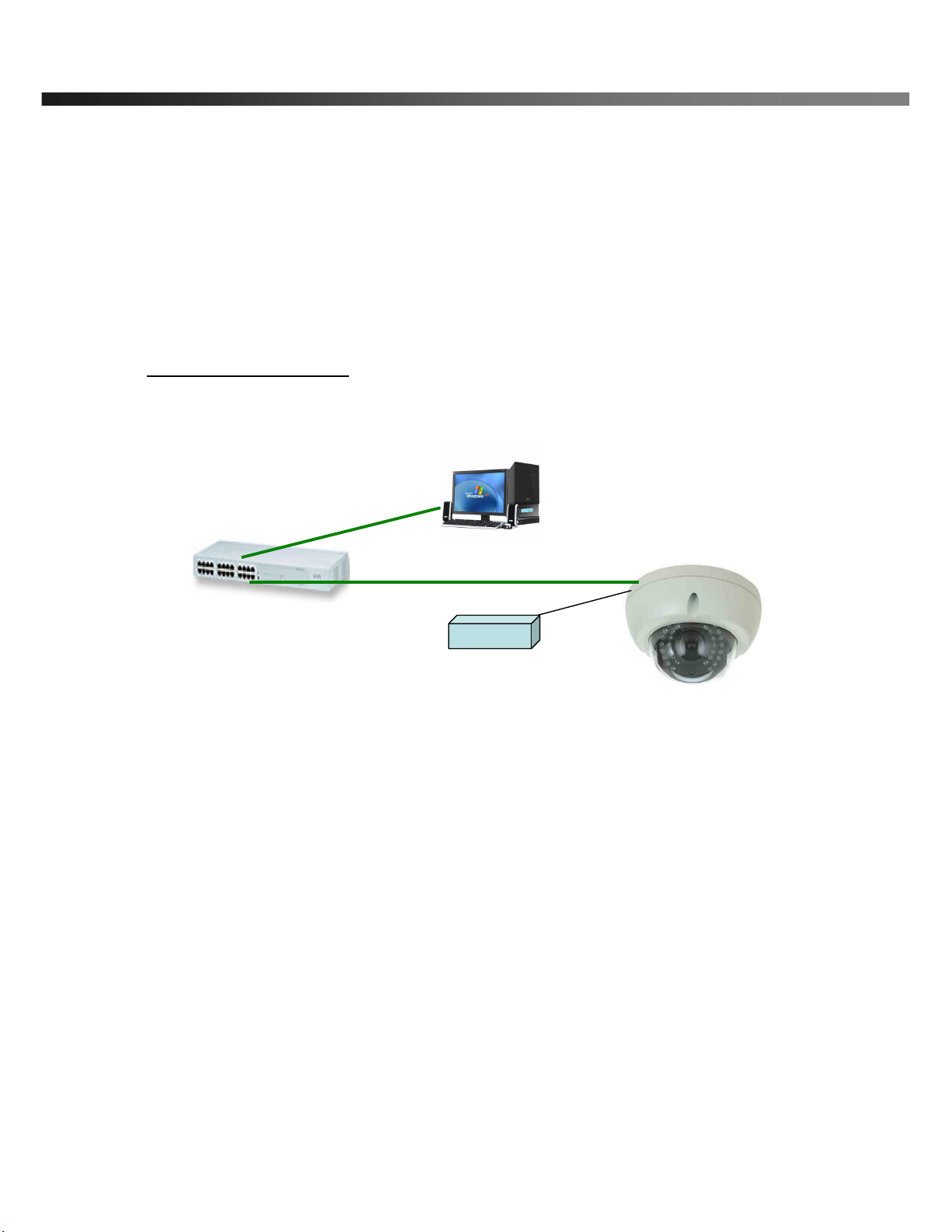
2.6. Quick Installation Guide
Brief information for rapid installation is provided in this section. For more detailed information you are
recommended to refer to pertinent documentations provided with the product or refer to Inscape Data’s home
page (http://www.Inscape Data.com)
1. Apply power to NVC 360 and Connect NVC 360 to LAN like the following picture.
Fig. 2-5 Connecting Network camera and PC
2. Install “IP installer” and “NVR100” on your PC.
Detailed information for installing these programs can be found in [IP-Installer User’s Guide] and
[NVR100 User’s Guide],respectively.
3. Assign IP address to NVC 360 using IP installer.
Identify the type of the network environment and set up IP address. Detailed process of setting up IP
address can be found in [IP-Installer User’s Guide].If network type is xDSL or Cable modem you need
supplementary information provided by your ISP.
4. Connect to NVC 360 in Administrator Mode for initial parameter set-up.
All parameters are set to factory default state when NVC 360 is delivered. You are asked to configure
the system for your environment in administration mode. Detailed information of using administration
mode can be found in [5. Configuring NVC 360 in Administrative Mode]. Among the parameters, the
HUB
DC 12V Adapter

NVC 360 User’s Guide
Rev.0.1 (Dec.2007) 16
parameters in the following table should be set-up with proper values. Detailed information for the
parameters in Administrator Mode is found in [5. Configuring NVC 360 in Administrative Mode]
[Note]: Set-up values are preserved even the power is turned off.
Page Parameter Setup value Factory default value
Video Size
Set the resolution of the video transmitted
from NVC 360.
Max Upload Rate
Set this value smaller than the upload
speed of your network.
Frame Rate
The number of frames to be transmitted per
second.
Basic
Setup
Video Rate
Bandwidth assigned for video transmitted
from NVC 360.
Make sure that you press Check button
to find out the number of maximum
possible simultaneous users then set
the number of users smaller than or
equal to the number.
User
Admin &
Time
Setup
Administrator name
& password
For safety, you are recommended to
change these values from factory default.
For new connection, you need to input
changed values for corresponding fields.
Do not disclose these values to others and
memorize these values.
Default value
User name : root
Password : root
User
Admin &
Time
Setup
Current Time
Input correct time in this field.
Default value :
2001/1/1
5. Connect the input and output signals to NVC 360.
Connectors Function Signal description Number
Mic/LINE-In Audio/Voice in Connect microphone or output from audio
devices. 1
Line Out Audio out for
speaker
Audio from remote site is available from this
connector in bi-directional audio mode.
Connect speaker with amplifier.
1
Connecting Alarm
Sensor
IR sensor, Motion Sensor, Smoke
Detector… 1
Sensor
/Relay Out Connecting Alarm
annunciating
device
Siren, Flashing Light, … 1
Network Network connection
Connect NVC 360 to the network, LAN, 1

NVC 360 User’s Guide
Rev.0.1 (Dec.2007) 17
ADSL or Cable modem.
DC12V Supply DC power Apply DC12V power to network camera 1
6. Remote video connection to NVC 360
Run NVR100 on your PC. Before connecting to NVC 360 it is needed to configure the connection
information on the NVR100. More detailed information of using “NVR100” can be found in [NVR100
User’s Guide].
NVC 360 User’s Guide
Rev.0.1 (Dec.2007) 18
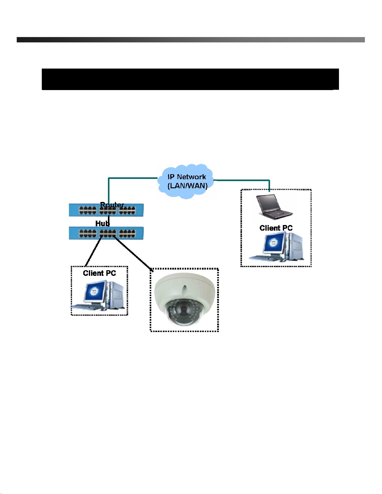
3. Connecting NVC 360 to IP Network
NVC 360 supports LAN, xDSL, and Cable modem. It also supports shared IP environment where single IP
address is shared by at least 2 IP devices. Refer to [IP-Installer User’s Guide] for details of setting the IP
address for NVC 360.
3.1. Connecting to LAN
In case of connecting the NVC 360 to LAN, it is generally connected as in Fig. 3-1.
Fig. 3-1 Connecting NVC 360 to LAN
1. Follow through steps 1 to 3 in Section 2.6 to assign IP address to NVC 360.
2. Check if you can receive video data when connecting to NVC 360 using the viewer program.
4. When one or more IP video products are connected through a IP sharing device (i.e. router) to a larger network
(i.e. the internet), in order to access each unit from outside the local area network, each device must have a
unique RTSP (Real Time Stream Protocol) and HTTP port number. You must also conFig. your IP sharing
device for “port forwarding”. This is to enable the IP sharing device to forward packet data with unique port
number (RTSP and HTTP) to unique internal IP address (local IP address). If you only plan to access multiple
units from within a local area network, you do not need to change the RTSP and HTTP port numbers, unless

NVC 360 User’s Guide
Rev.0.1 (Dec.2007) 19
other IP sharing devices sit in-between the client and the IP video products. For more detailed information
regarding the use of IP sharing device refer to the document [Use of Private IP network using IP-sharing-
device].
3.2. Connecting to xDSL/Cable Modem
1. Please connect NVC 360 to PC through Hub and then connect DC power adapter.
2. Install IP-Installer and NVR100 S/W on PC
3. Using IP Installer S/W, set up some parameters for communication through IP network
Please refer to the IP installer and NVR100 user’s guide.
4. Connect NVC 360 with ADSL/Cable Modem as Fig.3.2
5. Run NVR100 program and check if you can receive video data when connecting to NVC 360.
Fig. 3-2 Connecting NVC 360 to ADSL/Cable Modem
When fixed IP address is assigned to the xDSL or Cable modem, follow the same way as assigning IP
address for the case of LAN using IP-installer. To enable the notification of the changed IP address to the
②
②②
②

NVC 360 User’s Guide
Rev.0.1 (Dec.2007) 20
user over e-mail when the IP address is changed in floating IP environment, you have to assign the e-
mail address when user name and password are input using IP-installer. (Management server provides
a convenient way of connecting to your network camera under dynamic IP environment. Please
refer to the Application note regarding “Management Server” in the CD.)
When connecting NVC 360 to xDSL or Cable modem, usually regular LAN cable is required. But since
some modems have crossover connections, please contact your service provider for detailed
information.
Table of contents
Other Inscape Data IP Camera manuals


