Insta-Chain Insta-Chain Operating instructions

Maintenance &
Troubleshooting Guide
Revision May 2018
44201 Rev E 20-Sep-18

Table of Contents
Sections Page
1. Regularly Scheduled Maintenance 1
2. Troubleshooting 2
3. Diaphragm Replacement 3
4. Chain Wheel Installation and Alignment 4-7
a. Standard Chain Wheel Fig. D
b. Adjustable Pivot Chain Wheel Fig. D-2
c. Installation and Tolerance adjustment 6-7
5. Fastening Torque Sheet 8
6. Warranty 9

1
Regular Scheduled Maintenance
Regularly scheduled maintenance is highly recommended to ensure that your Insta-Chains last
years longer, even the life of your truck. Like any other mechanism the more that you service it
and care for it, the longer it will last.
1. You should perform regular maintenance, year round, by greasing all grease ttings. This
should be checked whenever you have your scheduled maintenance on the vehicle,
or once a quarter.
2. In the summer months: Remove the Chain Wheels, this will help to reduce stress and fatigue on
the arm pivot joint, the brackets, and the spring inside the air can. It will also help to
reduce unnecessary vibration. Unbolt the one bolt that attaches the Chain Wheel to the
Arm (NOTE: Make note where the spacers are placed so the Wheels can be reinstalled
properly later). When reinstalling the Chain Wheel in the Fall you should need to use
a brand new Chain Wheel Nut (P/N: 5211) as it would no longer be able to “lock”. We rec-
ommend replacing the Chain Wheel Bolt (P/N: 5222 for the regular bolt or P/N: 7004 for the
adjustable Wheel Pivot Bolt) as well. If the Chain Wheel Bolt is the Pivot Style leave the
Pivot Bolt in place to maintain the wheel angle. In addition, wrap the threads with tape to
protect them from debris and damage during the summer.
3. Check to make sure that all Bolts and Nuts are tight and within Torque Spec (See Page 8 for
a Torque Chart). This should also be done once a quarter. BOLTS SHOULD NOT BE
TIGHTENED TO TORQUE WITH AN AIR GUN OR AIR WRENCH. YOU MUST
USE A TORQUE WRENCH. FAILURE TO TORQUE PROPERLY WILL VOID YOUR
WARRANTY. If you use an air gun/ air wrench and not a wrench and torque wrench, you
run a great risk of over-torquing and stretching the bolts which will cause the bolts to
loosen and break which could cause the Chain Unit could fall o the truck. Under-torquing
will cause the bolts to shear o.
4. Check all airlines and air tanks for buildup of moisture, even with dryers built into the trucks
systems this can occur. Moisture will freeze in the airline clogging it and freeze in the
solenoid causing it to fail. Grit can also get into the solenoid and can also cause it to fail.
5. If you encounter problems with the exhaust lter on the solenoid clogging up you can replace
the lter with a 90 degree elbow and a piece of airline. Run the airline up along the inside
of the frame rail of the truck where it will stay dry and can vent without collecting water and
grit.
6. The solenoid valve should be actuated periodically to keep it clean and functioning properly.
7. Due to the high spring tension of the return spring, disassembly of the Insta-Chain air cylin-
ders should only be done by qualied personnel. Insta-Chain recommends you send the air
cylinder to the Insta-Chain factory for repair.

2
Diaphragm Replacement
CAUTION: The Air Cylinder contains a HIGH TENSION SPRING
There are two ways to replace the diaphragm. The rst, which we RECOMMEND, is to leave the unit
together. The second is to remove the Air Can and place it in a press. Below you will nd the
instructions for each.
Remove the Dust Boot Clip. Pull the
Arm down, then, pull the Dust Boot
back. Next Place a vice grip on the
Extension Coupling as close to the
Cylinder as possible. (NOTE: It is
would be a good idea to secure the
arm by secondary means as a precau-
tion by tying or strapping it down).
1. Leave the Air Cylinder on the Chain Unit WITH THE BALL JOINT CONNECTED TO THE ARM.It
is critical that you leave the Extension Coupling and Ball Joint attached to the Arm.
Release the Vice Grip and retract the arm
carefully. Replace the Dust Boot Clip.
Test the Chains.
Remove the Clamps and Air Lid.
Replace the Diaphragm.
Replace the Clamps and alternate
tightening so they will do so evenly.
Leave about 1/4” (6-7mm) between
the Clamp legs.
2. Remove the Air Cylinder from the Chain Unit. Place it in a press, remove the clamps, and then
release the pressure. Place the new diaphragm in place, and press the can together. Replace the
clamps, tightening them evenly, alternating. Leave about 1/4” space between the clamp legs.
Replace the Air Can on the Chain Unit and test the Chain Unit.
CAUTION: DO NOT ATTEMPT TO DISASSEMBLE THE AIR CAN
WITHOUT IT BEING ATTACHED TO THE ARM & BALL JOINT OR IN A
PRESS. IT COULD CAUSE SERIOUS INJURY.

Troubleshooting
The following are troubleshooting tips that you can pursue before calling in for further
help.
Chain Wheel
1. Insucient chain throw is due to incorrect mounting, adjustments or worn out chain
links. Check the angles and measurements of the Chain Wheel according to
the mounting instructions.
2. Excess chain wear is due to using the Insta-Chain on bare pavement, or thin snow
or ice. Excess chain wear can also occur if the Chain Wheel is mounted too
low, below 3” or misalignment.
3. Excessive wear on the wheels is due to improper Chain Wheel angles or from the
wheel not being lined up on the centerline of the tire. Re-check these
measurements when this occurs.
4. Excessive wear may also occur from excessive speed.
Arm
1. If the arm of the Chain Unit is hanging down loose and can be moved freely and
you cannot engage or disengage the Chain Units, the spring or pushrod is
most likely broken and will need to be replaced (See the Regular Scheduled
Maintenance item 7).
2. If the arm is stuck down or up and doesn’t respond when activated or deactivated,
please check one of two things:
A. Solenoid Valve
i. There may be grit or water in the solenoid valve. To retract the arms try
tapping on the solenoid valve to knock it loose if you can reach it, be
careful to stay out of the way of the arms retracting, they will come up
fast.
ii. If tapping on the solenoid doesn’t work, try prying the arm, or knocking
it loose to raise it up. IF YOU DO THIS STAY CLEAR OF THE
ARM, DO IT FROM THE OPPOSITE DIRECTION OF THE SWING
OF THE ARM.
iii. Activate and deactivate the Chain Unit and listen for it activating and
deactivating. If you don’t hear it clicking open and closed then it is not
receiving power. Check the wiring with a voltage meter to conrm
this.
B. Arm Bearings
i. The arm bearing may be frozen. One way to check is to remove the Air
Can nuts and remove the can. If the arm is still dicult to move then
it is the arm bearings. Replace them. If the arm bearings move freely,
then there is a problem with the cylinder or solenoid.
3

FIG. D1
FIG. D2
4
Standard Chain Wheel
Adjustable Chain Wheel

5

1. Make sure that the Chain Wheel is LEVEL front to back (check with an analog or digital
angle finder, do not eyeball it or use a bubble level). The wheel may tilt towards the rear of
the vehicle 1° – 2°, but NEVER to the front of the vehicle (see Figure I). There are two ways
to adjust this angle depending on the mounting system of the Chain Wheel.
a. If the arm on your Insta-Chain unit has two holes in the end of the arm and is not
adjustable, you may add or remove washers from between the Mounting Bracket and
the Coupling Nuts on either the front or rear U-bolts. A good rule of thumb is that one
flat washer (1/8” thick) will level the bracket by one degree.
b. The other method is for Chain Units with an Adjustable Pivot Joint for the Chain
Wheel. With this system you would loosen the two 3/8” bolts on the end of the arm
and adjust to spec. Then retighten to Torque, DO NOT USE AN IMPACT GUN OR
WRENCH, if you over torque the bolts it will cause them to break and you will lose
the Chain Wheel. (See Torque Chart on Page 8 \ P/N 5135).
2. The Chain Wheel should tilt towards the tire 8° - 15°(see Figure F). Swiveling the unit side
to side will change this operating angle. This will also affect the clearance between the
Chain Wheel and the Drive Shaft/ Differential. If you have an Adjustable Wheel Pivot joint
on your arm this can also be adjusted there.
3. The wheel should press tightly against the tire. If it is not tight against the tire, you can either
swivel the unit inboard and it will increase the tire pressure, or you may adjust the Extension
Coupling out. The Extension Coupling is the hex rod protruding from the air cylinder that
connects to the ball joint. To adjust the Extension Coupling:
a. Activate the Chain Unit.
b. Remove the Clip from the Dust Boot and pull the Dust Boot up over the Jam nut.
c. Loosen the Jam Nuts on either side of the Extension Coupling and turn the
Extension Coupling counter clockwise for more pressure and clockwise for less
pressure.
d. Deactivate the Chain Unit, then pull the Dust Boot back down over the Jam Nut and
replace the Clip.
4. With the Chain Wheel in the engaged position, grab the Chain Wheel and rub it back and
forth against the tire in order to make the small mark on the sidewall. This mark well be
about ½” high and 1” long (See Figure I).
FIG. I
6

5. The center of the mark should hit the tire at the bulge, 3”-4” off the ground (see Figure F or
I). This may be changed by adding or removing Chain Wheel Spacers between the arm and
the Chain Wheel. These Chain Wheel Spacers are 3/8” thick. If the vehicle is an empty truck
that will normally be hauling a lot of weight (i.e. over-the-road hauler, dump truck, or fire
pumper) you will want to try to keep this measurement 3 ½”-4” off the ground because of the
squash in the tires when the vehicle is loaded. For vehicles with 16” tires, this measurement
will need to be between 2 ¾”-3” because the bulge sits lower. The Chain Wheel needs to hit
at the bulge of the tire. NOTE: if you are mounting the chains on a bare chassis this
measurement needs to be 4”-4 ½” off the ground because the weight of the body will drop
the height of the Insta-Chains slightly.
6. Now check to see if the wheel mark is at the centerline of the tire, this is very critical to
ensure the proper throw of the chains. The truck must be on the ground to ensure proper
measurement.There are two methods for accurately finding the centerline:
a. Take a plumb line and hang it from each side of the tire rim. With a piece of chalk,
make a small mark on the tire where the plumb line hits the sidewall. Measure the
distance between these two marks (R in Figure I). Divide this measurement in half
and measure this distance in from one of the plumb line marks (R/2 in Figure I).
Make a small chalk mark at this point. This is the centerline of the tire and axle. For
example, an 11R-22.5 tire has an outside rim measurement of 23 ½”; half of this is
11 ¾”. This means that the centerline is 11 3/4” from one side of the rim.
Now draw vertical line on the tire. The center of the Chain Wheel mark must be lined
up with the centerline of the tire. It may be up to ¼” behind the centerline but NEVER
in front of the centerline.
b. Use a Digital Level placed inside the rim. Place the level on the ground and zero it
out. Then place the level inside the rim and find the center of the tire, this will be the
centerline of the tire/ axle. Hang a plumb line down to make a mark at the bulge of
the tire.
If you have a Universal Mounting Bracket you can adjust the unit so that it hits on centerline
by loosening the two Mounting Tube Flange Bolts and push the unit forward or backward so that
the Chain Wheel hits the center of the tire.
If you have a fixed Mounting Bracket or a 3 Coupling Nut Style bracket, you can try adjusting
this in the two mounting holes where the Chain Unit attaches to the Mounting Bracket.
7. Each chain strand has 10 links of chain for trucks with 19.5 tires and larger. If the strands
drag on the ground in the disengaged position, you may cut 1 link off each strand. DO NOT
REMOVE MORE THAN 2 LINKS OF CHAIN. On vehicles with 16” tires you only have 8
links of chain, DO NOT REMOVE LINKS. There must be a minimum of 9 links (8 links for
16” tires) for the Insta-Chains to work effectively. If they are still dragging on the ground or
are close enough to the ground to cause undue wear, Insta-Chain sells a Chain Tray to
raise the chains off of the ground.
7
DRY
TORQUING
FT/LBS
LUBRICATED
TORQUING
FT/LBS
5211-W M20x2.5 Nut GRD 8 Chain Wheel Nut
5438 M10x2.0 Nylon Nut Ball Joint Nut
5134 M14x1.5 Nut Extension Coupling Jamb Nut
4613 3/8"-24 Lock Nut Chain Plate Nut
5207 3/8"-24 Lock Nut Air Cylinder Nut
5409-T 3/8"-16 Nylon Nut Air Cylinder Clamp Nut
5130-B 3/8"-16 Lock Nut Stop Bolt Nut
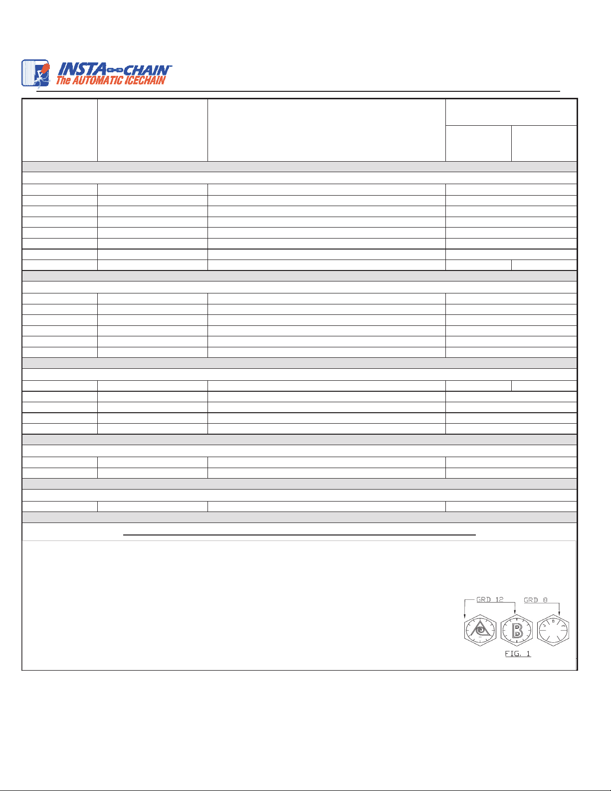
5135 3/8"-16x1 3/4 GRD 12 Bolt Ball & Socket Arm Bolt 60 45
0226 5/8"-11 GRD 8 Mounting Hole Lock Nut
0250 5/8"-11 x 2 1/2" GRD 8 Mounting Hole Bolt
Varies by Length 5/8"-11 GRD 8 Coupling Nut Bolt
0226 5/8"-11 GRD 12 Mounting Hole Lock Nut
90250 5/8"-11 x 2 1/2" GRD 12 Mounting Hole Bolt
Varies by Length 5/8"-11 GRD 12 Coupling Nut Bolt (Heavy Duty See Fig 1)
Varies by Size OEM U-Bolt Size Coupling Nut (When installed underneath original OEM nuts) 130 100
Varies by Size OEM U-Bolt Size Coupling Nut (When OEM nuts are removed and replaced)
Varies by Model 1"-14 Bolt GRD 8 Bar-Pin Mounting Bracket
Varies by Model 3/4"-16 U-Bolt GRD 8 U-Bolt Saddle Mounting Bracket
Varies by Model 5/8"-18 U-Bolt GRD 8 U-Bolt Saddle Mounting Bracket
5206 1/4"-20 Lock Nut Solenoid Mounting Nut
5406 1/4"-20 Bolt Solenoid Mounting Bolt
No P/N Vehicle U-Bolt OEM U-Bolts Replacement
MUST READ IMPORTANT TIPS FOR INSTALLING INSTA-CHAIN PRODUCTS
See OEM Torque Specs
185
128
128
175
MOUNTING CONFIGURATION HARDWARE SPECS (See FIG.1 for Hardware Identification)
130
312
See OEM U-Bolt Specs
See OEM Bar-Pin Specs
CHAIN UNIT HARDWARE
135
45
135
SOLENOID SYSTEM HARDWARE
35
MOUNTING BRACKET HARDWARE SPECS (See Fig 1)
OEM U-BOLTS
5 lbs or (50 in/lbs.)
175
75
45
30
5 lbs or (50 in/lbs.)
TORQUE SHEET
NOMINAL TORQUING
FT/LBS
INSTA-CHAIN DESCRIPTIONFASTENER DETAILS
INSTA-CHAIN
PART NUMBER
30
1.) Insta-Chains coupler nuts are required to be fastened underneath OEM U-bolt nuts with an Anti-Seize.
2.) Mounting bracket bolts are required to have high strength locking fluid when fastening bracket to its fixture.
3.) ALL NUTS can only be re-used and fastened THREE times (otherwise the lock nut will lose its locking set.)
4.) Always tighten bolts in cross patterns and in 1/2 torque stages until the appropriate torque is reached.
5.) All OEM U-Bolts should be fastened by using the OEM specs of torquing.
6.) Never exceed torque specs over 5% this will result in stretched bolts.
7.) Lubricated Torquing is defined as fastening a nut or bolt by using a thread locker or Anti-seize.
(Anti-Seize is to be used on all through pins, coupling nuts, and U-bolts when fastening.)
8

Warranty
The Insta-Chain system is warranted to be free from defects in material for one (1) year
from the date of purchase, or 50,000 miles, whichever comes rst, when used for the purpose
intended under normal conditions, except the solenoid valve, which is guaranteed for 90 days.
If it has been past 90 days, Insta-Chain will try to obtain a manufacturer’s warranty, but can-
not guarantee any warranty replacement. This warranty does not include the following: freight
charges, labor to replace the defective part, normal wear on the chains or chain wheels, failure
to grease the wheel or arm bearings, or any problems resulting from improper installation of the
Insta-Chain on the vehicle. Damage resulting from road debris, potholes, curbs, rocks or other
things that could hit and damage the chain unit is also not included. Insta-Chain reserves the
right to inspect the parts to determine whether to repair, replace, or return the damaged parts.
Defective parts must be returned to Insta-Chain for warranty inspection. Abuse or misuse, in-
cluding operating the Insta-Chains while driving over 30 mph, VOIDS any warranty.
9
Table of contents


