Instant Burger A975 Building instructions
Broaster Company
2855 Cranston Road, Beloit, WI 53511-3991
608/365-0193 broaster.com
© 2017 Broaster Company
Printed In U.S.A.
Instant Burger ® is a registered trademark.
Be sure ALL installers read, understand, and have access to this manual at all times.
Design Certified By:
UL, CUL & NSF
SERVICE AND PARTS MANUAL
MODEL A975
Manual #17925 5/17 Rev: 1/23

W-1
All adjustments and repairs shall be made
by an authorized Broaster Company repre-
sentative.
If there is a power failure, turn power switch
OFF.
Failure to read and
understand this manual
completely could result in serious injury
or death. Be sure ALL operators read,
understand and have access to this
manual at all times.
Rags or paper containing
cooking oil can catch fire
if exposed to heat. Laundering will not
remove the oil. Dispose of all oil-soiled
papers and rags in a trash container that
is in a ventilated area away from all
cooking equipment or other heat
sources such as direct sunlight.
DO NOT clean this unit
with a water jet. Use of
this cleaning method could result in
serious injury or death.
FOR YOUR SAFETY
Do not use or store gasoline or other flammable vapors
or liquids in the vicinity of this or any other appliance.
Improper installation, adjustments, alteration, service or maintenance can cause
property damage, injury or death. Read the installation, operating and mainte-
nance instructions thoroughly before installing or servicing this equipment.
For the sake of safety and clarity, the following words used in this manual are defined as follows:
Indicates an imminently hazardous situation which, if not avoided, could
result in serious injury or death.
Indicates a potentially hazardous situation which, if not avoided, could
result in serious injury or death.
Indicates a potentially hazardous situation which, if not avoided, could
result in minor injury, property damage or both.
broaster.com Manual #17925 5/17


i
TABLE OF CONTENTS
1. - WARNING LABELS ................................................................................ 1 - 1
2. - ELECTRICAL SUPPLY ........................................................................... 2 - 1
3. - CONTROL PANEL .................................................................................. 3 - 1
COMPONENT DESCRIPTIONS ......................................................... 3 - 1
ACCESS FOR SERVICE ......................................................................................... 3 - 2
CONTROLLER .................................................................................... 3 - 3
CALIBRATION SETTING CHECK ....................................................... 3 - 4
QUICK FUNCTION TEST .................................................................... 3 - 5
FULL FUNCTION TEST ...................................................................... 3 - 5
TRIACS ................................................................................................ 3 - 7
TRIAC TESTING PROCEDURE ..................................................... 3 - 7
REPLACEMENT ............................................................................. 3 - 8
TERMINAL BLOCK REPLACEMENT ................................................. 3 - 8
4. - TROUBLESHOOTING ............................................................................ 4 - 1
5. - PARTS
OUTER PANELS AND PARTS ........................................................... 5 - 1
POWER MODULE ............................................................................... 5 - 2
CONNECTOR BLOCK ASSEMBLY ..................................................... 5 - 3
PARTS LIST .......................................................................................... 5 - 4
SERVICE NOTES
broaster.com Manual #17896 6/17


1 - WARNING LABELS
1-1
broaster.com Manual #17925 5/17
THIS PAGE PROVIDED FOR FUTURE USE ONLY


2 - ELECTRICAL SUPPLY
2-1
broaster.com Manual #17925 5/17
ELECTRICAL CHARACTERISTICS:
This unit is designed to operate on a
grounded 120V, 30 Amp, 1 phase dedicated
line. The Instant Burger® will stop operating
if the voltage drops below 90 volts.
DO NOT connect to a cir-
cuit rated less the 30 amps.
2-2
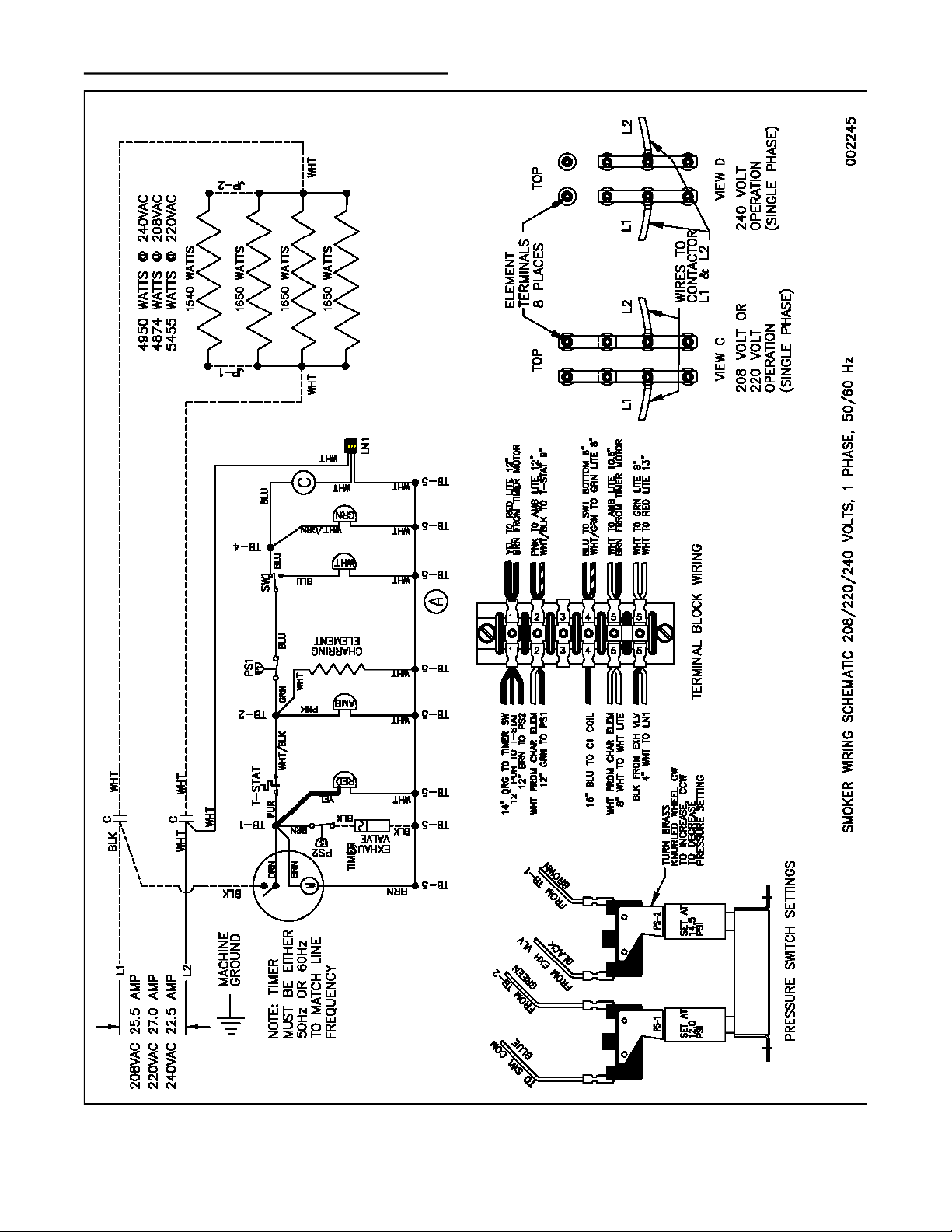
WIRING DIAGRAM:
broaster.com Manual #17925 5/17

3 - CONTROL PANEL
3-1
2020 CONTROL MODELS
POWER SWITCH: Applies power to the
unit.
GREEN READY LIGHT: Indicates unit is on
AMBER LIGHT: Illuminates when a cook-
ing cycle is in progress.
COOK BUTTON: Push to start a cooking
cycle.
When the COOK button is
pushed the green READY
light goes off and the amber light comes
on. When the cooking cycle is done the
amber light goes off and the green
READY light illuminates again.
COOKING MODE SETTING: Select cook-
ing mode 1 or cooking mode 2 as required.
The green light above either button will indi-
cate which cooking mode is active.
broaster.com Manual #17925 5/17

3 - CONTROL PANEL
3-2
CONTROLLER (PC BOARD)
Before removing the PC
board perform the full
function test (see page 3-7) to determine
if the board needs to be replaced.
Controller Replacement:
1. Disconnect the wires from the switch
and plates.
2. Remove the (4) mounting screws from
the board.
3. Carefully remove the board by pulling
it straight back.
6. Install the new PC board in reverse
order.
7. Perform the Calibration Setting Check
and either the Quick Function Test or
the Full Function Test.
broaster.com Manual #17925 5/17

3 - CONTROL PANEL
3-3
broaster.com Manual #17925 5/17
POWER SWITCH: Applies power to the
unit.
GREEN LIGHT: Indicates unit is on
AMBER LIGHT: Illuminates when a cook-
ing cycle is in progress.
RED BUTTON: Push to start a cooking cy-
cle.
When the red START but-
ton is pushed the green
light shuts off and the amber light illumi-
nates. When the cooking cycle is done
the amber light shuts off and the green
light illuminates again.
COOK MODE SWITCH: This switch con-
trols the cooking time relative to the type of
meat being cooked.
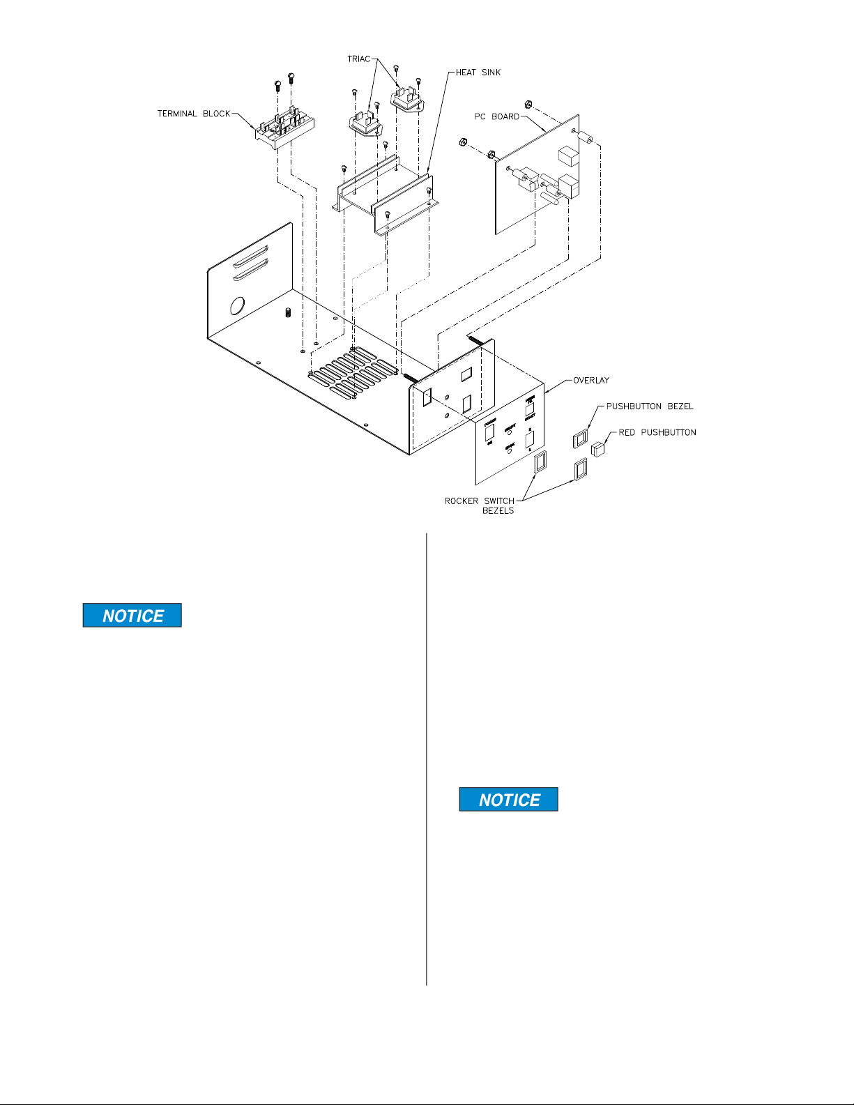
The switch actuators and
the lights are part of the PC
board inside the power supply module.
The bezels around the
switches are not removable
from the front of the unit with the power
module installed.

3-4
ACCESS FOR SERVICE
1. Unplug unit from power source.
2. Turn unit over on it’s top and remove
screws shown at arrows.
3. Lift power module partially out of unit
and disconnect black and white wires
from connector block cord.
4. Remove power module from unit.
broaster.com Manual #17925 5/17
3-5
CONTROLLER (PC BOARD)
Before removing the PC
board perform the full
function test (see page 3-7) to determine
if the board needs to be replaced.
Controller Replacement:
1. Unplug the wire connector with the (4)
thin wires located at the bottom center
of the board.
2. Disconnect one end of the wire going
through the coil on the PC board
located in the lower left corner of the
board.
3. Pull off the red start button and set it
aside.
4. Remove the (3) mounting nuts from the
board.
5. Carefully remove the board by pulling
it straight back until the switches and
lights are clear of the front of the
power module.
6. Install the new PC board in reverse
order.
7. After reconnecting all of the wires,
check PC Board wiring with diagram
on page 2-2.
Be sure the large black
wire goes through the
hole in the coil on the new controller.
8. Perform the Calibration Setting Check
and either the Quick Function Test or
the Full Function Test.
broaster.com Manual #17925 5/17
3-6
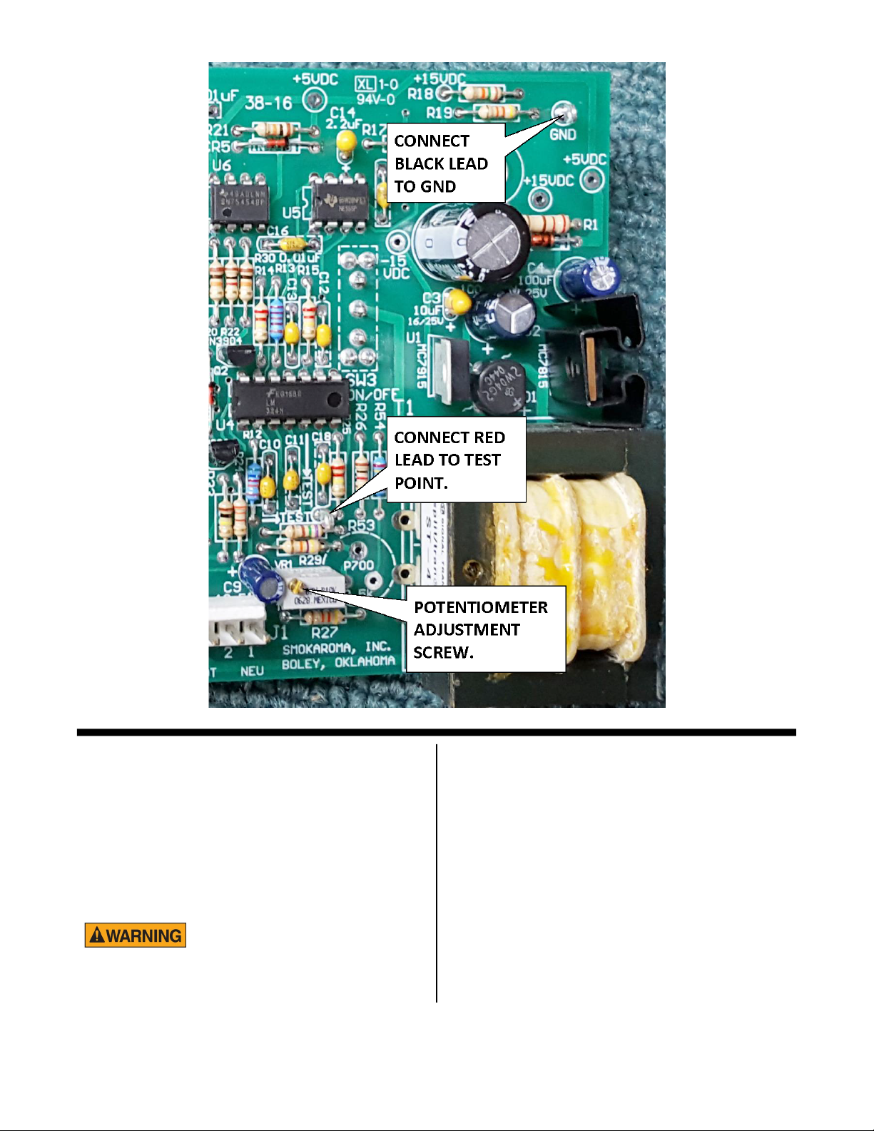
CALIBRATION SETTING CHECK:
1. See ACCESS FOR SERVICE.
2. Connect voltmeter leads as shown
above and set meter to read VDC.
3. Plug power module into power source.
Be careful, potential shock
hazard exists.
3. Turn power on switch to on. Voltmeter
should read +0.29 ±.005 VDC.
4. If adjustment is required use a small
screwdriver and turn the screw on the
top of the potentiometer to adjust.
5. Unplug power module.
6. Reconnect black and white wires from
connector block cord.
7. Insert power module into unit and rein-
sert screws. Make sure the feet are
mounted as shown in the picture on
page 3-2.
broaster.com Manual #17925 5/17

3-7
8. Turn unit right side up, plug unit to
power source and perform Function
Test.
QUICK FUNCTION TEST:
Perform calibration set-
ting check before doing
this test.
1. Plug in unit and turn on.
2. Open cover and insert the leads of the
voltmeter into the connector block as
shown below.
The red and black leads
can be in either side of
the connector block. You will have to
hold the leads in place while this test is
being conducted.
3. Press the START button and the
amber light should come on and stay
on for 10 seconds minimum. The volt-
meter should read line voltage.
4. Turn unit off then back on. The green
light should come on and the voltme-
ter should read zero at the connector
block.
5. If the unit performs this test satisfacto-
rily, then the unit is ready to operate.
FULL FUNCTION LOAD TEST:
The "Load Test" is a better test than the
"Quick Check" as it provides a definite test
as to whether the board and the Triacs are
working.
The equipment needed is a hair dryer of
about 1800 watts. This will put a load on the
machine of about 16 amps, which is just a
little less than amperage draw when
cooking a 3.2 ounce hamburger. The hair
dryer must have a switch with "High,"
"Medium," "Low" and "Off ', in that
sequence.
There are two tests.
First you need to adapt the plug-in of the
hair dryer such that i t will mate with the
power connector block of the Instant
Burger. This may be done by attaching two
#12 solid wires (the type used in house
wiring) on each end as follows.
Strip one end on each wire back 3/4 of an
inch. Strip the other end 1/4 inch. Place
yellow slip on connectors on 1/4 inch end of
wire and then crimp. Place yellow slip-on
connectors on the blade of the dryer plug.
You may have to grind down the blades for
the yellow connectors to fit.
FIRST TEST: This test allows you to test the
COOK MODE “1” circuit.
broaster.com Manual #17925 5/17

3-8
To run this test:
1. Set the COOK MODE switch to “1”.
2. Insert the 3/4 inch bare ends into the
power connector block, one in each
side, of the Instant Burger. (Omit
steps 4 & 5, if the unit does not have
a "Rare Well-Done" knob on the
control.)
3. Place the switch on the hair dryer to
"High ."
4. Place the "Rare Well-Done " Knob in
the "Rare " position. Press the "Start"
button. The hair dryer should start
running. It should stay on
approximately 5 seconds and then
automatically cutoff by itself.
5. Turn the "Rare Well-Done " Knob to
the full "Well-Done " position.
6. Press the red "Start" button, the hair
dryer should come on and stay on for
at least 10 seconds. (You should count
to 10 because, if you attempt to turn it
off prematurely during the time, the 5-
second timer is still energized and it
will not cut off)
7. After counting to 10, slide switch on
the hair dryer to “Medium.” The amber
light on the control board should shut
off and the hair dryer should stop
running immediately. If it does, the
board is functioning properly on cook
mode setting “1” and the Triacs are
functioning properly.
If the dryer comes on immediately without
pressing the start button and the green light
is in the ready position, the Triacs are bad.
Go to “Triac Test” to find and replace the
defective Triac(s). If the dryer will not
operate when the “Start” button is pushed,
the board is most likely defective. Replace
it.
SECOND TEST: This test tests the COOK
MODE “2” circuit.
To run this test:
1. Set the COOK MODE switch to “2”.
2. Switch the hair dryer to “High”.
3. Press start button. The hair dryer
should run.
4. Time for approximately 10 seconds
and then slide the switch to “Medium.
There should be a slight delay in time
that you switch the hair dryer to
"Medium" and the time that the amber
light goes out and the hair dryer will
stop.
If it occurs, the control board is working
fine. and the Triacs are working fine.
You may also adapt the hair dryer to check
the control box by itself. This may be done
by attaching a #12 solid wire to each blade
of the hair dryer male plug. Install a yellow
slip-on connector to each end of both
wires. Connect one end of each wire to the
hair dryer plug, and the other end of each
wire to the terminal block where the wires
to the connector block would normally be
connected.
broaster.com Manual #17925 5/17
3-9
TRIACS:
See ACCESS FOR SERVICE on page 3-2.
It is recommended to test the triacs before
replacing them.
TRIAC TESTING PROCEDURE:
Unplug from power
source and disconnect all
wires from the triacs.
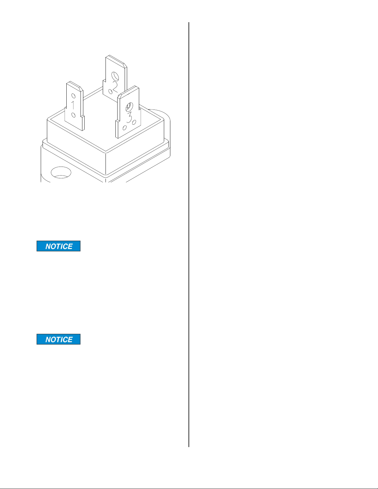
1. Align Triac with small terminal toward
you. Set ohmmeter to lowest setting
(probably 200 OHMS). Terminals are
labeled “1”, “2”, and “3” with small
terminal as “1” and continuing
clockwise.
The numeral “1”, “2”, “3”
are not marked on the
Triac, but are used just to identify the
terminals as shown above.)
2. Perform the next (3) tests on each
triac.
Test A - Place ohmmeter leads on
terminals 1 & 2 (see above). The meter
should indicate continuity.
Continuity - Good
No continuity - Bad
Test B - Place the ohmmeter leads on
terminals 1 & 3 (see above). The meter
should NOT indicate continuity.
Continuity - Bad
No Continuity - Good
Test C - Place the ohmmeter leads on
terminals 2 & 3 (see above). The meter
should NOT indicate continuity.
Continuity - Bad
No Continuity - Good
3. If the Triac tests “bad” in any one of
these 3 tests, the Triac is bad, replace
it and discard the bad triac.
NOTES:
A. Older Triacs (slotted screw hole, one
end), “Continuity” meter reading on
test A “good” will read about 28
OHMS.
B. Newer Triacs (round hole, both ends),
“Continuity'' meter reading on test A
“good” will read about 62 ± 5 OHMS.
C. “Continuity” meter readings on “bad”
may be anything, but it is generally
about 200 OHMS.
D. “No Continuity” meter reading will
generally read “OL” on newer meters
and “T” on older meters.
E. This method of testing Triacs is very
effective in determining a defective
Triac when the symptom is “cooking
all the time”. However, it will not deter-
mine all the defects in a Triac. When
trouble persists, replace both Triacs.
broaster.com Manual #17925 5/17

3-10
TRIAC REPLACEMENT:
1. Disconnect all wires from the triac
being replaced.
2. Remove mounting screws, lift off old
triac and discard.
3. Apply a small amount of Heat Sink
Compound to the metal side of the
new triac.
4. Mount new triac with the screws
removed in step 1 making sure the
small terminal is toward the PC Board.
5. Check triac wiring with diagram on
page 2-2.
TERMINAL BLOCK REPLACEMENT:
See Access For Service on page 3-2.
1. Disconnect the wires from the power
cord.
2. Remove the (2) mounting screws.
3. Lift the terminal block up and out of
the way.
4. Mount new terminal block using the (2)
screws removed in step 2.
Make sure the resistor on
the new terminal block is
on the left side of the power module as
you look at it from the controller end.
5. Move the wires from the old terminal
block to the same terminal on the new
terminal block.
broaster.com Manual #17925 5/17
Other manuals for A975
2
Table of contents
Popular Commercial Food Equipment manuals by other brands


Diamond
Diamond AL1TB/H2-R2 Installation, Operating and Maintenance Instruction

Salva
Salva IVERPAN FC-18 User instructions

Allure
Allure Melanger JR6t Operator's manual

saro
saro FKT 935 operating instructions

Hussmann
Hussmann Rear Roll-in Dairy Installation & operation manual

Cornelius
Cornelius IDC PRO 255 Service manual

Moduline
Moduline HSH E Series Service manual

MINERVA OMEGA
MINERVA OMEGA DERBY 270 operating instructions

Diamond
Diamond OPTIMA 700 Installation, use and maintenance instructions

Diamond
Diamond G9/PLCA4 operating instructions

Cuppone
Cuppone BERNINI BRN 280 Installation

Arneg
Arneg Atlanta Direction for Installation and Use