Instant Upright Spandeck 500 User manual

Spandeck 500 Bridged Tower
ASSEMBLY MANUAL
DESIGNATION
BS 1139-6:2014
EN1004
CEN 1298 –IM - en
SPAN 500 BRIDGED TOWER
Date: 08/11/18
Rev. 5

Page 2 of 38
SPAN 500 BRIDGED TOWER
CONTENTS
DESIGN CRITERIA ................................................................................................................................................3
ASSEMBLY PREPARATION...................................................................................................................................4
USAGE ADVICE ....................................................................................................................................................5
MOVING TOWERS...............................................................................................................................................5
ASSEMBLY, USE & DISMANTLING.......................................................................................................................6
CARE AND MAINTENANCE..................................................................................................................................6
3-T SAFETY STANDARD –THROUGH THE TRAP ..................................................................................................6
ANCHORS, TIES & BALLAST.................................................................................................................................7
USE OF PREFABRICARTICATED SCAFFOLDS FOR ACCESS TO ADJACENT STRUCTURES ......................................7
CARE AND MAINTENANCE..................................................................................................................................7
TOWER CONFIGURATION (6m TOWER) .............................................................................................................8
PART LIST ............................................................................................................................................................9
Tower Parts List ......................................................................................................................................... 9
Spandeck Parts List .................................................................................................................................. 10
TOWER SELF WEIGHT (SW) AND TOWER LEG LOAD ........................................................................................10
6m ASSEMBLY PROCESS ...................................................................................................................................11
5m ASSEMBLY PROCESS ...................................................................................................................................24
ALTERNATIVE BUILDS .......................................................................................................................................33
Over an obstruction:................................................................................................................................ 33
Using a single Spandeck........................................................................................................................... 34
USE OF KNEE BRACES WITH SPANDECK ...........................................................................................................36
DISMANTLING / MOVING TOWERS..................................................................................................................37

Page 3 of 38
SPAN 500 BRIDGED TOWER
This tower structure and its components have been designed in accordance with EN1004:2004
and BS1139-6: 2014. The following tables show the permissible loads on the tower.
MAXIMUM SAFE WORKING VERTICAL LOAD
PLATFORM SAFE WORKING LOAD
B x D
275 Kg over two platforms (evenly
distributed)
SPANDECK SAFE WORKING LOAD
C x D
275 Kg over two spandeck (evenly
distributed)
TOTAL SAFE WORKING LOAD ON TOWER
CONFIGURATION
A x D
825 Kg Max.
(evenly distributed)
SAFE WORKING HORIZONTAL LOAD
TOP PLATFORMS OF MAIN TOWER
30 Kg exerted by ONE person only
NO. OF PERSONS ON TOWER
During USE, ASSEMBLY & DISMANTLE
Max. 3 Persons
Per Bay less than 4m in length
Max. 1 Person
Per Bay greater than 4m in length
Max. 2 Persons
DESIGN CRITERIA
B
C
P
D
C
P
B
C
P
C
C
P
A

Page 4 of 38
SPAN 500 BRIDGED TOWER
1.
Preparation
•
Locate the tower level adjusters on each leg at 10cm
(4
inches)from thebottomof theleg.
•
Unlocktheinterlockclipsonallframes.
•
Wheninstalled,alwaysmovetheinterlockcliptothe
“locked”
position.
•
Sort the braces into horizontal and diagonal braces -
the
diagonals are slightlylonger.
•
Unlockthebracelocks.
2.
Base
Step1:Installcastorintoadjustableleg.
Step2:Ensureinterlockclipsarereleasedfromthebase
frames (bottomframes).
Step3:Installcastor/legassemblytoframebypushing the
leg into the frame tube. This should be done with manual
forceonly,notools.
Step4:Lockcastorsbeforeascendinganypartof
the tower.
3.
Locking down the platform (Windlock)
Awindlockclipisinstalledontheplatformatthehook. This
islockedasshownhere.
ASSEMBLY PREPARATION
10cm
Unlocked
Locked
Notethelockingandunlockingposition
forthecastorsasshownhere.
Unlocked
Locked
Unlocked
Locked
Unlocked
Locked

Page 5 of 38
SPAN 500 BRIDGED TOWER
•We recommend a minimum of three people to assemble, dismantle and move the platform tower.
•Check that all components are on site and in good working order.
•
Ensure that the assembly location is checked to prevent hazards during assembly, dismantling or moving
and while working on the tower. Particular attention should be given to the ground condition, whether level
or sloping, obstructions and wind conditions. The ground condition must be capable of supporting the tower
structure.
•
Towers must always be climbed from the inside of the assembly using the ladder.
•
Adjustable legs must only be used to level the tower and leg extension must be minimized before the
tower is moved (max 150mm).
•
Lifting of components must be done inside the effective base area of the tower; components are normally
hoisted using a rope.
•
Moving the tower must only be done by manual effect from the base of the tower.
•
When moving tower be aware of overhead hazards (e.g. electric cables).
•
No personnel or material to be on the platform whilst the tower is being moved.
•
When tying-in the tower, attach a tie to each upright at 4m height intervals. Ensure that couplers are
suitable for 50mm diameter aluminium tube.
•
Do not use boxes or steps to gain additional height. If extra height required, contact your distributor to
get extra components.
•
Do not lift or suspend an assembled mobile tower.
•
Damaged components or components from other tower systems must never be used.
•
Stabilisers should always be fitted when specified. Use the stabiliser shown on the component list
according to the tower height.
•
When wind exceeds Beaufort force 4, cease using the tower.
•
If wind is expected to reach Beaufort force 6, tie tower to a rigid structure.
•
If winds of Force 8 are forecast, dismantle the tower or remove to shelter.
•
Wind speed should not exceed 29km/h (8.1m/s)
•
Ensure leg extension is minimised (Max 150mm). Release the castor brakes.
•
Raise the stabiliser feet only enough to clear obstructions, maximum 25mm.
•
Ensure tower is empty (material and personnel).
•
Check for overhead obstructions including electrical wires.
•
Move the tower manually by applying force at the base –do not use machinery to push or pull the tower.
Once moved –prepare the tower for use, use the pre-use safety inspection checklist at the end of this
manual.
•
Check all castors and stabilisers are in firm contact with the ground.
•
Check tower is vertical (spirit level) and adjust legs as required.
•
Reapply the castor brakes.
USAGE ADVICE
MOVING TOWERS

Page 6 of 38
SPAN 500 BRIDGED TOWER
•
As part of the risk assessment, wind conditions must be considered and reviewed regularly, depending on
the duration the structure is onsite.
•
When wind exceeds Beaufort force 4, cease using the tower.
•
Platform must be installed with vertical distances between them not exceeding 2m when assembling and
dismantling.
•
If wind is expected to reach Beaufort force 6, tie tower to a rigid structure.
•
If winds of Force 8 are forecast, dismantle the tower or remove to shelter
•
Sheets, tarpaulins, cladding or similar, must not be attached to the tower as these will significantly increase
any side loads from wind and will potentially make tower unstable.
•
Beware of wind turbulence, funnelling effect around buildings and updraft on stairways.
•
The maximum allowable side load on a tower is 30kg by one person only.
•
Warning: Excessive side loads due to working from the tower may cause the structure to become unstable.
•
The tower must not be used if there is a risk of lightning strikes.
Wind speed
Force
Peak mph
Peak km/h
Peak m/s
Guidance
4
18
29
8.1
Moderate breeze –raises dust & loose paper
6
31
50
13.9
Strong breeze –difficult to use umbrella
8
48
74
20.8
Gale force –walking is difficult
CARE AND MAINTENANCE
•
Keep all equipment clean, especially spigots
and sockets where frames join. Spigots
should fit easily into sockets. Lubricate with
light oil.
•
Remove dirt or paint from adjustable legs with
a light brush, lightly oil the leg locks.
•
Do not strike or hammer components. Do not
throw or drop onto hard surfaces.
•
Lightly oil spring mechanism of the hooks.
•
For transport and storage, components are
best storedvertically.
•
Damaged parts should be repaired or
replaced. Contact your equipment supplier for
advice.
•
Ensure parts are not damaged by excessive
strapping forces when transported.
•
Refer to the Instant Upright website for a
detailed inspection guide:
www.instantupright.com
3-T SAFETY STANDARD - THROUGH THETRAP
This is an approved method of tower construction
which, if carriedoutbyacompetentperson,
complieswithcurrentsafety legislation.
Construction- basic principles
•
Alwaysinstallthetrapdoorovertheladder(ifoneisfitted).
•
Ensurethetrapdoorhingestotheoutsideofadoublewidth
tower(nottothecentre).
•
Oncetheplatformhasbeeninstalled,climb,usingthe
approvedmethodandsitinthetrapdooropening.
Fig1
•
Whileseated,attachhorizontalbracestotheframestoformguardrailsonbothsidesoftheplatform.
•
Seeassemblyinstructionsforspecificplacementofguardrails.
•
2bracesarenormallyrequiredeachside;althoughbracingframescanbeusedon
theoutsideif desiredorspecifiedintheinstructions.
•
Onlywhentheplatformisfullyguardedisitsafetostandupontheplatform.
Dismantling
•
Unlockthebraceendsfurthestawayfromthetrapdoor.
•
SitthroughthetrapdoorasperFig.1
•
Donotremovebracesuntilsittinginthetrapdoor.
•
NEVER STAND ON AN UNGUARDED
ASSEMBLY, USE & DISMANTLING
3-T SAFETY STANDARD –THROUGH THE TRAP
WARNING
NEVER STAND ON AN

Page 7 of 38
SPAN 500 BRIDGED TOWER
ANCHORS, TIES & BALLAST
This tower has been designed to be self-supporting under the loading conditions set out in EN1004:2005 and
does not require tying in. Tying in should be considered for potential wind conditions if the tower is left
unattended. When used, selected and installed anchors in concrete and masonry must be selected and
installed in accordance with BS8539. This prefabricated tower scaffold has been designed to be properly
secured to a suitable adjacent supporting structure capable of withstanding the forces that will be imposed
upon it by the attachment of the tower. Devices for securing the tower must be simultaneously rigid in both
tension and compression and capable of withstanding and transmitting the loads imposed by the tower to the
supporting structure.
If ballast is necessary, it must be secured in position and made of rigid material such as steel or concrete but
excluding liquid or granular material.
•
Tower must be built on base plates and properly secured to an adjacent supporting structure to prevent
movement of the tower away from the structure at the point of access.
•
There must be no gaps between the platform of the scaffold tower and the place being accessed through
which a person, tools or materials could fall.
•
The platform of the scaffold tower and the surface onto which a person will step when accessing another
place must be at the same level.
•
Means of protection must be removed only for the time and to the extent necessary to gain access or egress
or for the performance of a task and must be replaces as soon as practicable.
•
The task must not be performed while means of protection are removed unless effective compensatory
measures are in place.
•
Provision must be made to prevent falls –not only from the prefabricated tower scaffold, but also from the
adjacent structure.
CARE AND MAINTENANCE
•
Keep all equipment clean, especially spigots and sockets where frames join. Spigots should fit easily into
sockets. Lubricate with light oil.
•
Remove dirt or paint from adjustable legs with a light brush, lightly oil the leg locks.
•
Do not strike or hammer components. Do not throw or drop onto hard surfaces.
•
Lightly oil spring mechanism of the hooks.
•
For transport and storage, components are best stored vertically.
•
Damaged parts should be repaired or replaced. Contact your equipment supplier for advice.
•
Ensure parts are not damaged by excessive strapping forces when transported.
•
Refer to the Instant Upright website for a detailed inspection guide: www.instantupright.com
USE OF PREFABRICARTICATED SCAFFOLDS FOR ACCESS TO ADJACENT STRUCTURES

Page 8 of 38
SPAN 500 BRIDGED TOWER
TOWER CONFIGURATION (6m TOWER)

Page 9 of 38
SPAN 500 BRIDGED TOWER
Tower Parts List
Span 500 Double Width Bridged Tower 2 x 2.5m
Platform Height (m)
2m
3m
4m
5m
6m
Work Height (m)
4
5
6
7
8
Tower Height (m)
3
4
5
6
7
Tower Weight in kg (2.5m length) *
302
384
418
450
535
Item #
Part Number
Description
Weight (kg)
Quantities
1
40122
2 Rung Frame
4.3
2
2
2
2
40121
4 Rung Frame
7.9
2
2
4
4
3
9517-01
Adjustable Legs
1.2
8
8
8
8
8
4
5098
Castors/Baseplate
2.72
8
8
8
8
8
5
47014
2 Rung Ladder Frame
6.28
2
2
2
6
47010
4 Rung Ladder Frame
11.7
2
4
4
6
6
7
105
Horizontal Brace
2.1
18
26
26
26
34
8
40365-01
Diagonal brace
2.2
12
18
24
30
36
9
46094-03-2
Trapdoor Platform
17.12
2
4
4
4
6
10
46361
Platform
17
2
2
2
2
2
11
-
Walk through Frame
12.5
2
2
2
2
2
12
50430
Telescopic Stabiliser
4.8
8
8
8
8
8
13
9090
Large Stabiliser
6.7
14
Please Refer to Spandeck Configuration Table
15
Please Refer to Spandeck Configuration Table
16
Please Refer to Spandeck Configuration Table
17
Please Refer to Spandeck Configuration Table
18
Please Refer to Spandeck Configuration Table
19
E811-70
Special Tee Coupler
0.5
4
4
4
4
4
20
-
Long Toeboard
4.2
4
4
4
4
4
21
-
Short Toeboard
2.4
2
2
2
2
2
22
Please Refer to Spandeck Configuration Table
* Spandeck weight not include in total
PART LIST

Page 10 of 38
SPAN 500 BRIDGED TOWER
Spandeck Parts List
Span 500 DW Spandeck Configuration
Platform Height (m)
2m
3m
4m
5m
6m
Work Height (m)
4
5
6
7
8
Tower Height (m)
3
4
5
6
7
Item #
Part Number
Description
Unit Weight (kg)
Quantities
14**
88012-01
3.7m (12') Deck Length
30
2
2
2
2
2
88014-01
4.3m (14') Deck Length
34
2
2
2
2
2
88016-01
5.0m (16') Deck Length
39
2
2
2
2
2
88018-01
5.5m (18') Deck Length
43
2
2
2
2
2
88020-01
6.1m (20') Deck Length
47
2
2
2
2
2
88022-01
6.7m (22') Deck Length
51
2
2
2
2
2
88024-01
7.3m (24') Deck Length
55
2
2
2
2
2
15
88065
1.0m Guardrail Post
3.5
6
6
6
6
6
16
603
Right Angle Coupler
1
8
8
8
8
8
17
88112
3.7m Guardrail Tube
4.1
4
4
4
4
4
88114
4.3m Guardrail Tube
4.8
4
4
4
4
4
88116
5.0m Guardrail Tube
5.5
4
4
4
4
4
88118
5.5m Guardrail Tube
6.1
4
4
4
4
4
88120
6.1m Guardrail Tube
6.8
4
4
4
4
4
88122
6.7m Guardrail Tube
7.7
4
4
4
4
4
88124
7.3m Guardrail Tube
8.5
4
4
4
4
4
22
88111
Knee Brace Long
3.9
4
4
4
4
4
Spandeck Toeboards
Spandeck Length (m)
3.7
4.3
5
5.5
6.1
Item #
Part Number
Description
Unit Weight (kg)
Quantities
18
88084
1.2m Toeboard
1.8
2
88086
1.83m Toeboard
2.9
4
2
4
6
4
88088
2.4m Toeboard
3.9
2
4
**Quantity required if the configuration is using two spandeck at the working level
TOWER SELF WEIGHT (SW) AND TOWER LEG LOAD
The maximum castor point load P (leg load) imposed by a 6m prefabricated tower with 7.3m Spandeck on
its supporting surface is as follows:
TOWER NOT IN USE:
Total SW of Tower = 1258Kg
Max. Castor Point load, P = 210 Kg
TOWER IN USE:
Total SW of Tower + Safe Working Load = 1258 Kg + 825 Kg = 2083 Kg
Max. Castor Point load, P = 350 Kg Approx.

Page 11 of 38
SPAN 500 BRIDGED TOWER
1. Push castor into adjustable leg.
Insert adjustable leg into a 2-rung frame andlock
the castor.
Repeat for all other castors.
It is recommended to allow a gap between the
bottom of the adjustable leg and the leg lock for
ease of levelling.
2. Fit one horizontal brace onto the vertical tube of
the frame, just above the collar with the claw
facing outwards. This will support the frame.
Note: Release brace latch for ease of fitting.
3. Fit horizontal brace onto the opposite vertical
tube of the frame. Position the ladder as shown
and attach horizontal brace to the other 2-rung
frame.
Ensure the frames are square and level by
checking with a spirit level and adjusting the legs
if required.
When tower is level and square, applythe braces
as shown.
6m ASSEMBLY PROCESS

Page 12 of 38
SPAN 500 BRIDGED TOWER
4. Fit 4-rung ladder and non-ladder frames to the 2-rung frames matching the ladder frames as shown.
Insert interlock clips into frame holes to lock frames together.
5. Fit diagonal braces in the positions shown.

Page 13 of 38
SPAN 500 BRIDGED TOWER
6. Install trapdoor platform on the 4th rung.
Trapdoor platform must be installed so the
trapdoor opens to the outside of the structure.
Note: Applywind lock when platform is installed as shown.
7. Using the 3T method, install the horizontal braces on the 5th and 6th rung on both sides of the
platform. Install braces on the horizontal rungs.
Do not stand on the platform until all guardrails are installed.

Page 14 of 38
SPAN 500 BRIDGED TOWER
8. Install stabilisers as shown. Position the lower
clamp so that the lower arm is as close to
horizontal as possible. Adjust the length of the leg
when using telescopic stabilisers. Ensure
stabiliser foot has a firm contact with the ground.
9. Repeat steps 1-8 for the second tower structure and position as shown.

Page 15 of 38
SPAN 500 BRIDGED TOWER
10. Install the next level ladder frames and non-ladder frames.
11. Install the four diagonal braces from the 5th to the 7th and from the 7th to the 9hrungs on both sides
as shown.

Page 16 of 38
SPAN 500 BRIDGED TOWER
12. Install the next level of platforms and horizontal braces as shown.
*Repeat steps 10-12 to build to higher levels. When building to top level of tower proceed to
step 13

Page 17 of 38
SPAN 500 BRIDGED TOWER
13. Install the next level ladder frame and walk through frame. Install the temporary gate at ground level.
Ensure the temporary gate remains locked.
14. Install the four diagonal braces on both sides as shown.

Page 18 of 38
SPAN 500 BRIDGED TOWER
15. Install the trapdoor and non-trapdoor platforms on the 12hrung of the tower structures.
Note the orientation of the trapdoors.
16. Using the 3T method, install the horizontal braces on the 13th and 14th rungs as shown on both
towers.
Page 19 of 38
SPAN 500 BRIDGED TOWER
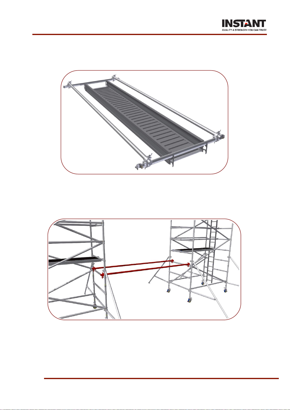
17. Place a loose horizontal brace in hooks at each end of a spandeck. Rest two spandeck handrails
across horizontal braces, running parallel to spandeck. Fix right angle couplers between each
handrail and brace at each end. Detach couplers from horizontal braces (couplers fixed to handrail
now have centres as spandeck).
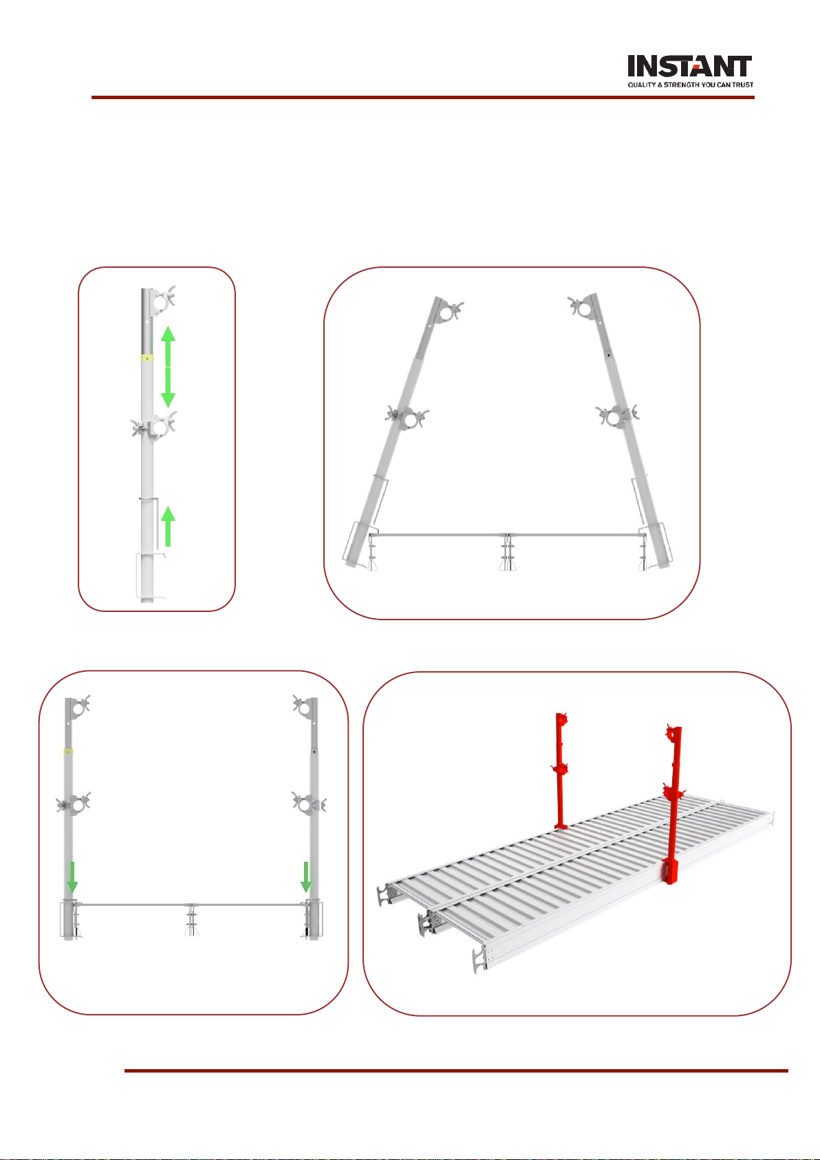
18. Temporally couple both towers together by fixing couplers mounted on handrail to horizontal tubes
of the tower frames. Adjust the position of the second tower as necessary to achieve the same tower
spacing as the couplers. Make necessary adjustments to ensure both towers are square to each
other and apply the brakes.
Page 20 of 38
SPAN 500 BRIDGED TOWER
19. Install the spandeck posts and handrail while the spandeck is on the ground. Adjust the Spandeck
guardrail posts to have centre distance of 450mm below top coupler. Slide the pin up the tube to
allow for installation.
20. Mount the required number of Spandeck guardrail posts to the side of the spandeck. Do the same
for the opposite side of Spandeck.
21. Slide the locking pin into the designated hole of the Spandeck, positively locking the post into
position.
22. Remove the spandeck handrails from the base and install them to the guardrail posts.
This manual suits for next models
1
Table of contents
Other Instant Upright Desktop manuals


