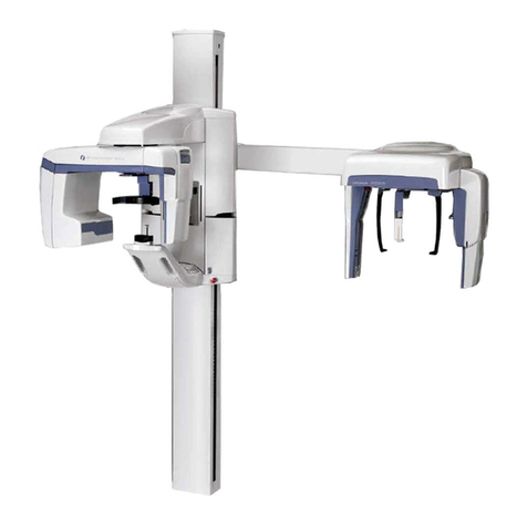
Instrumentarium Orthopantomograph OP200 User manual

Orthopantomograph® OP200
Orthoceph® OC200
Installation Manual
5139614-100 rev 4


Copyright Code: 5139614-100 rev 4 Date: 22 May 2008
Document code: D500409 rev 4
Copyright © 05/2008 by PaloDEx Group Oy.
All rights reserved.
Manufactured by Instrumentarium Dental
Nahkelantie 160 (P.O. Box 20)
FI-04300 Tuusula
FINLAND
Tel. +358 45 7882 2000
Fax. +358 9 851 4048
Orthopantomograph®and Orthoceph®are registered trademarks
of Instrumentarium Dental. U.S. patents 4,641,336; 5,016,264;
5,425,065, 5,444,754, 6,731,717 and 6,829,326. German patent
4,344,745. Finnish patents 112594 and 114383. Windows®is
trademark of Microsoft Corporation in the United States of
America and other countries. Pentium®is a registered trademark
of Intel Corporation. Iomega®Jaz®is a registered trademark of
Iomega Corp.
Documentation, trademark and the software are copyrighted
with all rights reserved. Under the copyright laws the
documentation may not be copied, photocopied, reproduced,
translated, or reduced to any electronic medium or machine
readable form in whole or part, without the prior written
permission of Instrumentarium Dental.
The original language of this manual is English.
Instrumentarium Dental reserves the right to make changes in
specification and features shown herein, or discontinue the
product described at any time without notice or obligation.
Contact your Instrumentarium Dental representative for the most
current information.
For service, contact your local distributor.


5139614-100 rev 4 Instrumentarium Dental i
Table of Contents
1 Introduction..................................................................................................................1
1.1 General .................................................................................................................1
1.2 Graphics symbols..................................................................................................3
1.3 Type and version...................................................................................................4
1.4 Radiation protection guidelines.............................................................................6
1.4.1 Protection by distance................................................................................6
1.4.2 Control from a protected environment........................................................7
1.5 Laser lights............................................................................................................8
1.6 Emergency Stop Switch........................................................................................9
1.7 Unit identification labels ......................................................................................10
1.8 Manufacturer’s liability.........................................................................................12
1.9 Disposal ..............................................................................................................12
2 Installation requirements and dimensions..............................................................13
2.1 Column options...................................................................................................13
2.2 Column mounting options ...................................................................................14
2.3 OP/OC200 recommended minimum installation dimensions
............................................................................................................................15
2.4 Unit orientation options .......................................................................................17
2.5 Site requirements and dimensions......................................................................18
2.5.1 Radiation Shielding..................................................................................18
2.5.2 Radiation Safety.......................................................................................18
2.5.3 Package dimensions................................................................................18
2.5.4 Door width................................................................................................18
2.5.5 Patient Access Area.................................................................................18
2.5.6 Location....................................................................................................18
2.5.7 Unit mounting...........................................................................................19
2.5.8 Floor.........................................................................................................19
2.5.9 Remote exposure button (optional)..........................................................19
2.5.10 Mains connection.....................................................................................19
2.5.11 Protective ground.....................................................................................20
2.6 Dark room and film storage.................................................................................20
2.6.1 Dark Room...............................................................................................20
2.6.2 Safelight...................................................................................................20
2.6.3 Processor.................................................................................................20
2.6.4 Film & Storage .........................................................................................20
2.7 Tools and hardware ............................................................................................21
3 Preparing for the installation....................................................................................23
3.1 Checking the shipment........................................................................................23
3.1.1 Checking the boxes..................................................................................23
3.2 Opening the boxes..............................................................................................23
3.2.1 Unpacking the column..............................................................................23
3.2.2 Unpacking the carriage............................................................................25
4 Hardware installation ................................................................................................27
4.1 Column installation..............................................................................................27
4.1.1 Wall mount bracket ..................................................................................27

ii Instrumentarium Dental 5139614-100 rev 4
4.1.2 Optional fork stand installation.................................................................30
4.1.3 Erecting the column .................................................................................32
4.2 Vertical carriage installation................................................................................33
4.2.1 Lifting and fastening the carriage.............................................................33
4.2.2 Adjusting and fastening the unit...............................................................37
4.2.3 Electrical connections ..............................................................................38
4.2.4 Rotation lock removal...............................................................................40
4.2.5 Carriage locking plate removal.................................................................42
4.3 Film Cephalostat installation (optional)...............................................................43
4.3.1 Preparing the unit for cephalostat installation..........................................43
4.3.2 Unpacking the cephalostat.......................................................................44
4.3.3 Cephalostat arm mounting.......................................................................44
4.3.4 Cephalostat electrical connections...........................................................47
4.3.5 Cephalostat head mechanical adjustments .............................................48
4.3.6 Cephalostat head mechanical adjustments .............................................49
4.4 Finalizing the hardware installation.....................................................................51
4.4.1 Mains voltage connection.........................................................................51
4.4.2 Changing the mains voltage from 230 V to 110 V....................................52
4.4.3 Removing counterweight transport security bolt......................................55
4.4.4 Control panel............................................................................................55
4.4.5 Remote exposure button (optional)..........................................................55
4.4.6 Installing the unit covers...........................................................................56
4.4.7 Loading the panoramic cassette..............................................................57
4.4.8 Panoramic cassette sensitivity control.....................................................57
4.4.9 Powering up the unit for the first time.......................................................58
5 Film unit adjustments and calibration.....................................................................59
5.1 General instructions............................................................................................59
5.2 STEP 1: Panoramic adjustments and calibrations..............................................60
5.2.1 Panoramic beam alignment check...........................................................60
5.2.2 Image layer check and alignment ............................................................65
5.2.3 Patient positioning laser lights check and alignment................................67
5.2.4 Tomographic layer check.........................................................................73
5.2.5 AEC calibration ........................................................................................76
5.3 STEP 2: Optional cephalostat adjustment and calibration..................................77
5.3.1 Cephalostat beam check and alignment..................................................77
5.3.2 Ear holder check and alignment...............................................................79
5.3.3 Soft tissue wedge alignment....................................................................81
6 Handing over the unit................................................................................................85
6.1 Panel functions....................................................................................................85
6.2 Quality checks.....................................................................................................86
6.2.1 Film contrast and density settings with QA image ...................................86
6.3 Accessories and disposables..............................................................................87
6.4 Application training..............................................................................................87
7 Appendix A, OP200 installation
check list ....................................................................................................................89
8 Appendix B, Unit orientation change.......................................................................91
8.1 Panoramic patient positioning orientation change ..............................................91

5139614-100 rev 4 Instrumentarium Dental iii
8.2 Cephalostat orientation change ..........................................................................95
9 Appendix C, Cephalostat upgrade.........................................................................103
9.1 Cephalostat upgrade kit content .......................................................................103
9.2 Unpacking instructions......................................................................................103
9.3 Counter weight..................................................................................................103
9.3.1 Adding trim weights................................................................................103
9.4 Collimator and tubehead cover.........................................................................106
9.5 Installation of the cephalostat............................................................................107
9.6 Alignments ........................................................................................................107
10 Appendix D, Re-packing instructions....................................................................109
10.1 Preparing the unit for re-packing.......................................................................109
10.1.1 Cephalostat head...................................................................................109
10.1.2 Carriage .................................................................................................110
10.2 Cephalostat package ........................................................................................112
10.3 Carriage package..............................................................................................113
10.4 Column package...............................................................................................115
11 Appendix E, CR kit installation...............................................................................117

iv Instrumentarium Dental 5139614-100 rev 4

1 Introduction
5139614-100 rev 4 Instrumentarium Dental 1
1 Introduction
1.1 General
Orthopantomograph®OP200 is a software controlled
diagnostic panoramic dental x-ray equipment for producing
high quality images of dentition and TM-joints. Orthoceph®
OC200 model is a more equipped x-ray panoramic unit
with cephalometric exposure option.
This manual covers the installation of panoramic unit,
cephalostat and Ortho Trans options. For information
about how to use OP200 please refer to the appropriate
manuals.
Following manuals are shipped with the OP200:
OP200 Installation & Adjustments Manual
OP200 User Manual & Technical Specifications
OP200 Ortho Trans User Manual (only if Ortho Trans
option purchased with the OP200 unit)
These manuals and future updates are available on
request from Instrumentarium Dental.
In order to maintain safe and correct operation of the
OP200 unit, read and follow carefully instructions provided
in this manual during the unit installation process.
Use only approved cables and plugs.
Mains connector types:
– NEMA 6-15P or similar Hospital grade (US/230 V)
– NEMA 5-20P or similar Hospital grade (US/110 V)
– HBL8215C or similar Hospital grade (JAPAN)
Power supply cord:
– For UL-countries: S or SO, AWG 14x3
– H05VV-F3G 10-16A 250V (CE)

1 Introduction
2 Instrumentarium Dental 5139614-100 rev 4
WARNING! SERVICING AND INSTALLING THIS UNIT
WITHOUT ADEQUATE EXPERTISE IS EXTREMELY
DANGEROUS. Instrumentarium Dental recommends that
all service operations are performed by Instrumentarium
Dental authorized service personnel!
WARNING! Prevent unauthorized access to unit during
the unit installation process. Some internal parts of the unit
contain dangerous voltage, which can be reached during
the installation, when the unit covers have been removed.
WARNING! The mains filter and connected cables are still
energized even when the unit is switched off (see wiring
diagram in chapter 4.4.1 Mains voltage connection). The
mains power cord must be unplugged from the wall socket
when the mirror plate is removed during the unit
installation.
WARNING! Some installation
procedures instructed in this
manual require X-radiation
exposures. Follow the local
regulations with radiation safety
issues.

1 Introduction
5139614-100 rev 4 Instrumentarium Dental 3
1.2 Graphics symbols
The following symbols are used in the OP200.
Radiographic control
Protective earth (ground)
Type B equipment
Dangerous voltage
On (Power)
Off (Power)
Attention, consult accompanying documents
If the unit has CE-marking it is CE-marked
according to the Medical Device Directive
93/42/EEC.
If the unit has UL-marking, it is UL-marked
according to UL60601-1 and CAN/CSA C22.2
No.601.1
This symbol indicates that the waste of electrical
and electronic equipment must not be disposed as
unsorted municipal waste and must be collected
separately. Please contact an authorized
representative of the manufacturer for information
concerning the decommissioning of your
equipment.

1 Introduction
4 Instrumentarium Dental 5139614-100 rev 4
1.3 Type and version
The type and version of the OP200 is defined in the unit
main label. It is located on the vertical carriage bottom
plate next to the power on/off switch or in the column label.
The unit is class I, type B and with IP-20 protection.
Fig 1.1. Location of main label and CE mark
Fig 1.2. Main label (230 V) Fig 1.2. Main label (110 V)

1 Introduction
5139614-100 rev 4 Instrumentarium Dental 5
The unit type numbers appear in the following form:
OP200-a-b-S.
For example, OP200-1-1 is:
(OP200) Orthopantomograph®OP200
(-1) with Toshiba D-051S tube
(-1) first version of OP200.
NOTE! In order to maintain safe and correct functioning of
OP200, only the approved accessories may be used.
TYPE AND VERSION
OP200 short form for Orthopantomograph®OP200
OC200 short form for Orthoceph®OC200
atype of the x-ray tube insert which is originally
utilized:
1 = Toshiba D-051S
bversion number:
1 = OP200 models starting from
s/n 100 000
Sindication of a "Special" version, marked only in
products which have a non-standard modification

1 Introduction
6 Instrumentarium Dental 5139614-100 rev 4
1.4 Radiation protection guidelines
X-ray equipment may cause injury if used improperly. The
instructions contained in this manual must be read and
followed when operating the Orthopantomograph®OP200.
All government and local regulations pertaining to radiation
safety must be observed.
NOTE! For USA: Many provisions of these regulations are
based on recommendations of the National Council on
Radiation Protection and Measurements.
Recommendations for dental x-ray protection are
published in NCRP Report #35 available from NCRP
Publications, 7910 Woodmont Avenue, Suite 1016,
Bethesda, MD 20814.
Personal radiation monitoring and protective devices are
available and recommended for staff members. It is also
recommended to provide the patient with a protective
apron. Consult the physician before taking images of
pregnant patients.
OP200 with radiation protection in accordance with
IEC601-1-3:1994.
CAUTION! Use of controls or adjustments or performance
of procedures other than those specified herein may result
in hazardous radiation exposure.
1.4.1 Protection by distance
In all examinations the user of the x-ray equipment should
wear protective clothing. The operator does not need to be
close to the patient during normal use. The protection
against stray radiation can be achieved by using the hand
switch not less than 2 m (7 ft.) from the focal spot and the
x-ray beam. Operator should maintain visible contact with
the patient and technique factors. This allows immediate
termination of radiation by the release of the exposure
button in the event of a malfunction or disturbance.
Caution information on control panel:
CAUTION X-RAYS
ATTENTION
RAYONS X
WARNING:
This x-ray unit may be dangerous to patient and operator
unless safe exposure factors, operating instructions and
maintenance schedules are observed.

1 Introduction
5139614-100 rev 4 Instrumentarium Dental 7
1.4.2 Control from a protected environment
The operator does not need to be close to the patient
during normal use. Control panel hand switch or optional
remote hand switch can be used from environment
protected from the x-ray beam. The fully extended spiral
cable length of the control panel hand switch is approx. 4 m
(13 ft). The cable length of the remote hand switch (part no.
69961) is approximately 10 m (32 ft).

1 Introduction
8 Instrumentarium Dental 5139614-100 rev 4
1.5 Laser lights
1. FH-light
2. Mid-Sagittal light
3. Layer light
4. Tomographic laser light (Ortho Trans option)
Fig 1.3. Laser light (CLASS 1 LASER PRODUCT). Max output 100µW.

1 Introduction
5139614-100 rev 4 Instrumentarium Dental 9
1.6 Emergency Stop Switch
An emergency stop switch is provided on the right side of
the unit carriage and on the bottom of the cephalostat head
(option) so, that the patient can reach either of them.
If the emergency stop switch is pressed during an
exposure, the exposure is terminated immediately and the
x-ray unit is completely stopped. The interrupted exposure
cannot be continued later, but has to be retaken from the
beginning.
NOTE! Before switching the unit on, ensure that the
emergency stop switches are released.

1 Introduction
10 Instrumentarium Dental 5139614-100 rev 4
1.7 Unit identification labels
1. Cephalostat cassette head label
2. Main Label
3. Unit serial number and type label
4. Tomographic laser light label

1 Introduction
5139614-100 rev 4 Instrumentarium Dental 11
NOTE! Some labels listed above are related to some
options and may not be included in all countries.
5. Panoramic cassette head label
6. Mid-Sagittal and FH-light laser
label
7. Laser light warning label
8. Image layer laser light label
9. Collimator type label
10. X-ray generator and tubehead
label

1 Introduction
12 Instrumentarium Dental 5139614-100 rev 4
1.8 Manufacturer’s liability
As a manufacturer we can only assume liability of safe and
reliable operation of this unit when
Installation is performed according to the OP200
Installation & Adjustments Manual
The unit is used according to the OP200 User Manual
Ortho Trans option is used according to OP200 Ortho
Trans User Manual
Maintenance and repairs are performed by a qualified
Orthopantomograph®OP200 Dealer
Original or authorized spare parts are used
In order to quarantee maximal image quality for entire life
time of this high performance imaging system, we suggest
that the quality assurance procedure *) and test object
designed for image quality assurance purposes are used
(code 68795). Also we recommend qualified serviceman to
check the unit to be in its original condition regarding
electrical, radiation and mechanical safety according to our
maintenance program described in more details in
maintenance manual (code 61049) every year or after
2000 images. For more information please contact your
local dealer.
*) According EN61223-3-4 and DIN 6868-151
If service on the unit is performed, a work order describing
the type and extent of repair must be provided by the
service technician. This must contain information of
changes of nominal data or work range performed. The
work order must furthermore indicate the date of repair, the
name of the company concerned and a valid signature.
The user should keep this work order for future references.
1.9 Disposal
Follow the local regulations on disposal of waste parts.
OP200 has at least the following parts that should be
regarded as non-environmental friendly waste products:
– X-ray source assembly
– All electronic circuits
– Column counter weight (Pb)
Other manuals for Orthopantomograph OP200
1
This manual suits for next models
1
Table of contents
Other Instrumentarium Dental Equipment manuals

Instrumentarium
Instrumentarium Orthopantomograph OP100 D Guide

Instrumentarium
Instrumentarium Orthoceph OC100 D Quick start guide

Instrumentarium
Instrumentarium Orthopantomograph OP200 D User manual

Instrumentarium
Instrumentarium Orthoceph OC200 D User manual

Instrumentarium
Instrumentarium Orthopantomograph OP200 D User manual

Instrumentarium
Instrumentarium Express User manual


