Instrumentation GDD GRx8-32 User manual

IP RECEIVER
Model GRx8-32
Instruction Manual
860 boul. de la Chaudière, suite 200
Québec (QC), Canada, G1X 4B7
Tel.: +1 (418) 877-4249
Fax: +1 (418) 877-4054
E-Mail: gdd@gdd.ca
Web site: www.gdd.ca

Instrumentation GDD Inc. 2017-12-14 Page 2
Visit our web site at:
WWW.GDD.CA
To:
•Disco er GDD’s new products.
•Download the latest ersion of the Instruction Manual.
•Comment on or ask questions about products.

Instrumentation GDD Inc. 2017-12-14 Page 3
1. Introduction .................................................................................................................. 5
2. Receiver Accessories ......................................................................................................
3. Receiver Components .................................................................................................... 8
4. Power ......................................................................................................................... 11
5. Quick Start Guide ........................................................................................................ 14
. RS232/Bluetooth Communication ................................................................................ 22
7. Cold weather and harsh environments tips .................................................................. 23
8. Tools Menu ................................................................................................................. 24
8.1 Config option .......................................................................................................... 26
8.1.1 Setup .................................................................................................................. 26
8.1.2 Position ............................................................................................................... 28
8.1.3 Windows ............................................................................................................. 30
8.1.4 Synchroni ation ................................................................................................... 35
8.2 Special option ......................................................................................................... 38
8.2.1 Reinit .................................................................................................................. 38
8.2.2 Simulation ........................................................................................................... 39
8.2.3 Signal Processing Options .................................................................................... 43
8.2.4 Battery type ........................................................................................................ 44
8.2.5 Open Port ............................................................................................................ 46
8.3 Show option ............................................................................................................ 47
8.3.1 Hotkeys ............................................................................................................... 47
8.3.2 Pseudosection ..................................................................................................... 48
8.3.3 Signal .................................................................................................................. 50
8.3.3.1 Tools menu ........................................................................................................... 52
8.3.3.1.1 Auto Correction.............................................................................................. 52
8.3.3.1.2 Restore ........................................................................................................... 52
8.3.3.1.3 PAUSE/GO ...................................................................................................... 53
8.3.4 Contact and Noise ............................................................................................... 53
8.3.5 Vp and Cycle ........................................................................................................ 54
8.3.6 Show M and errM ................................................................................................ 55
8.3.7 Decay Curve ........................................................................................................ 56
8.3.8 Show Windows .................................................................................................... 57
8.3.9 Show Sp .............................................................................................................. 58
8.4 Raw Data Option ..................................................................................................... 59
8.4.1 Check GPS ........................................................................................................... 59
8.4.2 Start Recording (raw data) ................................................................................... 62
8.5 Memory Option ...................................................................................................... 65
8.5.1 Display Reading ................................................................................................... 65
8.5.2 History ................................................................................................................ 66
8.5.3 Back Mem ........................................................................................................... 67
TABLE OF CONTENTS

Instrumentation GDD Inc. 2017-12-14 Page 4
8.5.4 Clear Mem ........................................................................................................... 68
8.5.5 Save File .............................................................................................................. 69
8.6 About Option .......................................................................................................... 72
9. Transferring data ........................................................................................................ 73
9.1 ActiveSync .............................................................................................................. 73
9.1.1 Installation and settings ...................................................................................... 73
9.1.2 Establishing connection with a desktop PC ........................................................... 74
9.1.3 Transferring file(s) from the Allegro
2
to a desktop PC ........................................... 75
9.2 Windows Mobile Device Center ............................................................................... 77
9.2.1 Installation and settings ...................................................................................... 77
9.2.2 Establishing connection with a desktop PC ........................................................... 78
9.2.3 Transferring file(s) from the Allegro
2
to a desktop PC ........................................... 79
9.3 USB connection ....................................................................................................... 81
10. Bluetooth configuration .............................................................................................. 83
11. GDD Rx software update ............................................................................................. 87
12. Troubleshooting .......................................................................................................... 89
13. Specifications .............................................................................................................. 95
13.1 General specifications ............................................................................................. 95
13.2 Technical specifications ........................................................................................... 95
14. Technical help ............................................................................................................. 97
Annex 1 – Geometrical parameters ...................................................................................... 98
Annex 2 – 3D Survey .......................................................................................................... 104
Annex 3 – Field survey setup .............................................................................................. 11
Annex 4 – Example Dump File ............................................................................................ 138

Instrumentation GDD Inc. 2017-12-14 Page 5
1. Introduction
The highly sensiti e GDD IP Recei er models GRx8-32 is a compact unit designed for high
producti ity resisti ity and time-domain induced polarization (IP) sur eys in mineral exploration,
groundwater exploration, geotechnical in estigations and other related fields. It features high
capabilities allowing it to work in any field conditions. It can be configured for multi-pole or multi-
dipole reception. The recei er uses a rugged field PC to process data acquisition and the software
can easily be updated ia internet.
Characteristics:
•Reception poles/dipoles: 8 poles/dipoles, expandable to 32, for dipole-dipole, pole-dipole
or pole-pole arrays.
•Programmable windows: The GRx8-32 offers twenty fully programmable windows for
higher flexibility in defining the IP decay cur e.
•User modes available: Arithmetic, logarithmic, semi-logarithmic, Cole-Cole and user
defined.
•IP display: Chargeability alues, Apparent Resisti ity, IP decay cur es and pseudosections
can be displayed in real time thanks to the TFT VGA screen. Before data acquisition, the
GRx8-32 can be used as a one channel graphic display for monitoring the noise le el and
checking the primary oltage wa eform through a continuous display process.
•Internal memory: Capacity to store up to 64 000 readings for 8 poles/dipoles, memory
expandable to 512 000 readings on the PDA model. Each reading includes the full set of
parameters characterizing measurements. Data is stored on flash type memory that does
not require any lithium battery for safeguard purposes.
•Full wave data with IP Post-Processing software: The GRx8-32 records and sa es the full
wa e data (*.mem file). This raw data can be imported, isualized and processed using
GDD's IP Post-Processing software.

Instrumentation GDD Inc. 2017-12-14 Page 6
2. Receiver Accessories
A 1x IP Recei er, model GRx8-32
B 1x UART programming adapter (Boot Loader)
C 1x Allegro
2
field computer with a 10.6Ah rechargeable Li-Ion battery and an
adjustable hand strap
D 1x Allegro
2
capaciti e stylus with tether
E 1x Allegro
2
Holster case
F 1x Allegro
2
wall charger with international plug kit
G 1x IP Recei er charger (power supply) with international plug kit
H Blue cables with black banana connectors or red banana connectors
I 1x Standard serial communication cable
J 2x Rugged serial communication cables (Amphenol connector)
K 2x Micro USB Communication Cables
L 1x External GPS antenna (SMA connector)
M 1x GDD-BP02 External battery pack (optional for 8 to 16 channels receivers)
N 1x Input signals connector (41 positions)
O 1x Allegro
2
Quick Start Guide
P 1x GDD Instruction manual
Q 1x Screwdri er
R 1x IP Recei er documentation CD / USB stick
Not shown on the illustration:
1x Blue carrying case
1x GDD-RTE01 communication box with USB cable (optional accessory)
1x GDD IP Post-Processing Software User Guide
Optional accessories:
GDD-BP02 External battery pack (for 8 10 to 16 channels receivers)
GDD-RTE01 communication box with USB cable

Instrumentation GDD Inc. 2017-12-14 Page 7
The items supplied with the de ice and a ailable accessories may differ from the picture.
A
C
D
F
G
H
I
J
K
L
M
(optional)
N
O
F
R
B
C
E
P
Q

Instrumentation GDD Inc. 2017-12-14 Page 8
3. Receiver Components
The GRx8-32 components are described in this section.
A - RS-232 connector - 9 pin serial communication port
This connector is used to connect the RS-232 cable between the Allegro
2
and the GRx8-32.
B - CABLE/WIRELESS switch
This switch is used to select CABLE (RS-232) or WIRELESS (Bluetooth) communication with
the PDA. The red light indicates that the switch is in the WIRELESS position.
C - HARDWARE connector - 15 pin programming port
This connector is used to update the CPU and PLD software.
D - GPS Connector
This connector is used to connect an external GPS antenna (SMA).
A
B
C
D
E
F
G
H
I
J

Instrumentation GDD Inc. 2017-12-14 Page 9
E - ON/OFF/SELF-TEST switch
This switch is used to turn the GRx8-32 ON or to perform a self-test. The red light indicates
that the GRx8-32 is ON or in the SELF-TEST position.
F - INTERNAL/EXTERNAL BATTERY switch
This switch is used to select the internal batteries or the external battery pack, pro ided by
GDD.
G - CHARGER connector
This connector is used to charge the recei er batteries. The Internal Battery / External
Battery (F) switch must be on Internal battery.
H - R1 to R4 terminals
In pole configuration, the reference terminals (R1 to R4) are the infinite electrodes. In dipole
configuration, the reference terminal is the first electrode in differential with the second
electrode.
I - NUMBERED terminals
These terminals are referenced to the Ref terminal (Ref is infinity in pole configuration). In
dipole configuration, the numbered terminals are differential terminals.
J - SELF-TEST terminal
This terminal is used to perform a self-test.

Instrumentation GDD Inc. 2017-12-14 Page 10
K - RS-232 external Connector
This connector is used to connect the rugged serial communication cable (Amphenol
connector), which allows communication between the Allegro
2
and the GRx8-32 recei er.
L - Input signal connector
This connector is used to connect the wires coming from the
electrodes to the recei er channels to keep the Pelican case closed
while taking the readings. A cable mount connector (41 pos.) is
included with the recei er accessories and can be used with the
instrument.
M - External battery connector
This connector is used to connect the external battery pack. The Internal/External battery
switch (F) must be on External battery position.
CH30
CH23
SPARE1
SPARE2
CH22
SPARE3
SPARE4
SPARE5
CH29
CH21
CH28
CH20
J3
PT02E-20-41S
A
B
C
D
E
F
G
H
J
K
L
M
N
P
R
S
T
U
V
W
X
Y
Z
a
b
c
d
e
f
g
h
i
j
k
m
n
p
q
r
s
t
CH27
CH19
CH26
CH18
CH5
CH4
CH13
CH11
CH16
CH31
CH25
REF3
CH17
CH3
CH6
CH12
CH14
CH7
CH15
REF4
CH32
REF1
CH8
REF2
CH9
CH10
CH1
CH2
CH24
K
L
M

Instrumentation GDD Inc. 2017-12-14 Page 11
GDD’s IP Recei er, model GRx8-32, is powered by internal rechargeable Nickel Cadmium /
Lithium-ion batteries or an external rechargeable Nickel Cadmium / Lithium-ion battery pack.
Refer to your recei er’s charger to find out which type of batteries your recei er has.
Ni-CD batteries Li-Ion batteries
The power le el of the Rx internal batteries is indicated on the main screen of the Allegro
2
of the
GDD Rx software.
Here are a few tips for using and storing your lithium-ion powered recei er:
Usage
•Using a different battery power supply than the one supplied by GDD could damage the
batteries and the receiver.
•The connector located on the back of the receiver is used to connect the External
Battery Pack supplied by GDD. Connecting other external batteries using this connector
could damage the batteries and the receiver.
4. Power

Instrumentation GDD Inc. 2017-12-14 Page 12
•Do not replace the receiver's internal batteries without authori ation and advice from
GDD’s technicians.
•The total operating time of the recei er depends on en ironmental conditions. Using the
recei er in ery cold weather (-20
0
C to –40
0
C) will lower the operating time.
•The recei er will turn itself off when the batteries reach a critical le el.
•To extend battery life, a oid frequent full discharge and charge more often between each
use.
•A LED under the Internal battery switch on the recei er is red when the batteries are
charging. It turns off once the batteries are fully charged.
Storage
•To a oid permanent capacity loss, store the recei er and the external battery pack at 40%
charge.
•Store the recei er and the external battery pack in a cool, dry place.
•Place the “Internal battery / External battery” switch on “External battery” position to
minimize self-discharge of the batteries.
•If stored for se eral months, check the battery charge le el e ery six months and recharge
them to 50% if they are below 30% charge.
Ne er store fully charged or completely discharged Lithium-Ion batteries for an extended
period of time.

Instrumentation GDD Inc. 2017-12-14 Page 13
Here are a few tips for using and storing your Ni-CD powered recei er:
Usage
•Using a different battery power supply than the one supplied by GDD could damage the
batteries and the receiver.
•The connector located on the back of the receiver is used to connect the External
Battery Pack supplied by GDD. Connecting other external batteries using this connector
could damage the batteries and the receiver. If the receiver does not have the external
battery pack connector, use the Charger connector to connect the External battery pack.
•Do not replace the receiver internal batteries without the authori ation and advice from
GDD’s technicians.
•The total operating time of the recei er will depend on the en ironmental conditions.
Using the recei er in ery cold weather (-20
0
C to –40
0
C) will lower the operating time.
•The recei er will turn itself off when the batteries reach a critical le el.
•To extend battery life, a oid frequent full discharge and charge more often between uses.
Storage
•To a oid permanent capacity loss, store the recei er and the external battery pack at 40%
charge.
•Store the recei er and the external battery pack in a cool and dry place.
•Place the “Internal battery / External battery” switch on “External battery” position to
minimize self-discharge of the batteries.
•If stored for se eral months, check the batteries charge le el e ery six months and
recharge them up to 50% if they are below 30% charge.

Instrumentation GDD Inc. 2017-12-14 Page 14
5. Quick Start Guide
1. Connect electrodes into terminals.
2. Turn ON the IP recei er using the ON/OFF switch on the GRx8-32 panel.
3. Select the communication mode using the CABLE/WIRELESS switch on the GRx8-32 panel.
In CABLE mode, the red light will turn ON only when the GRx8-32 software is acti e.
4. Connect the rugged serial communication cable (Amphenol connector) between the
Allegro
2
(COM1) and the GRx8-32 RS-232 external connector (CABLE communication only).
5. Turn ON the Allegro
2
with the ON/OFF button.
6. Click GDD RX.

Instrumentation GDD Inc. 2017-12-14 Page 15
7. Select the communication mode: RS-232 (CABLE) or BLUETOOTH (WIRELESS).
8. The following screen appears.
9. Click START or press Enter keystroke to begin the acquisition procedure.
Note: If you want to start the process by using the same settings than those of the
pre ious acquisition procedure, press F5 button. You ha e to start the first acquisition
normally before being able to use F5 for the next acquisitions. Using F5 will skip all
configuration and contact resistance windows. If F1 to F5 keystrokes do not work on your
Allegro
2
, see Section 12 – Troubleshooting.
Line number and direction
Transmitter and recei er position
Trigger channel count and oltage
Memory number and Rx battery le el
Ok button: Exit GDD Rx Software
START/STOP button: Start or Stop readings
TOOLS button: Rx option menu
Number of channels

Instrumentation GDD Inc. 2017-12-14 Page 16
10. The following screen appears. Click OK to continue.
11. Enter the project, line, station, mo e displacement, etc. for Tx and Rx. Click OK to
continue.
12. Verify if the positions are correct and click OK or press Enter keystroke to continue.
Displacement
enabled
Go to
pre ious
station
(or press F1
keystroke)
Go to
next
station (or
press F2
keystroke)
Go to
pre ious line
(or press F3
keystroke)
Go to
next
line (or press
F4
keystroke)

Instrumentation GDD Inc. 2017-12-14 Page 17
13. The Contact and Noise graph appears. If the alues displayed are normal, click OK or press
ESC keystroke to close the window.
14. Click NEXT or press Enter keystroke to continue.
*Note: If all stations show an INFINITE contact, the reference electrode might be
disconnected.
15. Enter the transmitter current and click CONFIRM or press Enter keystroke to start the
readings.

Instrumentation GDD Inc. 2017-12-14 Page 18
16. The following screens appear.
If using the optional GDD-RTE01 communication box (refer to section 8.2.5) to collect li e
information broadcasted by the GDD Tx4 IP transmitter, the Tx current ''I'' and power ''P'' can
be displayed alternati ely in the Rx main screen under the TOOLS and STOP/START buttons. To
switch from one information to the other, use the following shortcut Key: “V” or click on the
text label directly on the screen.
If no transmitter information can be recei ed at the GRx8-32, the following symbol will be
displayed instead of I and P: N/A.
17. Click STOP or wait until the end of the acquisition to stop the readings and sa e the data.

Instrumentation GDD Inc. 2017-12-14 Page 19
18. Click YES to confirm the operation.
19. Click YES to sa e readings into the memory.
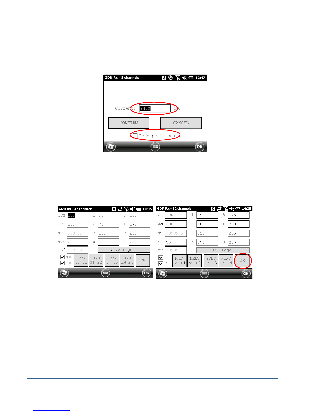
20. Re-enter the transmitter’s output current alue if it has changed and click CONFIRM to
sa e the current alue.
If using the optional GDD-RTE01 communication box (refer to section 8.2.5) to collect li e
information broadcasted by the GDD Tx4 IP transmitter, this menu will show additional Tx
current options to choose as the final “I” alue. These are the first “I” transmitted, the
a erage “AI” (with information regarding Standard De iation “SI” and a erage time
between each Tx alues broadcasted “AT”) and the last “I” transmitted. Click on one of the
corresponding button.
Instrumentation GDD Inc. 2017-12-14 Page 20
Check the REDO POSITIONS option to change the transmitter or recei er position.
Note: This option alters the reading that was just completed in order to correct or revise
the coordinates before saving the reading to the file. It should not be used to pre-set the
next reading.
If the REDO POSITIONS option is checked, enter the transmitter and recei er position and
click OK or press Enter keystroke.
*Each position can be changed indi idually or mo ed by clicking Next or Pre (or by using
F1 to F4 keystrokes).
NOTE: Once your acquisition is completed, use Left and Right arrow buttons on the keypad of
the Allegro
2
to compare your current data with that of your previous acquisitions. Use the Up
and Down arrows to see all the channels. By clicking on Start, the program will automatically
come back to the last acquisition and will start a new acquisition procedure.
Table of contents
Other Instrumentation GDD Receiver manuals

Popular Receiver manuals by other brands


SiKom
SiKom ECO Dimplex Receiver quick start guide

Scolmore
Scolmore ClickSmart RFJA-12b/230V Instruction leaflet

Niles
Niles ZR-6 installation guide

Audio Authority
Audio Authority Cat 5 Wall Plate & Enclosed Audio/Video Receivers Comparison... Specifications

Yamaha
Yamaha R-V902 owner's manual

Xantech
Xantech MICRO LINK 490-30 install guide